Page 1 of 20

CL-1
CLUTCH
C TRANSMISSION/TRANSAXLE
CONTENTS
D
E
F
G
H
I
J
K
L
M
SECTION CL
A
B
CL
Revision: 2006 November2007 350Z
CLUTCH
PRECAUTIONS .......................................................... 2
Precautions for Battery Service ................................ 2
Service Notice or Precautions .................................. 2
PREPARATION ........................................................... 3
Special Service Tools ............................................... 3
Commercial Service Tools ........................................ 3
NOISE, VIBRATION AND HARSHNESS (NVH)
TROUBLESHOOTING ................................................ 4
NVH Troubleshooting Chart ..................................... 4
CLUTCH PEDAL ........................................................ 5
On-Vehicle Inspection and Adjustment .................... 5
Removal and Installation .......................................... 6
COMPONENTS .................................................... 6
REMOVAL ............................................................. 6
INSPECTION AFTER REMOVAL ......................... 6
INSTALLATION ..................................................... 6
CLUTCH FLUID .......................................................... 7
Bleeding ................................................................... 7
CLUTCH MASTER CYLINDER .................................. 8
Components ............................................................. 8
Removal and Installation .......................................... 8
REMOVAL ............................................................. 8INSTALLATION ..................................................... 9
Disassembly and Assembly ...................................... 9
DISASSEMBLY ..................................................... 9
INSPECTION AFTER DISASSEMBLY .................. 9
ASSEMBLY ......................................................... 10
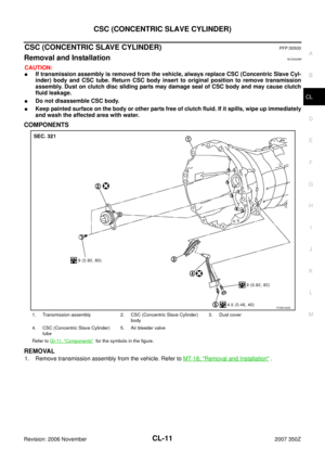
CSC (CONCENTRIC SLAVE CYLINDER) ................ 11
Removal and Installation ........................................ 11
COMPONENTS ................................................... 11
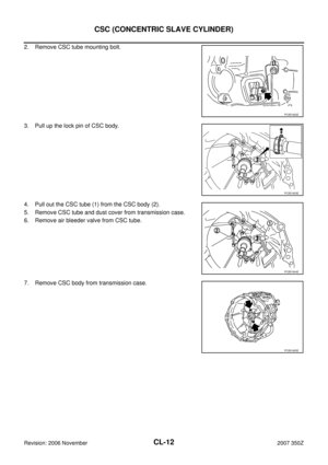
REMOVAL ........................................................... 11
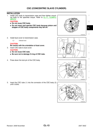
INSTALLATION ................................................... 13
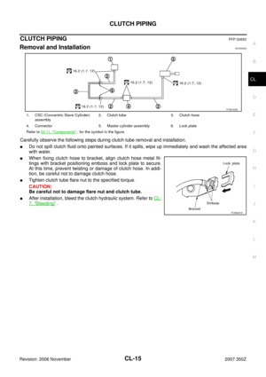
CLUTCH PIPING ....................................................... 15
Removal and Installation ........................................ 15
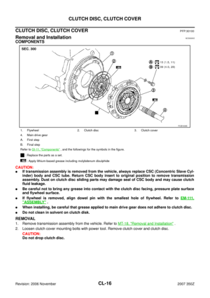
CLUTCH DISC, CLUTCH COVER ............................ 16
Removal and Installation ........................................ 16
COMPONENTS ................................................... 16
REMOVAL ........................................................... 16
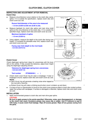
INSPECTION AND ADJUSTMENT AFTER
REMOVAL ........................................................... 17
INSTALLATION ................................................... 17
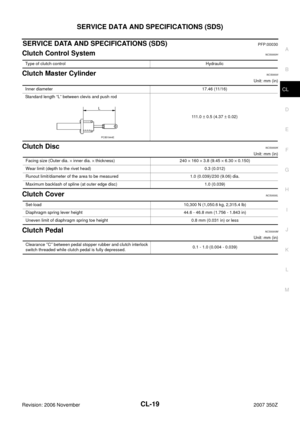
SERVICE DATA AND SPECIFICATIONS (SDS) ...... 19
Clutch Control System ............................................ 19
Clutch Master Cylinder ........................................... 19
Clutch Disc ............................................................. 19
Clutch Cover ........................................................... 19
Clutch Pedal ........................................................... 19
Page 2 of 20

CL-2
PRECAUTIONS
Revision: 2006 November2007 350Z
PRECAUTIONSPFP:00001
Precautions for Battery ServiceNCS00001
Before disconnecting the battery, lower both the driver and passenger windows. This will prevent any interfer-
ence between the window edge and the vehicle when the door is opened/closed. During normal operation, the
window slightly raises and lowers automatically to prevent any window to vehicle interference. The automatic
window function will not work with the battery disconnected.
Service Notice or PrecautionsNCS00002
�Recommended clutch fluid is brake fluid “DOT 3”. Refer to MA-11, "RECOMMENDED FLUIDS AND
LUBRICANTS" .
�Never reuse drained clutch fluid.
�Be careful not to splash clutch fluid on painted areas.
�When removing clutch tube, use a flare nut wrench.
�When installing clutch tube, use a flare nut torque wrench.
�Use new clutch fluid to clean or wash all parts of master cylinder.
�Never use mineral oils such as gasoline or kerosene. It will ruin
the rubber parts of the hydraulic system.
�If transmission assembly is removed from the vehicle, always
replace CSC (Concentric Slave Cylinder) body and CSC tube.
Return CSC body insert to original position to remove transmis-
sion assembly. Dust on clutch disc sliding parts may damage
seal of CSC body and may cause clutch fluid leakage.
�Do not disassemble CSC body.
WARNING:
After cleaning clutch disc, wipe it with a dust collector. Do not use compressed air.SBR686C
Page 3 of 20
PREPARATION
CL-3
D
E
F
G
H
I
J
K
L
MA
B
CL
Revision: 2006 November2007 350Z
PREPARATIONPFP:00002
Special Service ToolsNCS00003
The actual shapes of Kent-Moore tools may differ from those of special service tools illustrated here.
Commercial Service ToolsNCS00004
Tool number
(Kent-Moore No.)
Tool nameDescription
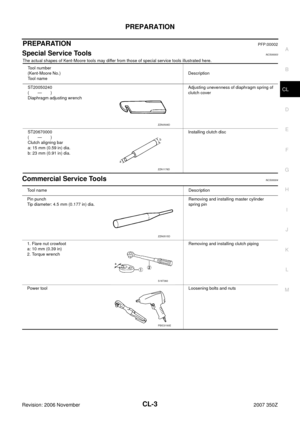
ST20050240
(—)
Diaphragm adjusting wrenchAdjusting unevenness of diaphragm spring of
clutch cover
ST20670000
(—)
Clutch aligning bar
a: 15 mm (0.59 in) dia.
b: 23 mm (0.91 in) dia.Installing clutch disc
ZZA0508D
ZZA1178D
Tool nameDescription
Pin punch
Tip diameter: 4.5 mm (0.177 in) dia.Removing and installing master cylinder
spring pin
1. Flare nut crowfoot
a: 10 mm (0.39 in)
2. Torque wrenchRemoving and installing clutch piping
Power toolLoosening bolts and nuts
ZZA0515D
S-NT360
PBIC0190E
Page 4 of 20
 TROUBLESHOOTING
Revision: 2006 November2007 350Z
NOISE, VIBRATION AND HARSHNESS (NVH) TROUBLESHOOTINGPFP:00003
NVH Troubleshooting ChartNCS00005
Use the chart")
CL-4
NOISE, VIBRATION AND HARSHNESS (NVH) TROUBLESHOOTING
Revision: 2006 November2007 350Z
NOISE, VIBRATION AND HARSHNESS (NVH) TROUBLESHOOTINGPFP:00003
NVH Troubleshooting ChartNCS00005
Use the chart below to help you find the cause of the symptom. The numbers indicate the order of the inspec-
tion. If necessary, repair or replace these parts.
Reference pageCL-5CL-7CL-9CL-11EM-101CL-16EM-134
SUSPECTED PARTS (Possible cause)
CLUTCH PEDAL (Free play out of adjustment)
CLUTCH LINE (Air in line)
MASTER CYLINDER PISTON CUP (Damaged)
CSC (Concentric Slave Cylinder) (Worn, dirty or damaged)
ENGINE MOUNTING (Loose)
CLUTCH DISC (Out of true)
CLUTCH DISC (Runout is excessive)
CLUTCH DISC (Lining broken)
CLUTCH DISC (Dirty or burned)
CLUTCH DISC (Oily)
CLUTCH DISC (Worn out)
CLUTCH DISC (Hardened)
CLUTCH DISC (Lack of spline grease)
DIAPHRAGM SPRING (Damaged)
DIAPHRAGM SPRING (Out of tip alignment)
PRESSURE PLATE (Distortion)
FLYWHEEL (Distortion)
SymptomClutch grabs/chatters 1 2 2 2 2 2
Clutch pedal spongy 1 2 2
Clutch noisy 1
Clutch slips 1 2 2 3 4 5
Clutch does not disengage 1 2 3 4 5 5 5 5 5 5 6 6 7
Page 5 of 20

CLUTCH PEDAL
CL-5
D
E
F
G
H
I
J
K
L
MA
B
CL
Revision: 2006 November2007 350Z
CLUTCH PEDALPFP:46540
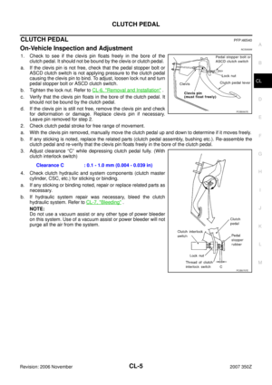
On-Vehicle Inspection and AdjustmentNCS00006
1. Check to see if the clevis pin floats freely in the bore of the
clutch pedal. It should not be bound by the clevis or clutch pedal.
a. If the clevis pin is not free, check that the pedal stopper bolt or
ASCD clutch switch is not applying pressure to the clutch pedal
causing the clevis pin to bind. To adjust, loosen lock nut and turn
pedal stopper bolt or ASCD clutch switch.
b. Tighten the lock nut. Refer to CL-6, "
Removal and Installation" .
c. Verify that the clevis pin floats in the bore of the clutch pedal. It
should not be bound by the clutch pedal.
d. If the clevis pin is still not free, remove the clevis pin and check
for deformation or damage. Replace clevis pin if necessary.
Leave pin removed for step 2.
2. Check clutch pedal stroke for free range of movement.
a. With the clevis pin removed, manually move the clutch pedal up and down to determine if it moves freely.
b. If any sticking is noted, replace the related parts (clutch pedal assembly, bushing etc.). Re-assemble the
clutch pedal and re-verify that the clevis pin floats freely in the bore of the clutch pedal.
3. Adjust clearance “C” while depressing clutch pedal fully. (With
clutch interlock switch)
4. Check clutch hydraulic and system components (clutch master
cylinder, CSC, etc.) for sticking or binding.
a. If any sticking or binding noted, repair or replace related parts as
necessary.
b. If hydraulic system repair was necessary, bleed the clutch
hydraulic system. Refer to CL-7, "
Bleeding" .
NOTE:
Do not use a vacuum assist or any other type of power bleeder
on this system. Use of a vacuum assist or power bleeder will not
purge all the air from the system.Clearance C : 0.1 - 1.0 mm (0.004 - 0.039 in)
PCIB0907E
PCIB0757E
Page 6 of 20
\" or EI-37,")
CL-6
CLUTCH PEDAL
Revision: 2006 November2007 350Z
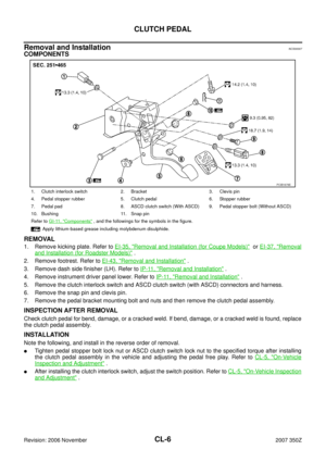
Removal and InstallationNCS00007
COMPONENTS
REMOVAL
1. Remove kicking plate. Refer to EI-35, "Removal and Installation (for Coupe Models)" or EI-37, "Removal
and Installation (for Roadster Models)" .
2. Remove footrest. Refer to EI-43, "
Removal and Installation" .
3. Remove dash side finisher (LH). Refer to IP-11, "
Removal and Installation" .
4. Remove instrument driver panel lower. Refer to IP-11, "
Removal and Installation" .
5. Remove the clutch interlock switch and ASCD clutch switch (with ASCD) connectors and harness.
6. Remove the snap pin and clevis pin.
7. Remove the pedal bracket mounting bolt and nuts and then remove the clutch pedal assembly.
INSPECTION AFTER REMOVAL
Check clutch pedal for bend, damage, or a cracked weld. If bend, damage, or a cracked weld is found, replace
the clutch pedal assembly.
INSTALLATION
Note the following, and install in the reverse order of removal.
�Tighten pedal stopper bolt lock nut or ASCD clutch switch lock nut to the specified torque after installing
the clutch pedal assembly in the vehicle and adjusting the pedal free play. Refer to CL-5, "
On-Vehicle
Inspection and Adjustment" .
�After installing the clutch interlock switch, adjust the switch position. Refer to CL-5, "On-Vehicle Inspection
and Adjustment" .
1. Clutch interlock switch 2. Bracket 3. Clevis pin
4. Pedal stopper rubber 5. Clutch pedal 6. Stopper rubber
7. Pedal pad 8. ASCD clutch switch (With ASCD) 9. Pedal stopper bolt (Without ASCD)
10. Bushing 11. Snap pin
Refer to GI-11, "
Components" , and the followings for the symbols in the figure.
: Apply lithium-based grease including molybdenum disulphide.
PCIB1678E
Page 7 of 20

CLUTCH FLUID
CL-7
D
E
F
G
H
I
J
K
L
MA
B
CL
Revision: 2006 November2007 350Z
CLUTCH FLUIDPFP:00017
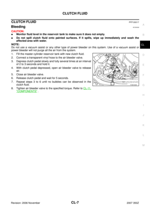
BleedingNCS00008
CAUTION:
�Monitor fluid level in the reservoir tank to make sure it does not empty.
�Do not spill clutch fluid onto painted surfaces. If it spills, wipe up immediately and wash the
affected area with water.
NOTE:
Do not use a vacuum assist or any other type of power bleeder on this system. Use of a vacuum assist or
power bleeder will not purge all the air from the system.
1. Fill the master cylinder reservoir tank with new clutch fluid.
2. Connect a transparent vinyl hose to the air bleeder valve.
3. Depress clutch pedal slowly and fully several times at an interval
of 2 to 3 seconds and hold it.
4. With clutch pedal depressed, open air bleeder valve to release
air.
5. Close air bleeder valve.
6. Release clutch pedal and wait for 5 seconds.
7. Repeat steps 3 to 6 until no bubbles can be observed in the
clutch fluid.
8. Tighten air bleeder valve to the specified torque. Refer to CL-11,
"COMPONENTS" .
PCIB1900E
Page 8 of 20

CL-8
CLUTCH MASTER CYLINDER
Revision: 2006 November2007 350Z
CLUTCH MASTER CYLINDERPFP:30610
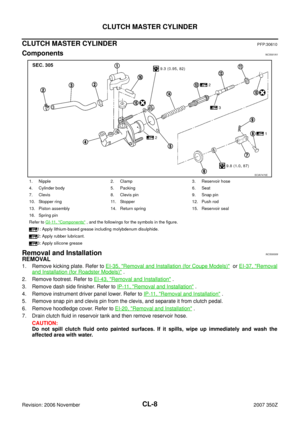
ComponentsNCS001A1
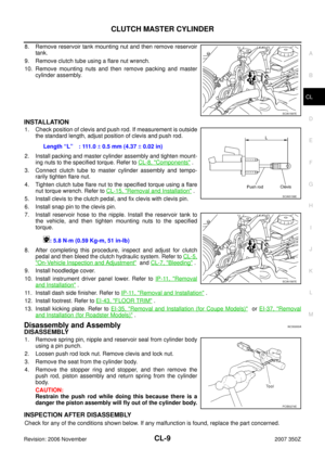
Removal and InstallationNCS00009
REMOVAL
1. Remove kicking plate. Refer to EI-35, "Removal and Installation (for Coupe Models)" or EI-37, "Removal
and Installation (for Roadster Models)" .
2. Remove footrest. Refer to EI-43, "
Removal and Installation" .
3. Remove dash side finisher. Refer to IP-11, "
Removal and Installation" .
4. Remove instrument driver panel lower. Refer to IP-11, "
Removal and Installation" .
5. Remove snap pin and clevis pin from the clevis, and separate it from clutch pedal.
6. Remove hoodledge cover. Refer to EI-20, "
Removal and Installation" .
7. Drain clutch fluid in reservoir tank and then remove reservoir hose.
CAUTION:
Do not spill clutch fluid onto painted surfaces. If it spills, wipe up immediately and wash the
affected area with water.
1. Nipple 2. Clamp 3. Reservoir hose
4. Cylinder body 5. Packing 6. Seat
7. Clevis 8. Clevis pin 9. Snap pin
10. Stopper ring 11. Stopper 12. Push rod
13. Piston assembly 14. Return spring 15. Reservoir seal
16. Spring pin
Refer to GI-11, "
Components" , and the followings for the symbols in the figure.
1: Apply lithium-based grease including molybdenum disulphide.
2: Apply rubber lubricant.
3: Apply silicone grease
SCIA7470E