Page 9 of 20

CLUTCH MASTER CYLINDER
CL-9
D
E
F
G
H
I
J
K
L
MA
B
CL
Revision: 2006 November2007 350Z
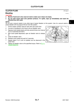
8. Remove reservoir tank mounting nut and then remove reservoir
tank.
9. Remove clutch tube using a flare nut wrench.
10. Remove mounting nuts and then remove packing and master
cylinder assembly.
INSTALLATION
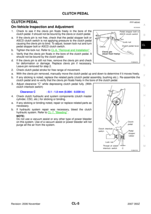
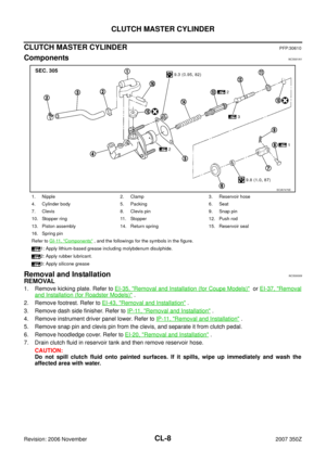
1. Check position of clevis and push rod. If measurement is outside
the standard length, adjust position of clevis and push rod.
2. Install packing and master cylinder assembly and tighten mount-
ing nuts to the specified torque. Refer to CL-8, "
Components" .
3. Connect clutch tube to master cylinder assembly and tempo-
rarily tighten flare nut.
4. Tighten clutch tube flare nut to the specified torque using a flare
nut torque wrench. Refer to CL-15, "
Removal and Installation" .
5. Install clevis to the clutch pedal, and fix clevis with clevis pin.
6. Install snap pin to the clevis pin.
7. Install reservoir hose to the nipple. Install the reservoir tank to
the vehicle, and then tighten mounting nuts to the specified
torque.
8. After completing this procedure, inspect and adjust for clutch
pedal and then bleed the clutch hydraulic system. Refer to CL-5,
"On-Vehicle Inspection and Adjustment" and CL-7, "Bleeding" .
9. Install hoodledge cover.
10. Install instrument driver panel lower. Refer to IP-11, "
Removal
and Installation" .
11. Install dash side finisher. Refer to IP-11, "
Removal and Installation" .
12. Install footrest. Refer to EI-43, "
FLOOR TRIM" .
13. Install kicking plate. Refer to EI-35, "
Removal and Installation (for Coupe Models)" or EI-37, "Removal
and Installation (for Roadster Models)" .
Disassembly and AssemblyNCS0000A
DISASSEMBLY
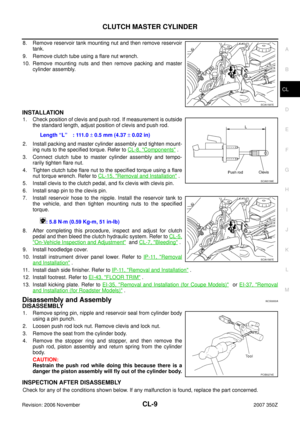
1. Remove spring pin, nipple and reservoir seal from cylinder body
using a pin punch.
2. Loosen push rod lock nut. Remove clevis and lock nut.
3. Remove the seat from the cylinder body.
4. Remove the stopper ring and stopper, and then remove the
push rod, piston assembly and return spring from the cylinder
body.
CAUTION:
Restrain the push rod while doing this because there is a
danger the piston assembly will fly out of the cylinder body.
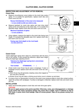
INSPECTION AFTER DISASSEMBLY
Check for any of the conditions shown below. If any malfunction is found, replace the part concerned.
SCIA1587E
Length “L” : 111.0 ± 0.5 mm (4.37 ± 0.02 in)
: 5.8 N·m (0.59 Kg-m, 51 in-lb)
SCIA5158E
SCIA1587E
PCIB0274E
Page 10 of 20

CL-10
CLUTCH MASTER CYLINDER
Revision: 2006 November2007 350Z
�Damaged cylinder internal wall, foreign matter, wear, corrosion, or pin hole
�Damaged or deformed nipple or reservoir tank
�Settling of the spring
�Cracked and deformed seat
ASSEMBLY
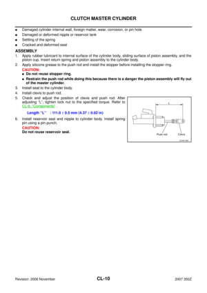
1. Apply rubber lubricant to internal surface of the cylinder body, sliding surface of piston assembly, and the
piston cup. Insert return spring and piston assembly to the cylinder body.
2. Apply silicone grease to the push rod and install the stopper before installing the stopper ring.
CAUTION:
�Do not reuse stopper ring.
�Restrain the push rod while doing this because there is a danger the piston assembly will fly out
of the master cylinder.
3. Install seat to the cylinder body.
4. Install clevis to push rod.
5. Check and adjust the position of clevis and push rod. After
adjusting “L”, tighten lock nut to the specified torque. Refer to
CL-8, "
Components" .
6. Install reservoir seal and nipple to cylinder body. Install spring
pin using a pin punch.
CAUTION:
Do not reuse reservoir seal.Length “L” : 111.0 ± 0.5 mm (4.37 ± 0.02 in)
SCIA5158E
Page 11 of 20
CSC (CONCENTRIC SLAVE CYLINDER)
CL-11
D
E
F
G
H
I
J
K
L
MA
B
CL
Revision: 2006 November2007 350Z
CSC (CONCENTRIC SLAVE CYLINDER)PFP:30500
Removal and InstallationNCS0029M
CAUTION:
�If transmission assembly is removed from the vehicle, always replace CSC (Concentric Slave Cyl-
inder) body and CSC tube. Return CSC body insert to original position to remove transmission
assembly. Dust on clutch disc sliding parts may damage seal of CSC body and may cause clutch
fluid leakage.
�Do not disassemble CSC body.
�Keep painted surface on the body or other parts free of clutch fluid. If it spills, wipe up immediately
and wash the affected area with water.
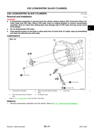
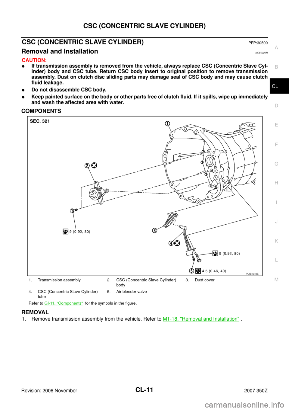
COMPONENTS
REMOVAL
1. Remove transmission assembly from the vehicle. Refer to MT-18, "Removal and Installation" .
1. Transmission assembly 2. CSC (Concentric Slave Cylinder)
body3. Dust cover
4. CSC (Concentric Slave Cylinder)
tube5. Air bleeder valve
Refer to GI-11, "
Components" for the symbols in the figure.
PCIB1940E
Page 12 of 20
CL-12
CSC (CONCENTRIC SLAVE CYLINDER)
Revision: 2006 November2007 350Z
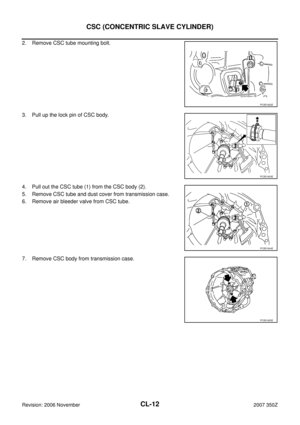
2. Remove CSC tube mounting bolt.
3. Pull up the lock pin of CSC body.
4. Pull out the CSC tube (1) from the CSC body (2).
5. Remove CSC tube and dust cover from transmission case.
6. Remove air bleeder valve from CSC tube.
7. Remove CSC body from transmission case.
PCIB1902E
PCIB1903E
PCIB1904E
PCIB1905E
Page 13 of 20
CSC (CONCENTRIC SLAVE CYLINDER)
CL-13
D
E
F
G
H
I
J
K
L
MA
B
CL
Revision: 2006 November2007 350Z
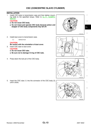
INSTALLATION
1. Install CSC body to transmission case and then tighten mount-
ing bolts to the specified torque. Refer to CL-11, "
COMPO-
NENTS" .
CAUTION:
�Do not reuse CSC body.
�Do not insert and operate CSC body because piston and
stopper of CSC body components may fall off.
2. Install dust cover to transmission case.
CAUTION:
Be careful with the orientation of dust cover.
3. Insert CSC tube to dust cover.
CAUTION:
�Do not reuse CSC tube.
�Be sure not to damage O-ring of CSC tube.
4. Press down the lock pin of the CSC body.
5. Insert the CSC tube (1) into the connector of the CSC body (2)
until it clicks.
PCIB1905E
: Vehicle front
PCIB1906E
PCIB1907E
PCIB1904E
Page 14 of 20
CL-14
CSC (CONCENTRIC SLAVE CYLINDER)
Revision: 2006 November2007 350Z
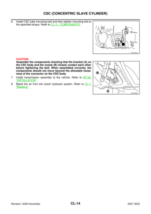
6. Install CSC tube mounting bolt and then tighten mounting bolt to
the specified torque. Refer to CL-11, "
COMPONENTS" .
CAUTION:
Assemble the components checking that the bracket (A) on
the CSC body and the nozzle (B) closely contact each other
before tightening the bolt. When assembled correctly, the
components should not move beyond the allowable loose-
ness of the connector on the CSC body.
7. Install transmission assembly to the vehicle. Refer to MT-20,
"INSTALLATION" .
8. Bleed the air from the clutch hydraulic system, Refer to CL-7,
"Bleeding" .
PCIB1902E
PCIB1908E
Page 15 of 20

CLUTCH PIPING
CL-15
D
E
F
G
H
I
J
K
L
MA
B
CL
Revision: 2006 November2007 350Z
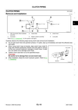
CLUTCH PIPINGPFP:30650
Removal and InstallationNCS0000D
Carefully observe the following steps during clutch tube removal and installation.
�Do not spill clutch fluid onto painted surfaces. If it spills, wipe up immediately and wash the affected area
with water.
�When fixing clutch hose to bracket, align clutch hose metal fit-
tings with bracket positioning emboss and lock plate to secure.
At this time, prevent twisting or damage of clutch hose. In addi-
tion, be careful not to damage clutch hose.
�Tighten clutch tube flare nut to the specified torque.
CAUTION:
Be careful not to damage flare nut and clutch tube.
�After installation, bleed the clutch hydraulic system. Refer to CL-
7, "Bleeding" .
1. CSC (Concentric Slave Cylinder)
assembly2. Clutch tube 3. Clutch hose
4. Connector 5. Master cylinder assembly 6. Lock plate
Refer to GI-11, "
Components" , for the symbol in the figure.
PCIB1922E
PCIB0681E
Page 16 of 20

CL-16
CLUTCH DISC, CLUTCH COVER
Revision: 2006 November2007 350Z
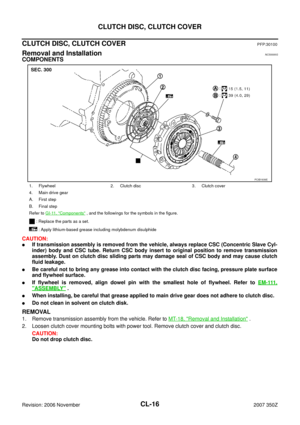
CLUTCH DISC, CLUTCH COVERPFP:30100
Removal and InstallationNCS0000G
COMPONENTS
CAUTION:
�If transmission assembly is removed from the vehicle, always replace CSC (Concentric Slave Cyl-
inder) body and CSC tube. Return CSC body insert to original position to remove transmission
assembly. Dust on clutch disc sliding parts may damage seal of CSC body and may cause clutch
fluid leakage.
�Be careful not to bring any grease into contact with the clutch disc facing, pressure plate surface
and flywheel surface.
�If flywheel is removed, align dowel pin with the smallest hole of flywheel. Refer to EM-111,
"ASSEMBLY" .
�When installing, be careful that grease applied to main drive gear does not adhere to clutch disc.
�Do not clean in solvent on clutch disk.
REMOVAL
1. Remove transmission assembly from the vehicle. Refer to MT-18, "Removal and Installation" .
2. Loosen clutch cover mounting bolts with power tool. Remove clutch cover and clutch disc.
CAUTION:
Do not drop clutch disc.
1. Flywheel 2. Clutch disc 3. Clutch cover
4. Main drive gear
A. First step
B. Final step
Refer to GI-11, "
Components" , and the followings for the symbols in the figure.
: Replace the parts as a set.
: Apply lithium-based grease including molybdenum disulphide
PCIB1939E


Revision: 2006 November2007 350Z
2. Remove CSC tube mounting bolt.
3. Pull up the lock pin of CSC body.
4. Pull out the CSC tube (1) from the CSC body (2).
5. Rem")

CL-13
D
E
F
G
H
I
J
K
L
MA
B
CL
Revision: 2006 November2007 350Z
INSTALLATION
1. Install CSC body to transmission case and then tighten mount-
ing bolts to the specifie")

Revision: 2006 November2007 350Z
6. Install CSC tube mounting bolt and then tighten mounting bolt to
the specified torque. Refer to CL-11, \"
COMPONENTS\" .
CAUTION")