Page 78 of 260
BL-78
REMOTE KEYLESS ENTRY SYSTEM
Revision: 2006 November2007 350Z
Check ACC Switch NIS0001L
1. CHECK ACC SWITCH
With CONSULT-III
Check ACC switch (“ACC ON SW”) in “DATA MONITOR” mode with CONSULT-III.
Without CONSULT-III
Check voltage between BCM connector and ground.
OK or NG
OK >> ACC switch is OK.
NG >> Check the following.
�10A fuse [No. 6, located in fuse block (J/B)]
�Harness for open or short between BCM and fuse
Monitor item Condition
ACC ON SWIgnition switch position is ACC or ON : ON
Ignition switch position is OFF : OFF
ItemCon-
nectorTerminals
(Wire color)
ConditionVoltage [V]
(Approx.)
(+) (–)
Ignition switch M90 11 (LG) GroundACC or ON Battery voltage
OFF 0
PIIA7002E
Page 80 of 260
BL-80
REMOTE KEYLESS ENTRY SYSTEM
Revision: 2006 November2007 350Z
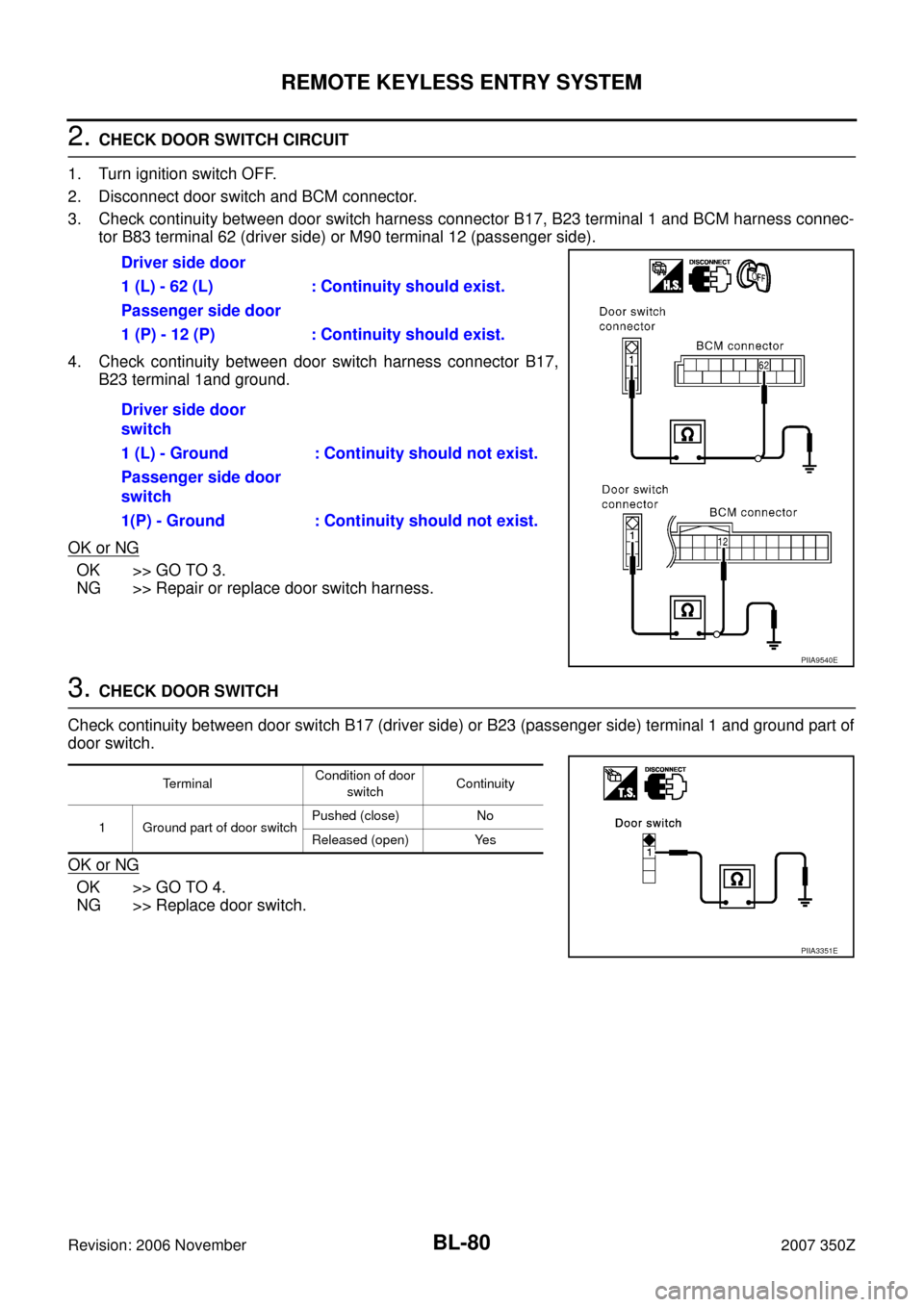
2. CHECK DOOR SWITCH CIRCUIT
1. Turn ignition switch OFF.
2. Disconnect door switch and BCM connector.
3. Check continuity between door switch harness connector B17, B23 terminal 1 and BCM harness connec-
tor B83 terminal 62 (driver side) or M90 terminal 12 (passenger side).
4. Check continuity between door switch harness connector B17,
B23 terminal 1and ground.
OK or NG
OK >> GO TO 3.
NG >> Repair or replace door switch harness.
3. CHECK DOOR SWITCH
Check continuity between door switch B17 (driver side) or B23 (passenger side) terminal 1 and ground part of
door switch.
OK or NG
OK >> GO TO 4.
NG >> Replace door switch.Driver side door
1 (L) - 62 (L) : Continuity should exist.
Passenger side door
1 (P) - 12 (P) : Continuity should exist.
Driver side door
switch
1 (L) - Ground : Continuity should not exist.
Passenger side door
switch
1(P) - Ground : Continuity should not exist.
PIIA9540E
TerminalCondition of door
switchContinuity
1 Ground part of door switchPushed (close) No
Released (open) Yes
PIIA3351E
Page 81 of 260
REMOTE KEYLESS ENTRY SYSTEM
BL-81
C
D
E
F
G
H
J
K
L
MA
B
BL
Revision: 2006 November2007 350Z
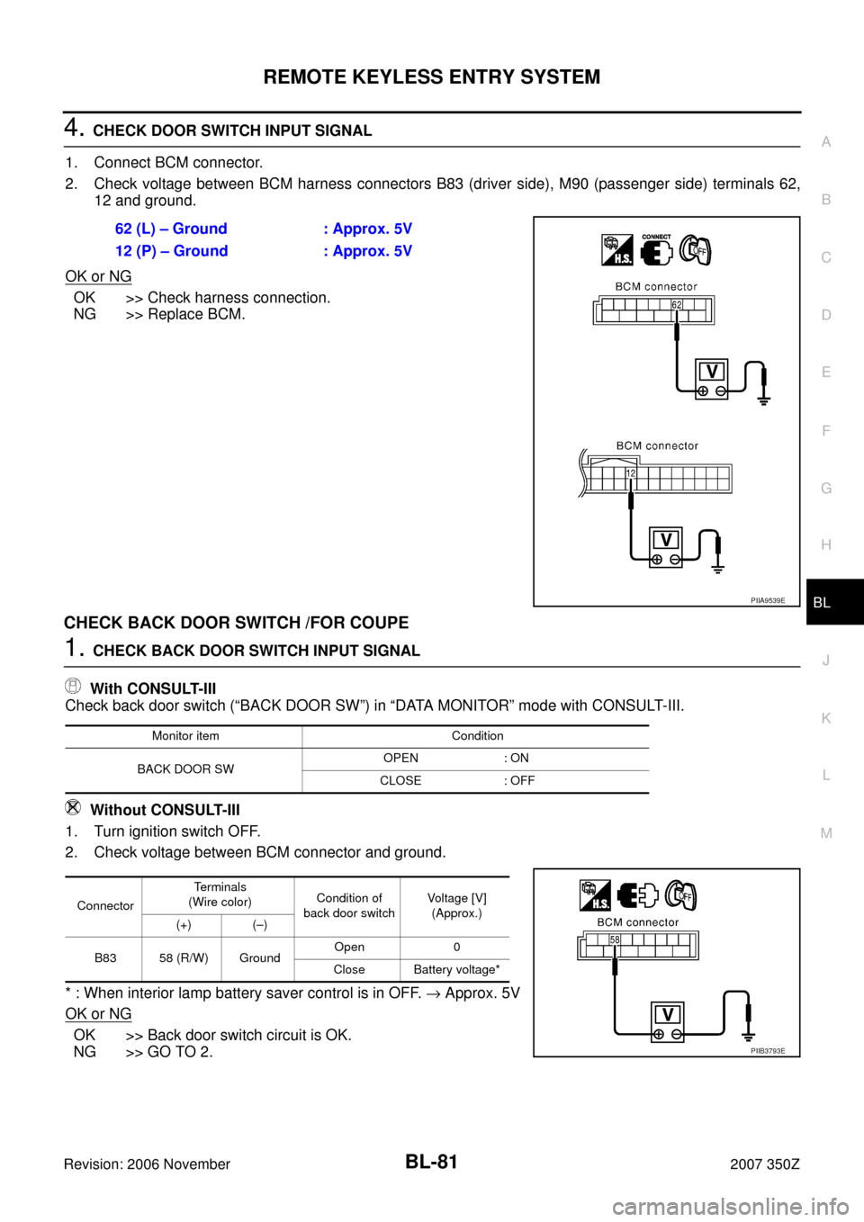
4. CHECK DOOR SWITCH INPUT SIGNAL
1. Connect BCM connector.
2. Check voltage between BCM harness connectors B83 (driver side), M90 (passenger side) terminals 62,
12 and ground.
OK or NG
OK >> Check harness connection.
NG >> Replace BCM.
CHECK BACK DOOR SWITCH /FOR COUPE
1. CHECK BACK DOOR SWITCH INPUT SIGNAL
With CONSULT-III
Check back door switch (“BACK DOOR SW”) in “DATA MONITOR” mode with CONSULT-III.
Without CONSULT-III
1. Turn ignition switch OFF.
2. Check voltage between BCM connector and ground.
* : When interior lamp battery saver control is in OFF. → Approx. 5V
OK or NG
OK >> Back door switch circuit is OK.
NG >> GO TO 2.62 (L) – Ground : Approx. 5V
12 (P) – Ground : Approx. 5V
PIIA9539E
Monitor item Condition
BACK DOOR SWOPEN : ON
CLOSE : OFF
ConnectorTerminals
(Wire color)Condition of
back door switchVoltage [V]
(Approx.)
(+) (–)
B83 58 (R/W) GroundOpen 0
Close Battery voltage*
PIIB3793E
Page 82 of 260
BL-82
REMOTE KEYLESS ENTRY SYSTEM
Revision: 2006 November2007 350Z
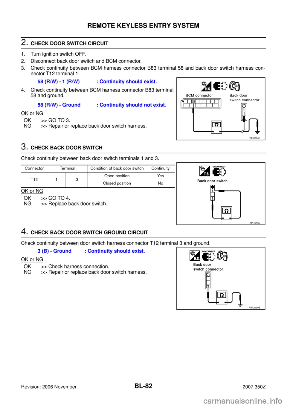
2. CHECK DOOR SWITCH CIRCUIT
1. Turn ignition switch OFF.
2. Disconnect back door switch and BCM connector.
3. Check continuity between BCM harness connector B83 terminal 58 and back door switch harness con-
nector T12 terminal 1.
4. Check continuity between BCM harness connector B83 terminal
58 and ground.
OK or NG
OK >> GO TO 3.
NG >> Repair or replace back door switch harness.
3. CHECK BACK DOOR SWITCH
Check continuity between back door switch terminals 1 and 3.
OK or NG
OK >> GO TO 4.
NG >> Replace back door switch.
4. CHECK BACK DOOR SWITCH GROUND CIRCUIT
Check continuity between door switch harness connector T12 terminal 3 and ground.
OK or NG
OK >> Check harness connection.
NG >> Repair or replace back door switch harness.58 (R/W) - 1 (R/W) : Continuity should exist.
58 (R/W) - Ground : Continuity should not exist.
PIIB3794E
Connector Terminal Condition of back door switch Continuity
T12 1 3Open position Yes
Closed position No
PIIA4316E
3 (B) - Ground : Continuity should exist.
PIIA2490E
Page 83 of 260
REMOTE KEYLESS ENTRY SYSTEM
BL-83
C
D
E
F
G
H
J
K
L
MA
B
BL
Revision: 2006 November2007 350Z
Check Trunk Lid Lock Assembly (Trunk Room Lamp Switch) / For RoadsterNIS0001N
1. CHECK TRUNK LID LOCK ASSEMBLY (TRUNK ROOM LAMP SWITCH) INPUT SIGNAL
With CONSULT-III
Check trunk lid opener switch (“TRUNK OPN MNTR”) in “DATA MONITOR” mode with CONSULT-III.
Without CONSULT-III
Check voltage between BCM connector and ground.
*: When interior lamp battery saver control is in OFF. → Approx. 5V.
OK or NG
OK >> Trunk room lamp switch is OK.
NG >> GO TO 2.
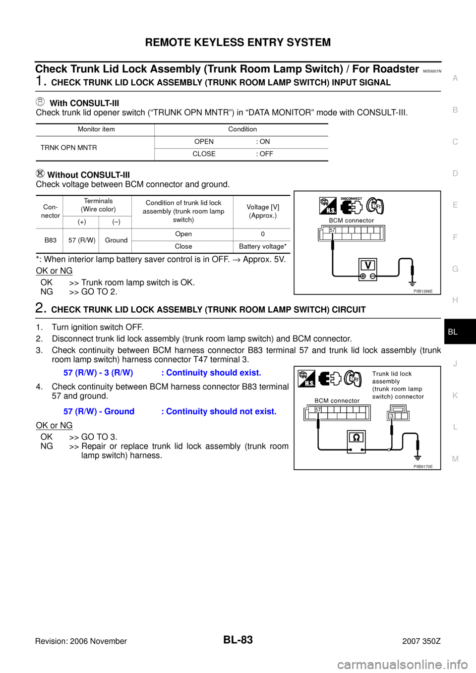
2. CHECK TRUNK LID LOCK ASSEMBLY (TRUNK ROOM LAMP SWITCH) CIRCUIT
1. Turn ignition switch OFF.
2. Disconnect trunk lid lock assembly (trunk room lamp switch) and BCM connector.
3. Check continuity between BCM harness connector B83 terminal 57 and trunk lid lock assembly (trunk
room lamp switch) harness connector T47 terminal 3.
4. Check continuity between BCM harness connector B83 terminal
57 and ground.
OK or NG
OK >> GO TO 3.
NG >> Repair or replace trunk lid lock assembly (trunk room
lamp switch) harness.
Monitor item Condition
TRNK OPN MNTROPEN : ON
CLOSE : OFF
Con-
nectorTe r m i n a l s
(Wire color)Condition of trunk lid lock
assembly (trunk room lamp
switch)Voltage [V]
(Approx.)
(+) (–)
B83 57 (R/W) GroundOpen 0
Close Battery voltage*
PIIB1266E
57 (R/W) - 3 (R/W) : Continuity should exist.
57 (R/W) - Ground : Continuity should not exist.
PIIB9170E
Page 84 of 260
BL-84
REMOTE KEYLESS ENTRY SYSTEM
Revision: 2006 November2007 350Z
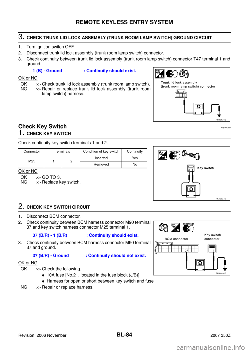
3. CHECK TRUNK LID LOCK ASSEMBLY (TRUNK ROOM LAMP SWITCH) GROUND CIRCUIT
1. Turn ignition switch OFF.
2. Disconnect trunk lid lock assembly (trunk room lamp switch) connector.
3. Check continuity between trunk lid lock assembly (trunk room lamp switch) connector T47 terminal 1 and
ground.
OK or NG
OK >> Check trunk lid lock assembly (trunk room lamp switch).
NG >> Repair or replace trunk lid lock assembly (trunk room
lamp switch) harness.
Check Key Switch NIS0001O
1. CHECK KEY SWITCH
Check continuity key switch terminals 1 and 2.
OK or NG
OK >> GO TO 3.
NG >> Replace key switch.
2. CHECK KEY SWITCH CIRCUIT
1. Disconnect BCM connector.
2. Check continuity between BCM harness connector M90 terminal
37 and key switch harness connector M25 terminal 1.
3. Check continuity between BCM harness connector M90 terminal
37 and ground.
OK or NG
OK >> Check the following.
�10A fuse [No.21, located in the fuse block (J/B)]
�Harness for open or short between key switch and fuse
NG >> Repair or replace harness.1 (B) - Ground : Continuity should exist.
PIIB9171E
Connector Terminals Condition of key switch Continuity
M25 1 2Inserted Yes
Removed No
PIIA2627E
37 (B/R) - 1 (B/R) : Continuity should exist.
37 (B/R) - Ground : Continuity should not exist.
PIIB1258E
Page 85 of 260
REMOTE KEYLESS ENTRY SYSTEM
BL-85
C
D
E
F
G
H
J
K
L
MA
B
BL
Revision: 2006 November2007 350Z
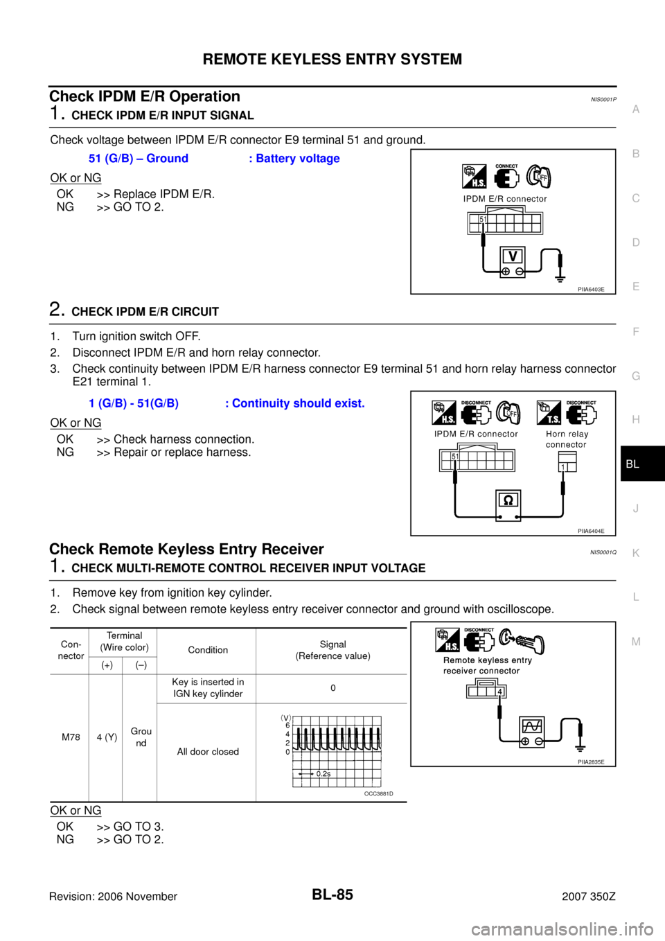
Check IPDM E/R Operation NIS0001P
1. CHECK IPDM E/R INPUT SIGNAL
Check voltage between IPDM E/R connector E9 terminal 51 and ground.
OK or NG
OK >> Replace IPDM E/R.
NG >> GO TO 2.
2. CHECK IPDM E/R CIRCUIT
1. Turn ignition switch OFF.
2. Disconnect IPDM E/R and horn relay connector.
3. Check continuity between IPDM E/R harness connector E9 terminal 51 and horn relay harness connector
E21 terminal 1.
OK or NG
OK >> Check harness connection.
NG >> Repair or replace harness.
Check Remote Keyless Entry Receiver NIS0001Q
1. CHECK MULTI-REMOTE CONTROL RECEIVER INPUT VOLTAGE
1. Remove key from ignition key cylinder.
2. Check signal between remote keyless entry receiver connector and ground with oscilloscope.
OK or NG
OK >> GO TO 3.
NG >> GO TO 2.51 (G/B) – Ground : Battery voltage
PIIA6403E
1 (G/B) - 51(G/B) : Continuity should exist.
PIIA6404E
Con-
nectorTerminal
(Wire color)
Condition Signal
(Reference value)
(+) (–)
M78 4 (Y)Grou
ndKey is inserted in
IGN key cylinder 0
All door closed
PIIA2835E
OCC3881D
Page 86 of 260
BL-86
REMOTE KEYLESS ENTRY SYSTEM
Revision: 2006 November2007 350Z
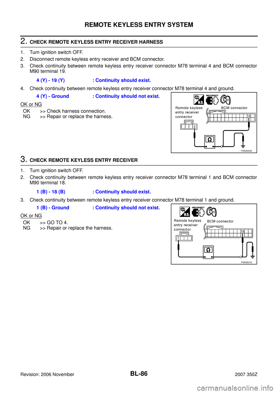
2. CHECK REMOTE KEYLESS ENTRY RECEIVER HARNESS
1. Turn ignition switch OFF.
2. Disconnect remote keyless entry receiver and BCM connector.
3. Check continuity between remote keyless entry receiver connector M78 terminal 4 and BCM connector
M90 terminal 19.
4. Check continuity between remote keyless entry receiver connector M78 terminal 4 and ground.
OK or NG
OK >> Check harness connection.
NG >> Repair or replace the harness.
3. CHECK REMOTE KEYLESS ENTRY RECEIVER
1. Turn ignition switch OFF.
2. Check continuity between remote keyless entry receiver connector M78 terminal 1 and BCM connector
M90 terminal 18.
3. Check continuity between remote keyless entry receiver connector M78 terminal 1 and ground.
OK or NG
OK >> GO TO 4.
NG >> Repair or replace the harness.4 (Y) - 19 (Y) : Continuity should exist.
4 (Y) - Ground : Continuity should not exist.
PIIA9630E
1 (B) - 18 (B) : Continuity should exist.
1 (B) - Ground : Continuity should not exist.
PIIA9631E