Page 409 of 1449
ENGINE <4G6> -General Information11A-3
GENERAL INFORMATION
Items4G63
Total displacement mL1,997
Bore×Stroke mm85.0×88.0
Compression ratio8.8
Combustion chamberPentroof type
Camshaft arrangementDOHC
Number of valveIntake8
Exhaust8
Valve timingIntakeOpeningBTDC 21_
ClosingABDC 59_
ExhaustOpeningBBDC 58_
ClosingATDC 18_
Fuel systemElectronically controlled multipoint fuel injection
Rocker armRoller type
Auto-lash adjusterEquipped
Page 410 of 1449

ENGINE -Service Specifications/Sealants11A-4
SERVICE SPECIFICATIONS
ItemsStandard valueLimit
Drive belt tensionVibration frequency Hz (Reference)110 - 144-
Tension N (Reference)245 - 412-
Basic ignition timing5_BTDC±3_-
Ignition timingApproximetely
5_BTDC-
Idle speed r/min850±100-
CO contents %0.1 or less-
HC contents ppm100 or less-
Compression pressure (250 - 400 r/min) kPa1,128951
Compression pressure difference of all cylinder kPa-Max. 98
Intake manifold vacuum kPa-Min. 60
Cylinder head bolt shank length mm-99.4
Timing belt B tension
(Whenchecked)
Vibration frequency Hz52 - 92-
(When checked)Deflection mm (Reference)5-10-
Timing belt B tension
(Whenadjusted)
Vibration frequency Hz76 - 92-
(When adjusted)Deflection mm (Reference)5-7-
Timing belt B tension
(Whenreplaced)
Vibration frequency Hz76 - 92-
(When replaced)Deflection mm (Reference)5-7-
Auto-tensioner rod protrusion amount mm3.8 - 4.5-
Auto-tensioner rod sink in amount mmWithin 1-
SEALANTS
ItemsSpecified SealantsRemarks
Rocker coverMITSUBISHI GENUINE PART MD970389 or
equivalent
Semi-drying
sealant
Rocker cover gasket
equivalentsealant
Cylinder head
Camshaft position sensor support
Oil pan
Camshaft end seal3M ATD Part No. 8660 or equivalent
Page 419 of 1449

ENGINE -On-vehicle Service11A-13
(2) If there is a problem with the lash adjusters, the noise
will almost never disappear, even if the engine has
been run at idle to let it warm up.
The only case where the noise might disappear is
if the oil in the engine has not been looked after
properly and oil sludge has caused the lash adjusters
to stick.
1. Start the engine.
2. Check that the noise occurs immediately after the engine
is started, and that the noise changes in accordance
with changes in the engine speed.
If the noise does not occur immediately after the engine
is started, or if it does not change in accordance with
the engine speed, the problem is not being caused by
the lash adjusters, so check for some other cause of
the problem. Moreover, if the noise does not change in
accordance with the engine speed, the cause of the
problem is probably not with the engine. (In these cases,
the lash adjusters are normal.)
3. While the engine is idling, check that the noise level does
not change when the engine load is varied.
If the noise level changes, the cause of the noise is
probably parts striking because of worn crankshaft
bearings or connecting rod bearings. (In such cases, the
lash adjusters are normal.)
4. After the engine has warmed up, run it at idle and check
if any noise can be heard.
If the noise has become smaller or disappeared, oil sludge
could make the lash adjusters stick. Clean the lash
adjusters. (Refer to the Engine Workshop Manual.) If not
improved, go to step 5.
5. Bleed air from the lash adjusters.
6. If the noise has not disappeared even after the air
bleeding, clean the lash adjusters.
(Refer to GROUP 11B - Rocker Arms and Camshaft.)
NOTE
(1) If the vehicle is parked on a slope for a long period
of time, the amount of oil inside the lash adjuster
will decrease, and air may get into the high pressure
chamber when starting the engine.
(2) After parking the vehicle for long periods, the oil drains
out of the oil passage, and it takes time for the oil
to be supplied to the lash adjuster, so air can get
into the high pressure chamber.
(3) If either of the above situations occur, the abnormal
noise can be eliminated by bleeding the air from inside
the lash adjusters.
Page 423 of 1449
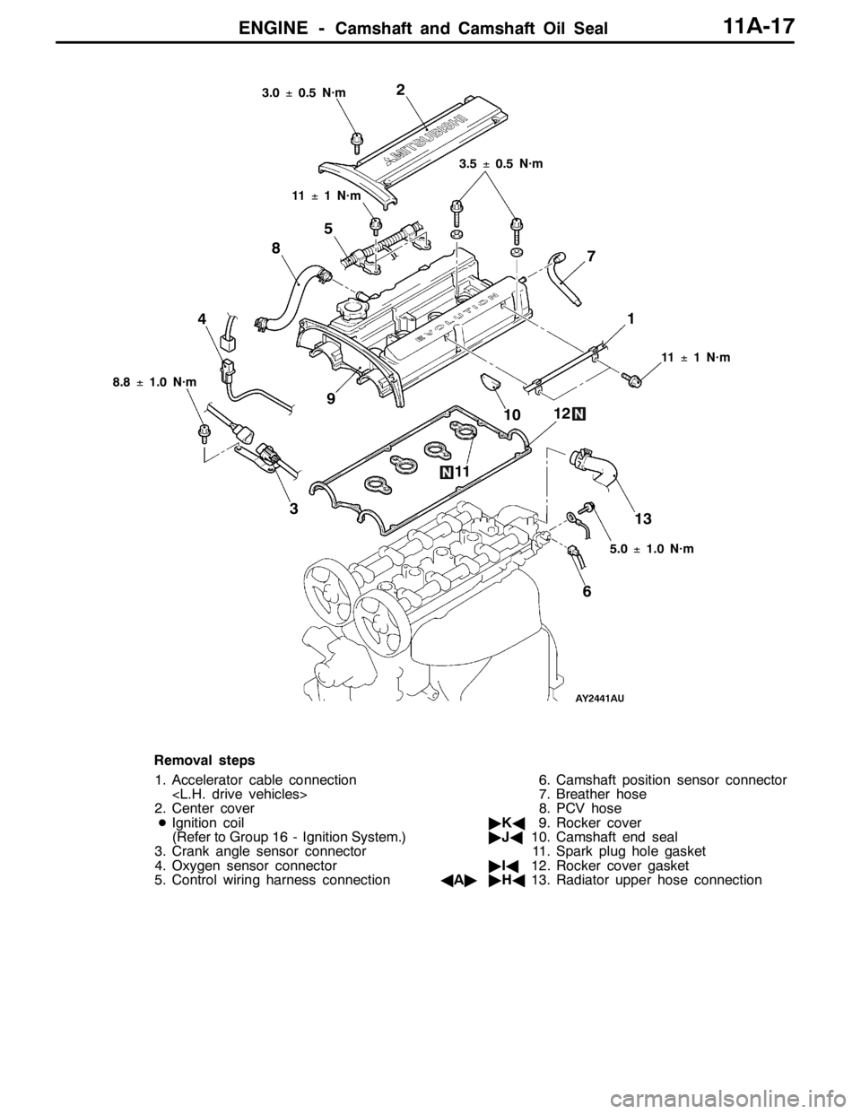
ENGINE -Camshaft and Camshaft Oil Seal11A-17
2
3 45
67 8
9
1012
11
11±1 N·m
8.8±1.0 N·m3.5±0.5 N·m
5.0±1.0 N·m
13
3.0±0.5 N·m
1
11±1 N·m
Removal steps
1. Accelerator cable connection
2. Center cover
DIgnition coil
(Refer to Group 16 - Ignition System.)
3. Crank angle sensor connector
4. Oxygen sensor connector
5. Control wiring harness connection6. Camshaft position sensor connector
7. Breather hose
8. PCV hose
"KA9. Rocker cover
"JA10. Camshaft end seal
11. Spark plug hole gasket
"IA12. Rocker cover gasket
AA""HA13. Radiator upper hose connection
Page 424 of 1449
ENGINE -Camshaft and Camshaft Oil Seal11A-18
Apply engine oil to all
sliding parts at the time
of installation.
10±2 N·m
89±9 N·m20±1 N·m
22±4 N·m
14±1 N·m
28
29 27 26
20
14 15
16
17 19
18222321
2425
11±1 N·m
30
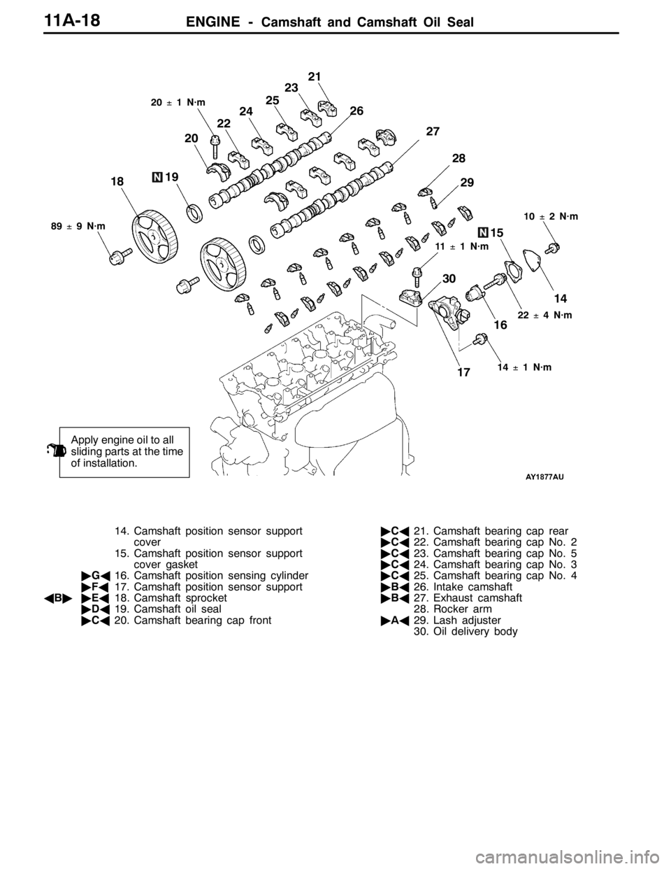
14. Camshaft position sensor support
cover
15. Camshaft position sensor support
cover gasket
"GA16. Camshaft position sensing cylinder
"FA17. Camshaft position sensor support
AB""EA18. Camshaft sprocket
"DA19. Camshaft oil seal
"CA20. Camshaft bearing cap front"CA21. Camshaft bearing cap rear
"CA22. Camshaft bearing cap No. 2
"CA23. Camshaft bearing cap No. 5
"CA24. Camshaft bearing cap No. 3
"CA25. Camshaft bearing cap No. 4
"BA26. Intake camshaft
"BA27. Exhaust camshaft
28. Rocker arm
"AA29. Lash adjuster
30. Oil delivery body
Page 425 of 1449
ENGINE -Camshaft and Camshaft Oil Seal11A-19
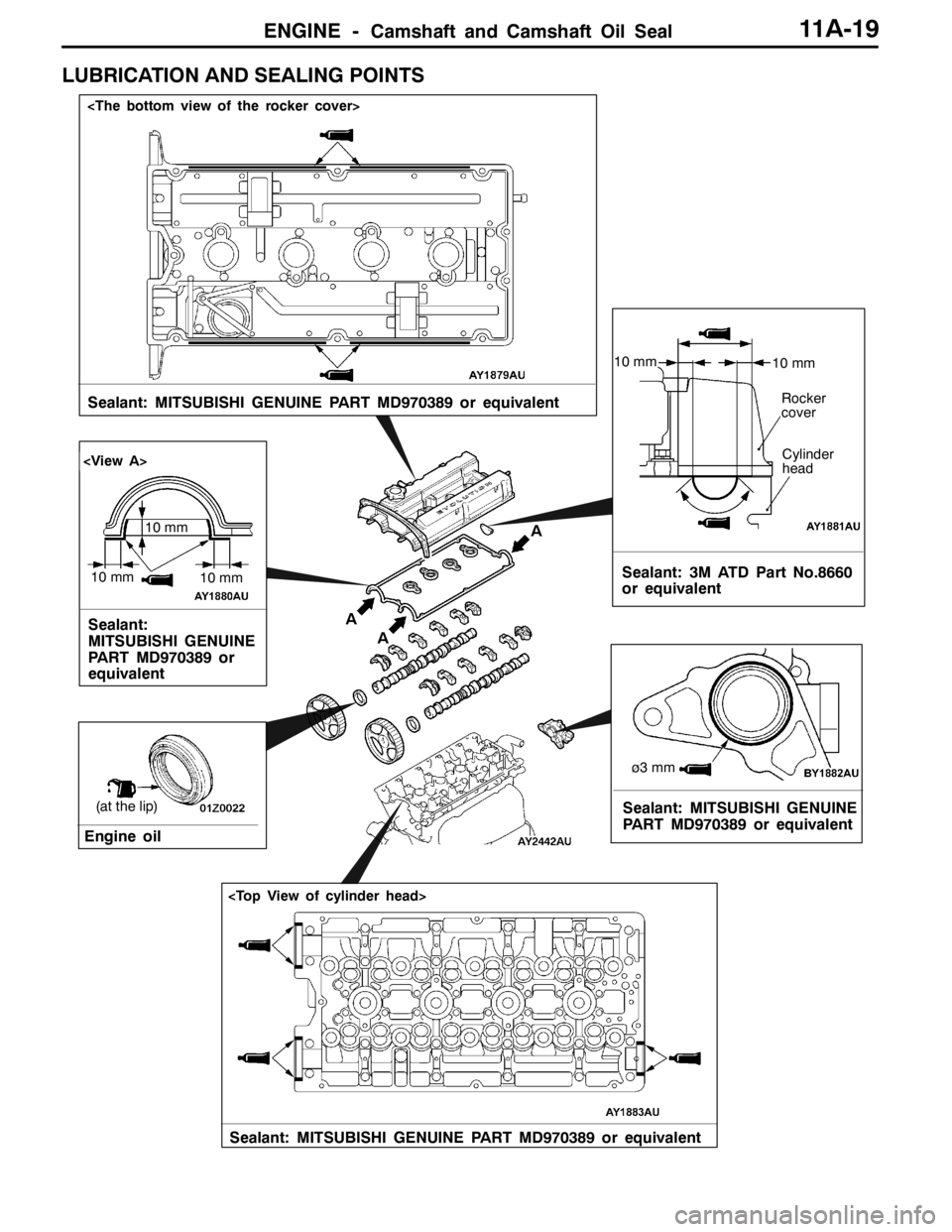
LUBRICATION AND SEALING POINTS
10 mm
10 mm
Sealant: MITSUBISHI GENUINE PART MD970389 or equivalent
(at the lip)
Engine oil
10 mm
Sealant: MITSUBISHI GENUINE
PART MD970389 or equivalent
Sealant: MITSUBISHI GENUINE PART MD970389 or equivalent
Sealant:
MITSUBISHI GENUINE
PART MD970389 or
equivalent
10 mm
10 mm
AA
A
Rocker
cover
Cylinder
head
ø3 mm
Sealant: 3M ATD Part No.8660
or equivalent
Page 426 of 1449
ENGINE -Camshaft and Camshaft Oil Seal11A-20
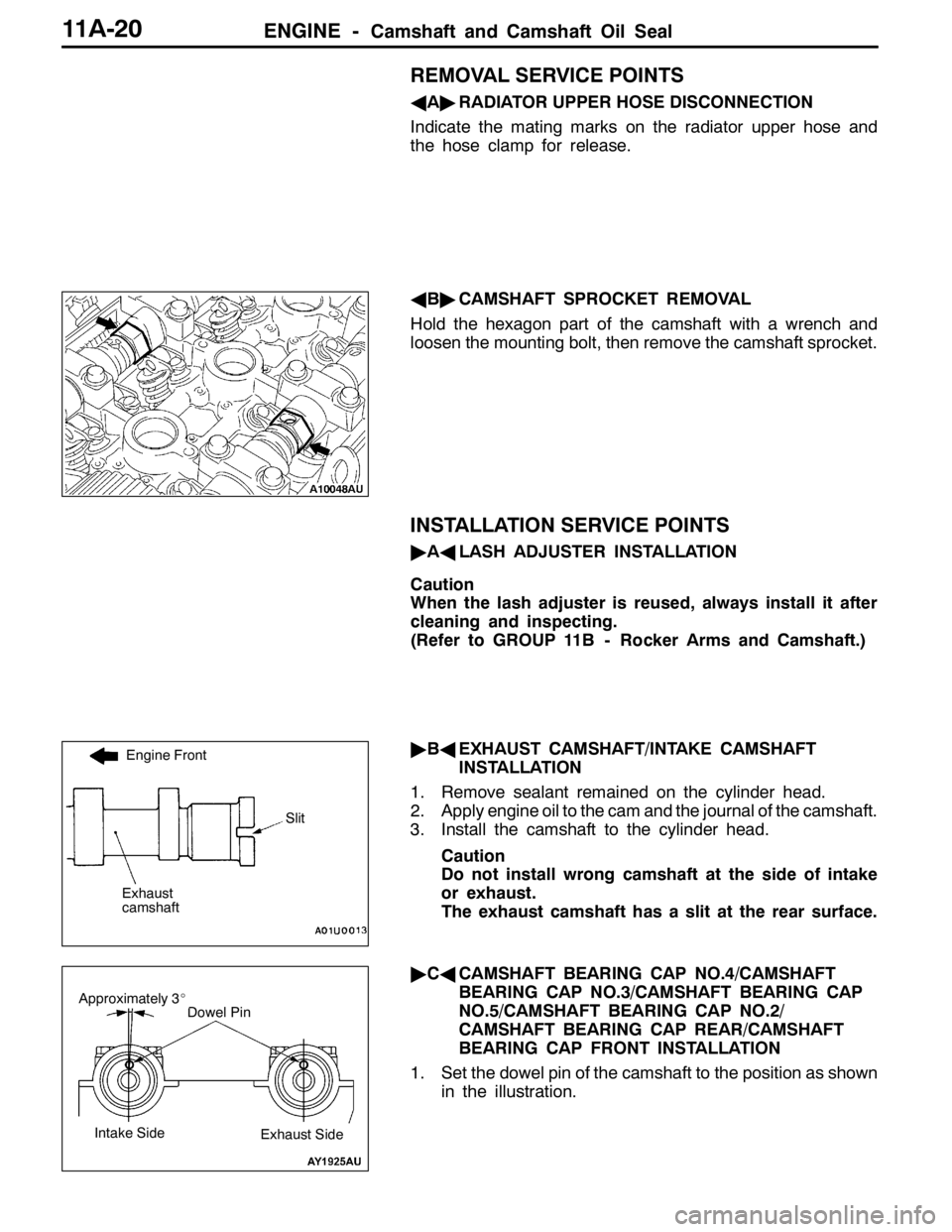
REMOVAL SERVICE POINTS
AA"RADIATOR UPPER HOSE DISCONNECTION
Indicate the mating marks on the radiator upper hose and
the hose clamp for release.
AB"CAMSHAFT SPROCKET REMOVAL
Hold the hexagon part of the camshaft with a wrench and
loosen the mounting bolt, then remove the camshaft sprocket.
INSTALLATION SERVICE POINTS
"AALASH ADJUSTER INSTALLATION
Caution
When the lash adjuster is reused, always install it after
cleaning and inspecting.
(Refer to GROUP 11B - Rocker Arms and Camshaft.)
"BAEXHAUST CAMSHAFT/INTAKE CAMSHAFT
INSTALLATION
1. Remove sealant remained on the cylinder head.
2. Apply engine oil to the cam and the journal of the camshaft.
3. Install the camshaft to the cylinder head.
Caution
Do not install wrong camshaft at the side of intake
or exhaust.
The exhaust camshaft has a slit at the rear surface.
"CACAMSHAFT BEARING CAP NO.4/CAMSHAFT
BEARING CAP NO.3/CAMSHAFT BEARING CAP
NO.5/CAMSHAFT BEARING CAP NO.2/
CAMSHAFT BEARING CAP REAR/CAMSHAFT
BEARING CAP FRONT INSTALLATION
1. Set the dowel pin of the camshaft to the position as shown
in the illustration.
Engine Front
Exhaust
camshaft
Slit
Dowel PinApproximately 3_
Intake SideExhaust Side
Page 427 of 1449
ENGINE -Camshaft and Camshaft Oil Seal11A-21
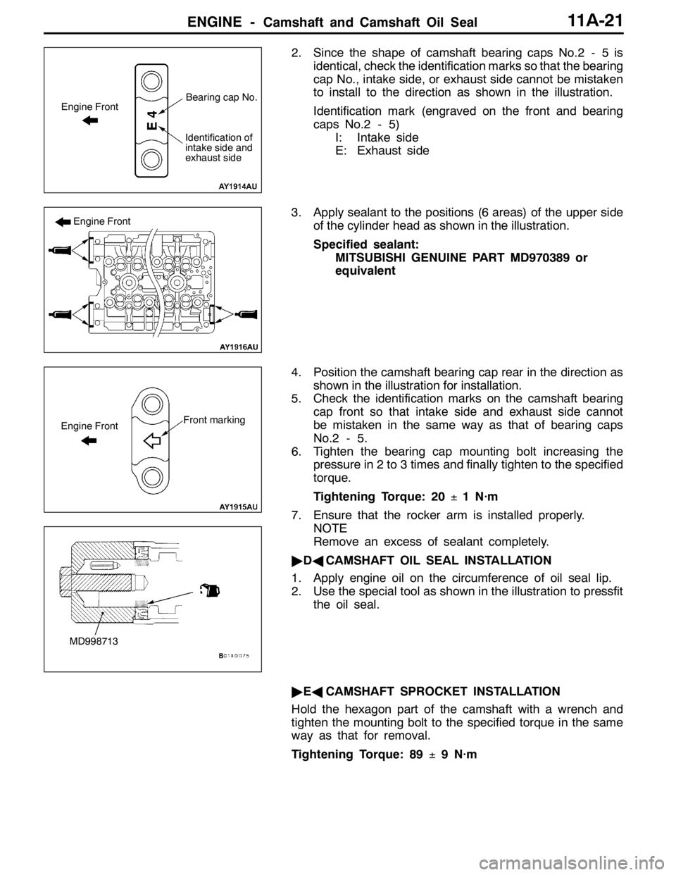
2. Since the shape of camshaft bearing caps No.2 - 5 is
identical, check the identification marks so that the bearing
cap No., intake side, or exhaust side cannot be mistaken
to install to the direction as shown in the illustration.
Identification mark (engraved on the front and bearing
caps No.2 - 5)
I: Intake side
E: Exhaust side
3. Apply sealant to the positions (6 areas) of the upper side
of the cylinder head as shown in the illustration.
Specified sealant:
MITSUBISHI GENUINE PART MD970389 or
equivalent
4. Position the camshaft bearing cap rear in the direction as
shown in the illustration for installation.
5. Check the identification marks on the camshaft bearing
cap front so that intake side and exhaust side cannot
be mistaken in the same way as that of bearing caps
No.2 - 5.
6. Tighten the bearing cap mounting bolt increasing the
pressure in 2 to 3 times and finally tighten to the specified
torque.
Tightening Torque: 20±1 N·m
7. Ensure that the rocker arm is installed properly.
NOTE
Remove an excess of sealant completely.
"DACAMSHAFT OIL SEAL INSTALLATION
1. Apply engine oil on the circumference of oil seal lip.
2. Use the special tool as shown in the illustration to pressfit
the oil seal.
"EACAMSHAFT SPROCKET INSTALLATION
Hold the hexagon part of the camshaft with a wrench and
tighten the mounting bolt to the specified torque in the same
way as that for removal.
Tightening Torque: 89±9 N·m
Engine FrontBearing cap No.
Identification of
intake side and
exhaust side
Engine Front
Front markingEngine Front
MD998713