Page 5 of 1449

BODY CONSTRUCTION -Body ComponentsA-3
1. Headlamp support panel
2. Hood lock stay
3. Front end crossmember
4. Front end upper bar
5. Headlamp support panel side
6. Front fender shield
7. Front upper frame inner
8. Upper frame bulkhead front
9. Upper frame bulkhead
10. Upper frame bulkhead rear
11. Front sidemember inner
12. Engine mount bracket
13. Front sidemember rear
14. Front sidemember outer
15. Spring house panel
16. Dash panel
17. Dash panel silencer
18. Dash panel reinforcement
19. Upper frame to front pillar brace
20. Upper frame extension outer
21. Upper frame extension inner
22. Cowl top lower panel
23. Cowl top inner panel
24. Cowl top upper panel
25. Front deck crossmember
26. Hood inner panel
27. Hood outer panel
28. Front roof rail
29. Front roof bow
30. Roof panel
31. Rear roof bow
32. Rear roof rail
33. Seat back plate
34. Rear seat back panel
35. Rear shelf panel
36. Rear seat back brace
37. Trunk lid outer panel
38. Trunk lid inner panel
39. Trunk lid hinge
40. Quarter inner extension rear
41. Quarter corner panel42. Rear combination lamp housing
43. Side roof rail inner
44. Front pillar inner upper
45. Front pillar inner lower
46. Center pillar inner
47. Side outer panel
48. Rear wheel house inner panel
49. Quarter inner panel
50. Rear floor side brace
51. Quarter outer extension lower
52. Fuel filler door
53. Rear license plate bracket
54. Rear end panel outer
55. Rear end panel inner
56. Rear door outer panel
57. Rear door side door beam
58. Rear door inner panel
59. Front door outer panel
60. Front door side door beam
61. Front door inner panel
62. Fender panel
63. Front floor crossmember rear
64. Front floor crossmember front
65. Front floor side sill inner
66. Front floor sidemember
67. Backbone reinforcement
68. Installment panel center bracket reinforcement
69. Front floor pan
70. Front floor extension panel rear
71. Rear floor extension
72. Rear floor pan
73. Seat back plate extension
74. Jack bracket
75. Spare tire bracket
76. Towing hook reinforcement
77. Rear floor sidemember extension
78. Crossmember center support
79. Rear floor crossmember
80. Rear floor sidemember
81. Rear seat back reinforcement
Page 12 of 1449
BODY CONSTRUCTION -Body Construction Characteristics
A
1 2 3B
5
1
3
A-10
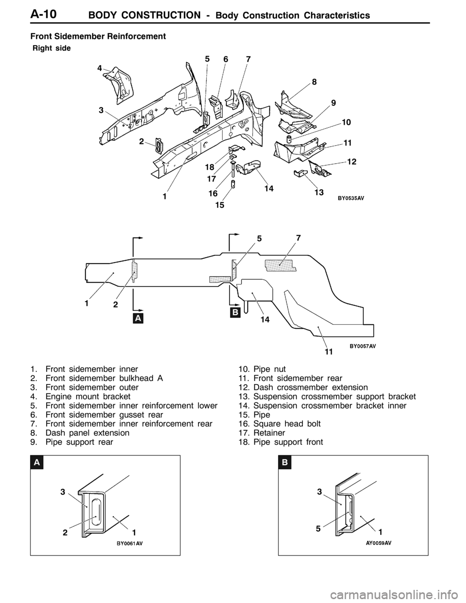
Front Sidemember Reinforcement
Right side
57 2 3 45
67
8
9
10
11
AB 11512
11 14
1413
16 17 18
1
2
1. Front sidemember inner
2. Front sidemember bulkhead A
3. Front sidemember outer
4. Engine mount bracket
5. Front sidemember inner reinforcement lower
6. Front sidemember gusset rear
7. Front sidemember inner reinforcement rear
8. Dash panel extension
9. Pipe support rear10. Pipe nut
11. Front sidemember rear
12. Dash crossmember extension
13. Suspension crossmember support bracket
14. Suspension crossmember bracket inner
15. Pipe
16. Square head bolt
17. Retainer
18. Pipe support front
Page 13 of 1449
BODY CONSTRUCTION -Body Construction Characteristics
A
713
12
B
11
712
A-11
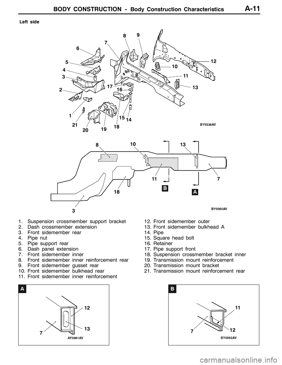
Left side
23
7 8 456789
10
11
AB
310
1112
13
14 15 16 17
18
19
20 21 1
13
18
1. Suspension crossmember support bracket
2. Dash crossmember extension
3. Front sidemember rear
4. Pipe nut
5. Pipe support rear
6. Dash panel extension
7. Front sidemember inner
8. Front sidemember inner reinforcement rear
9. Front sidemember gusset rear
10. Front sidemember bulkhead rear
11. Front sidemember inner reinforcement12. Front sidemember outer
13. Front sidemember bulkhead A
14. Pipe
15. Square head bolt
16. Retainer
17. Pipe support front
18. Suspension crossmember bracket inner
19. Transmission mount reinforcement
20. Transmission mount bracket
21. Transmission mount reinforcement rear
Page 14 of 1449

BODY CONSTRUCTION -Body Construction CharacteristicsBODY CONSTRUCTION -Body Construction CharacteristicsA-12
Front Deck
Strut house gussetandupper frame to front pillar brace have been added to improve body rigidity.
7
1 24 56
8
9
310
11
12 13
14
15
16
1. Strut tower bar bracket
2. Cowl top lower panel
3. Cowl top upper bracket center
4. Cowl top upper reinforcement center
5. Cowl top upper bracket side (LHD)
6. Cowl top inner panel
7. Cowl top upper panel
8. Pedal support bracket9. Clutch pedal support bracket
10. A/C Unit bracket (RHD)
11. Upper frame extension outer
12. Upper frame to front pillar brace
13. Cowl top upper reinforcement
14. Cowl top lower bracket
15. Upper frame extension inner
16. Strut house gusset
Dash Panel
1. A dash panel crossmember has been added and the thickness of the dash panel lower has been
increased to improve collision stability.
2. A silencer (steel sheet binding type vibration damping material) has been added between the dash
panel and dash panel silencer to control the penetrating sound and vibration from the engine.
18 3
76 5 4
2
1. Dash panel crossmember
2. Dash panel
3. Dash silencer center
4. Dash panel silencer5. Accel pedal reinforcement (LHD)
6. Dash panel reinforcement
7. Dash lower reinforcement (LHD)
8. Dash panel lower
Page 89 of 1449

HOW TO READ THE WIRING DIAGRAMS -How to Read Configuration DiagramsA-3
HOW TO READ CONFIGURATION DIAGRAMS
The wiring harness diagrams clearly show the connector locations and harness routings at each site
on actual vehicles.
Denotes connector No.
The same connector No. is used throughout the circuit diagrams to facilitate
connector location searches.
The first alphabetical symbol indicates the location site of the connector
and a number that follows is the unique number. Numbers are assigned to
parts in clockwise order on the diagram.
A-43
Example: A-12
Number specific to connector (serial number)
Connector location site symbol
A: Engine compartment
B: Engine and transmission
assembly
C: Dash panel
Denotes earth point.
Same earth number is used throughout circuit
diagrams to facilitate search of earth point. Refer
to SINGLE PART INSTALLATION POSITION -
EARTH MOUNTING LOCATIONS for details of
earth points.
Indicates the device to which the
connector is to be connected.
A-39 (2-B) Headlamp (LO: RH)
A-40 (1) Horn (LO)
A-41 (1) Horn (HI)
A-42 (2-B) Windshield washer motor
The number of connector pins and the
connector colour (except milk white)* are
shown for ease of retrieval.
Example: (2
-B)
Connector colour
(milk white if no colour is indicated)
Number of connector pins
*: Typical connector colours
B: Black
Y: Yellow
L: Blue
G: Green
R: Red
The markLshows the
standard mounting posi-
tion of wiring harness.
R
A-44
A-45
A-42
A-39
Denotes the colour of corrugated
tube or vinyl tube. (If not specified,
it is black.)
R: Red
Y: Yellow
Denotes a section covered by a
corrugated tube.
BR: Brown
V: Violet
O: Orange
GR: Gray
None: Milk whiteD: Floor and roof
E: Door
F: Luggage compartment
Page 99 of 1449

B-1
ELECTRICAL
WIRING
CONTENTS
WIRING HARNESS CONFIGURATION
DIAGRAMS 4.........................
OVERALL WIRING DIAGRAM
L.H. drive vehicles 4........................
R.H. drive vehicles 5........................
ENGINE COMPARTMENT
L.H. drive vehicles 6........................
R.H. drive vehicles 8........................
ENGINE AND TRANSMISSION
L.H. drive vehicles 10.......................
R.H. drive vehicles 14.......................
DASH PANEL
L.H. drive vehicles 18.......................
R.H. drive vehicles 24.......................
FLOOR AND ROOF
L.H. drive vehicles 30.......................
R.H. drive vehicles 32.......................
DOOR
L.H. drive vehicles 34.......................
R.H. drive vehicles 36.......................
LUGGAGE COMPARTMENT
L.H. drive vehicles 38.......................
R.H. drive vehicles 39.......................
SINGLE PART INSTALLATION
POSITION 40.........................
RELAY 40.................................
ECU 41...................................
SENSOR 43...............................
SOLENOID VALVE 46......................
INSPECTION CONNECTOR AND SPARE
CONNECTOR 47...........................
FUSIBLE LINK AND FUSE 48..............
EARTH CABLE 49.........................
EARTH 50.................................
CIRCUIT DIAGRAMS 54...............
J/B 54....................................
J/C
L.H. drive vehicles 56.......................
R.H. drive vehicles 62.......................
CENTRALIZED JUNCTION 68..............
POWER DISTRIBUTION SYSTEM 74........
STARTING SYSTEM 79....................
Page 116 of 1449
WIRING HARNESS CONFIGURATION DIAGRAMS
Connector
symbol
-01
thru
-45
C
C-29
C-05C-04C-03C-32C-02C-01
C-36
C-26
C-24
C-45
C-23C-22C-42C-41C-21
67
5
16
17
15
J/B
Y
B-18
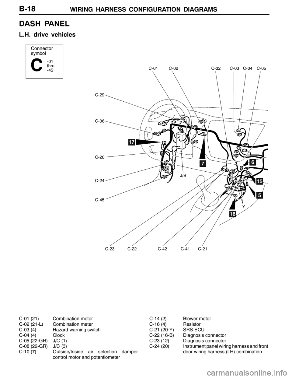
DASH PANEL
L.H. drive vehicles
C-01 (21) Combination meter
C-02 (21-L) Combination meter
C-03 (4) Hazard warning switch
C-04 (4) Clock
C-05 (22-GR) J/C (1)
C-08 (22-GR) J/C (3)
C-10 (7) Outside/Inside air selection damper
control motor and potentiometerC-14 (2) Blower motor
C-16 (4) Resistor
C-21 (20-Y) SRS-ECU
C-22 (16-B) Diagnosis connector
C-23 (12) Diagnosis connector
C-24 (20) Instrument panel wiring harness and front
door wiring harness (LH) combination
Page 122 of 1449
WIRING HARNESS CONFIGURATION DIAGRAMS
Connector
symbol
-01
thru
-46
C
C-46
C-24
C-04C-32C-03C-05C-28C-10
C-14C-16C-44C-43C-35C-41C-21
15
16
17
3
56Y
Y
B-24
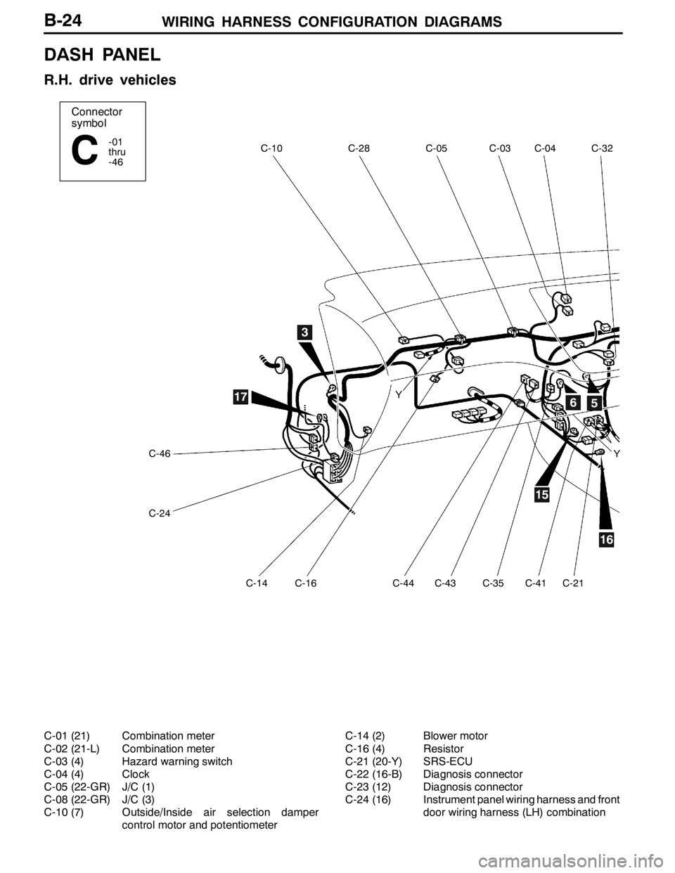
DASH PANEL
R.H. drive vehicles
C-01 (21) Combination meter
C-02 (21-L) Combination meter
C-03 (4) Hazard warning switch
C-04 (4) Clock
C-05 (22-GR) J/C (1)
C-08 (22-GR) J/C (3)
C-10 (7) Outside/Inside air selection damper
control motor and potentiometerC-14 (2) Blower motor
C-16 (4) Resistor
C-21 (20-Y) SRS-ECU
C-22 (16-B) Diagnosis connector
C-23 (12) Diagnosis connector
C-24 (16) Instrument panel wiring harness and front
door wiring harness (LH) combination