2007 MITSUBISHI LANCER EVOLUTION rear
[x] Cancel search: rearPage 1375 of 1449
SWS -Troubleshooting54B-11
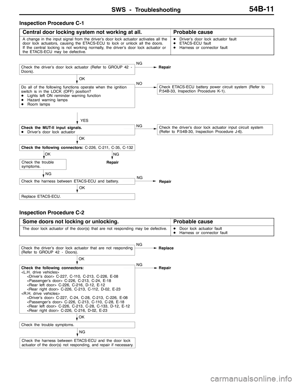
Inspection Procedure C-1
Central door locking system not working at all.
Probable cause
A change in the input signal from the driver’s door lock actuator activates all the
door lock actuators, causing the ETACS-ECU to lock or unlock all the doors.
If the central locking is not working normally, the driver’s door lock actuator or
the ETACS-ECU may be defective.DDriver’s door lock actuator fault
DETACS-ECU fault
DHarness or connector fault
NG
Repair
OK
Replace ETACS-ECU.
NG
Check the harness between ETACS-ECU and battery.NG
Repair
OK
Check the trouble
symptoms.
OK
Check the following connectors:C-226, C-211, C-35, C-132
YES
Check the driver’s door lock actuator (Refer to GROUP 42 -
Doors).NG
Repair
Do all of the following functions operate when the ignition
switch is in the LOCK (OFF) position?
DLights left ON reminder warning function
DHazard warning lamps
DRoom lampsNOCheck ETACS-ECU battery power circuit system (Refer to
P.54B-33, Inspection Procedure K-1). OK
Check the MUT-II input signals.
DDriver’s door lock actuatorNGCheck the driver’s door lock actuator input circuit system
(Refer to P.54B-30, Inspection Procedure J-6).
Inspection Procedure C-2
Some doors not locking or unlocking.
Probable cause
The door lock actuator of the door(s) that are not responding may be defective.DDoor lock actuator fault
DHarness or connector fault
NG
Check the harness between ETACS-ECU and the door lock
actuator of the door(s) not responding, and repair if necessary.
OK
Check the trouble symptoms.
OK
Check the following connectors:
Repair
Check the driver’s door lock actuator that are not responding
(Refer to GROUP 42 - Doors).NG
Replace
Page 1378 of 1449
SWS -Troubleshooting54B-14
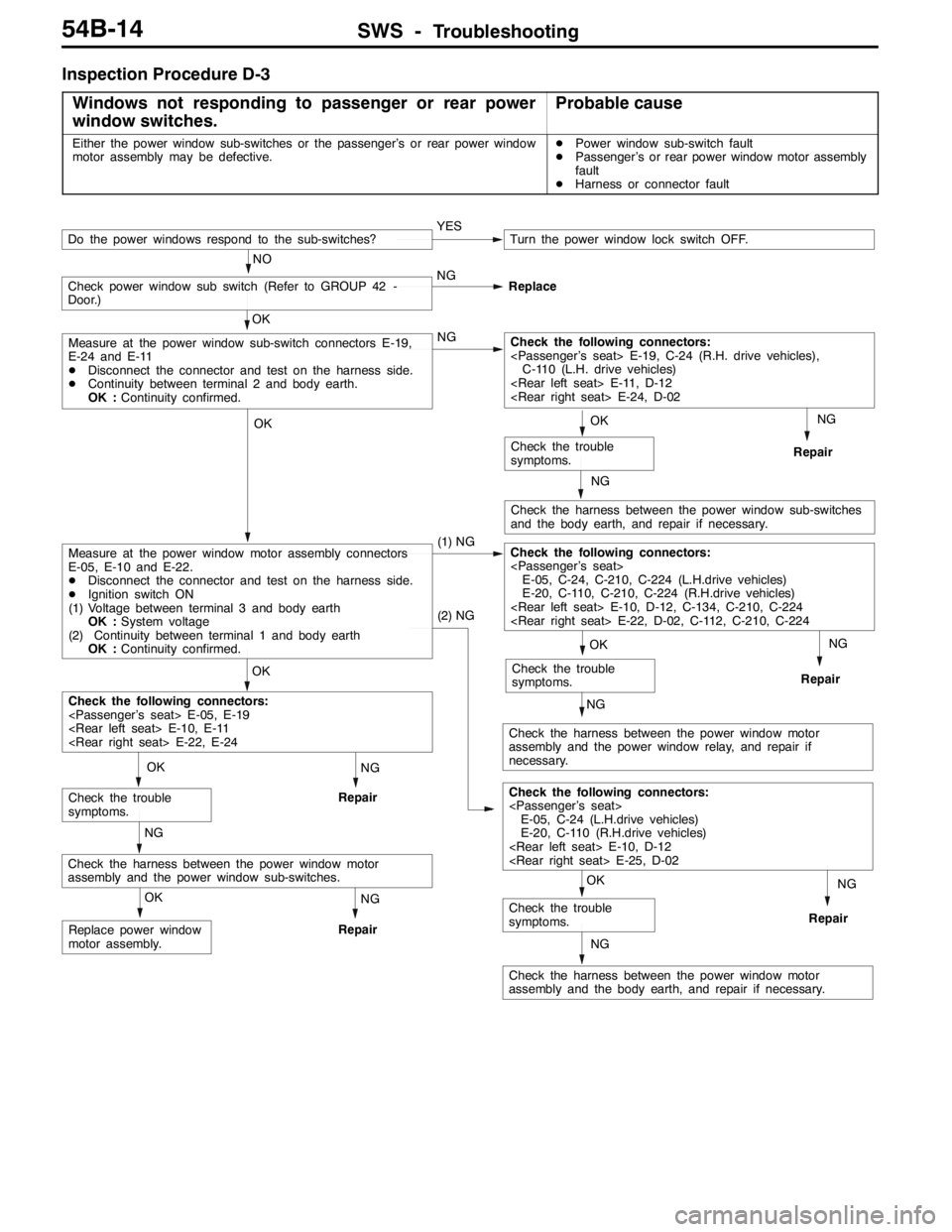
Inspection Procedure D-3
Windows not responding to passenger or rear power
window switches.
Probable cause
Either the power window sub-switches or the passenger’s or rear power window
motor assembly may be defective.DPower window sub-switch fault
DPassenger’s or rear power window motor assembly
fault
DHarness or connector fault
NG
Repair
NG
Check the harness between the power window sub-switches
and the body earth, and repair if necessary.
NG
Repair
NG
Check the harness between the power window motor
assembly and the power window relay, and repair if
necessary.NG
Repair
NG
Check the harness between the power window motor
assembly and the body earth, and repair if necessary.
NG
Repair
OK
Replace power window
motor assembly.
NG
Repair
NG
Check the harness between the power window motor
assembly and the power window sub-switches.
OK
Check the trouble
symptoms.
OK
Check the trouble
symptoms.
(2) NG
Check the following connectors:
E-05, C-24 (L.H.drive vehicles)
E-20, C-110 (R.H.drive vehicles)
OK
Check the trouble
symptoms.
OK
Check the trouble
symptoms.
OK
Check the following connectors:
OK
Measure at the power window motor assembly connectors
E-05, E-10 and E-22.
DDisconnect the connector and test on the harness side.
DIgnition switch ON
(1) Voltage between terminal 3 and body earth
OK :System voltage
(2) Continuity between terminal 1 and body earth
OK :Continuity confirmed.(1) NGCheck the following connectors:
E-05, C-24, C-210, C-224 (L.H.drive vehicles)
E-20, C-110, C-210, C-224 (R.H.drive vehicles)
OK
Measure at the power window sub-switch connectors E-19,
E-24 and E-11
DDisconnect the connector and test on the harness side.
DContinuity between terminal 2 and body earth.
OK :Continuity confirmed.NGCheck the following connectors:
C-110 (L.H. drive vehicles)
Check power window sub switch (Refer to GROUP 42 -
Door.)NG
Replace
YESTurn the power window lock switch OFF.
NO
Do the power windows respond to the sub-switches?
Page 1379 of 1449
SWS -Troubleshooting54B-15
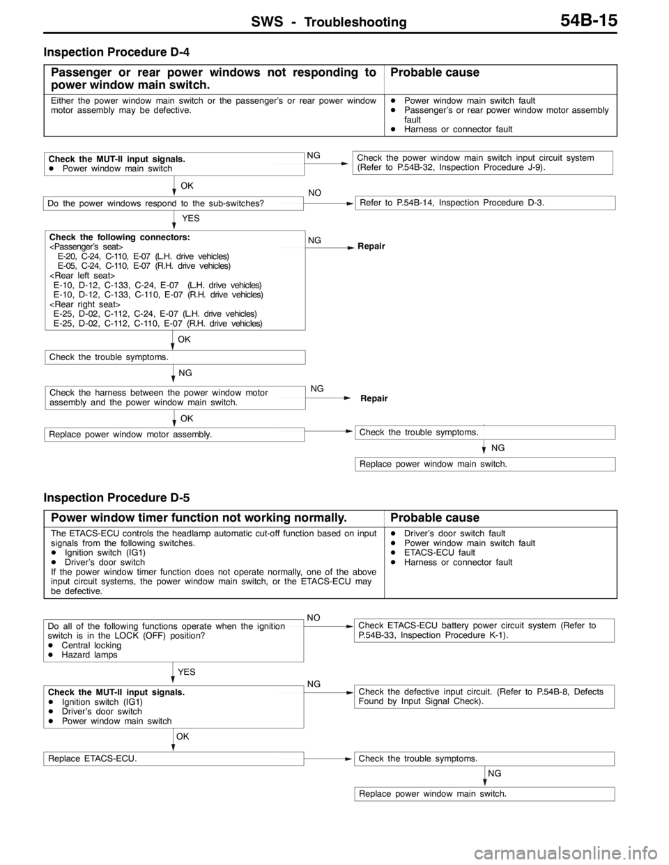
Inspection Procedure D-4
Passenger or rear power windows not responding to
power window main switch.
Probable cause
Either the power window main switch or the passenger’s or rear power window
motor assembly may be defective.DPower window main switch fault
DPassenger’s or rear power window motor assembly
fault
DHarness or connector fault
NG
Replace power window main switch.
OK
Replace power window motor assembly.Check the trouble symptoms.
NGCheck the harness between the power window motor
assembly and the power window main switch.NG
Repair
OK
Check the trouble symptoms.
YES
Check the following connectors:
E-20, C-24, C-110, E-07 (L.H. drive vehicles)
E-05, C-24, C-110, E-07 (R.H. drive vehicles)
E-10, D-12, C-133, C-24, E-07 (L.H. drive vehicles)
E-10, D-12, C-133, C-110, E-07 (R.H. drive vehicles)
E-25, D-02, C-112, C-24, E-07 (L.H. drive vehicles)
E-25, D-02, C-112, C-110, E-07 (R.H. drive vehicles)NG
Repair
OK
Do the power windows respond to the sub-switches?NORefer to P.54B-14, Inspection Procedure D-3.
Check the MUT-II input signals.
DPower window main switchNGCheck the power window main switch input circuit system
(Refer to P.54B-32, Inspection Procedure J-9).
Inspection Procedure D-5
Power window timer function not working normally.
Probable cause
The ETACS-ECU controls the headlamp automatic cut-off function based on input
signals from the following switches.
DIgnition switch (IG1)
DDriver’s door switch
If the power window timer function does not operate normally, one of the above
input circuit systems, the power window main switch, or the ETACS-ECU may
be defective.DDriver’s door switch fault
DPower window main switch fault
DETACS-ECU fault
DHarness or connector fault
NG
Replace power window main switch.
OK
Replace ETACS-ECU.Check the trouble symptoms.
Check the MUT-II input signals.
DIgnition switch (IG1)
DDriver’s door switch
DPower window main switchNGCheck the defective input circuit. (Refer to P.54B-8, Defects
Found by Input Signal Check).
Do all of the following functions operate when the ignition
switch is in the LOCK (OFF) position?
DCentral locking
DHazard lampsNOCheck ETACS-ECU battery power circuit system (Refer to
P.54B-33, Inspection Procedure K-1).
YES
Page 1387 of 1449
SWS -Troubleshooting54B-23
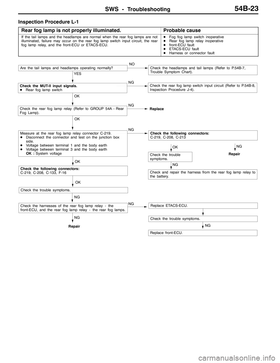
Inspection Procedure L-1
Rear fog lamp is not properly illuminated.
Probable cause
If the tail lamps and the headlamps are normal when the rear fog lamps are not
illuminated, failure may occur on the rear fog lamp switch input circuit, the rear
fog lamp relay, and the front-ECU or ETACS-ECU.DFog fog lamp switch inoperative
DRear fog lamp relay inoperative
Dfront-ECU fault
DETACS-ECU fault
DHarness or connector fault
Check the trouble symptoms.
NG
Repair
OK
Check the trouble symptoms.
YES
NG
Check the rear fog lamp switch input circuit (Refer to P.54B-8,
Inspection Procedure J-4).
Are the tail lamps and headlamps operating normally?NOCheck the headlamps and tail lamps (Refer to P.54B-7,
Trouble Symptom Chart).
OK
NG
Check the MUT-II input signals.
DRear fog lamp switch
Replace
OK
Check the rear fog lamp relay (Refer to GROUP 54A – Rear
Fog Lamp).
NGCheck the following connectors:
C-219, C-208, C-213
NG
Check and repair the harness from the rear fog lamp relay to
the battery.
OK
Check the trouble
symptoms.
Check the following connectors:
C-219, C-208, C-133, F-16
OK
Measure at the rear fog lamp relay connector C-219.
DDisconnect the connector and test on the junction box
side.
DVoltage between terminal 1 and the body earth
DVoltage between terminal 3 and the body earth
OK :System voltage
Replace ETACS-ECU.
NG
Replace front-ECU.
NG
RepairNG
NGCheck the harnesses of the rear fog lamp relay - the
front-ECU, and the rear fog lamp relay - the rear fog lamps.
Page 1389 of 1449
SWS -Troubleshooting54B-25
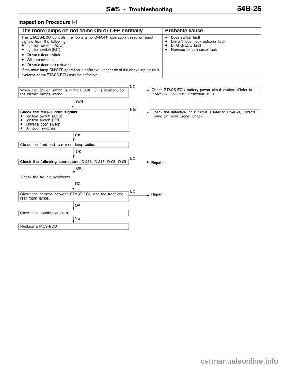
Inspection Procedure I-1
The room lamps do not come ON or OFF normally.
Probable cause
The ETACS-ECU controls the room lamp ON/OFF operation based on input
signals from the following.
DIgnition switch (ACC)
DIgnition switch (IG1)
DDriver’s door switchDDoor switch fault
DDriver’s door lock actuator fault
DETACS-ECU fault
DHarness or connector fault
DDriversdoorswitch
DAll door switches
DDriver’s door lock actuator
If the room lamp ON/OFF operation is defective, either one of the above input circuit
systems or the ETACS-ECU may be defective.
NGCheck the defective input circuit. (Refer to P.54B-8, Defects
Found by Input Signal Check).
OK
OK
NG
Check the trouble symptoms.
NG
RepairCheck the following connectors:C-226, C-218, D-03, D-05
NG
Repair
When the ignition switch is in the LOCK (OFF) position, do
the hazard lamps work?NOCheck ETACS-ECU battery power circuit system (Refer to
P.54B-33, Inspection Procedure K-1).
YES
Check the front and rear room lamp bulbs.
OK
Check the MUT-II input signals.
DIgnition switch (ACC)
DIgnition switch (IG1)
DDriver’s door switch
DAll door switches
NG
Replace ETACS-ECU.
OK
Check the trouble symptoms.
Check the harness between ETACS-ECU and the front and
rear room lamps.
Page 1392 of 1449
SWS -Troubleshooting54B-28
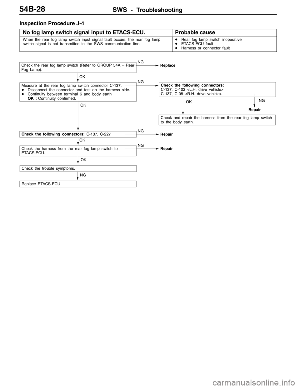
Inspection Procedure J-4
No fog lamp switch signal input to ETACS-ECU.
Probable cause
When the rear fog lamp switch input signal fault occurs, the rear fog lamp
switch signal is not transmitted to the SWS communication line.DRear fog lamp switch inoperative
DETACS-ECU fault
DHarness or connector fault
NG
RepairOK
Check and repair the harness from the rear fog lamp switch
to the body earth.
NG
Replace ETACS-ECU.
OK
OK
Check the harness from the rear fog lamp switch to
ETACS-ECU.NG
Repair
OK
Check the following connectors:C-137, C-227NG
Repair
OK
Measure at the rear fog lamp switch connector C-137.
DDisconnect the connector and test on the harness side.
DContinuity between terminal 6 and body earth
OK :Continuity confirmed.NGCheck the following connectors:
C-137, C-102
C-137, C-08
Check the rear fog lamp switch (Refer to GROUP 54A - Rear
Fog Lamp).NG
Replace
Check the trouble symptoms.
Page 1393 of 1449
SWS -Troubleshooting54B-29
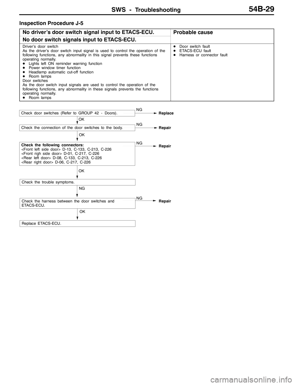
Inspection Procedure J-5
No driver’s door switch signal input to ETACS-ECU.
Probable cause
No door switch signals input to ETACS-ECU.
Driver’s door switch
As the driver’s door switch input signal is used to control the operation of the
following functions, any abnormality in this signal prevents these functions
operating normally.
DLights left ON reminder warning function
DPower window timer function
DHeadlamp automatic cut-off function
DRoom lamps
Door switches
As the door switch input signals are used to control the operation of the
following functions, any abnormality in these signals prevents the functions
operating normally.
DRoom lampsDDoor switch fault
DETACS-ECU fault
DHarness or connector fault
OK
Replace ETACS-ECU.
NG
Check the harness between the door switches and
ETACS-ECU.NG
Repair
OK
Check the trouble symptoms.
OK
Check the following connectors:
Repair
OK
Check the connection of the door switches to the body.NG
Repair
Check door switches (Refer to GROUP 42 - Doors).NG
Replace
Page 1398 of 1449

SWS -Troubleshooting54B-34
CHECKS AT ECU TERMINALS
ETACS-ECU
*
Y0795AU
NOTE
*See the list below for data on the ETACS-ECU terminal 1 - 20 connectors. As the ETACS-ECU connects
directly onto the junction box, the voltages cannot be measured.
Terminal
No.Check itemsChecking requirementsNormal condition
1Power window relay outputWhen power windows operating
normallySystem voltage
2Battery power supply (for central
locking)Any timeSystem voltage
3Earth (for ECU)Any time0V
4Ignition switch (ACC)Ignition switch: ACCSystem voltage
5Room lamp outputWhen room lamps ON2 V or below
6---
7Door switch inputWhen any one door switch ON (door
open)0V
8Ignition switch (IG1) power supplyIgnition switch: ONSystem voltage
9Right-hand turn signal lamp outputWhen right-hand turn signal lamp ONSystem voltage
10Driver’s door switch inputWhen driver’s door switch ON (door
open)0V
11Battery power supply (for hazard
lamps)Any timeSystem voltage
12Central locking (lock) outputWhen door lock actuator operating
(locking operation)System voltage
13Central locking (unlock) output (NOT
driver’s door)When door lock actuator operating
(unlocking)System voltage
14Left-hand turn signal lamp outputWhen left-hand turn signal lamp ONSystem voltage
15 - 17---
18Ignition switch (ACC) power supplyIgnition switch: ACCSystem voltage
19Battery power supply for interior lampWhen interior lamp ONSystem voltage
20Battery power supply (for ECU)Any timeSystem voltage
21Rear fog lamp switch inputWhen the rear fog lamp switch ON0V
22Central locking (unlock) output (for
driver’s door)When door lock actuator operating
(unlocking)System voltage
23---
24 - 32---
33Door lock key cylinder switch input
(unlock switch)When driver’s door lock unlocked0V
34Door lock key cylinder switch input
(lock switch)When driver’s door lock locked0V