Page 1028 of 1449
FRONT SUSPENSION -General Information33A-2
GENERAL INFORMATION
The front suspension is a McPherson strut with
coil spring. The shock absorber is gas-filled
hydraulic double-acting type.
COIL SPRING
ItemRS ,
RS-IIRS
Wire diameter�·average
diameter�·free length mm14�·155�·28114�·155�·275
CONSTRUCTION DIAGRAM
Stabilizer barCoil spring
Strut assembly
(shock absorber) Crossmember
Lower armStrut insulator
Stabilizer link
Crossmember bar
Lower arm bushing
(pillow ball bushing with rubber)
Page 1072 of 1449

ABS <4WD> -General Information35B-2
GENERAL INFORMATION
ABS has been adopted as optional equipment in
RS-IIto maintain directional stability and steering
performance during sudden braking or braking on
slippery road surfaces.
The ABS control method is a 4-sensor, 4-channel
method which provides independent control for all
wheels.
Following system for Lancer EVOLUTION-VII has
been modified from Lancer EVOLUTION-VI Tommi
Makinen Edition.DBy adding lateral G sensor, longitudinal G
sensor and steering wheel sensor, optimized
ABS control at the time of cornering.
DBy inputting parking brake switch signal to
ABS-ECU with pulling parking brake lever, ABS
control has been optimized.
DABS-ECU outputs ABS signal to 4WD-ECU.
DG sensor (lateral), steering wheel sensor and
parking brake switch have been added to the
diagnosis and service data.
DABS-ECU connector has been changed.
EBD CONTROL
In ABS, electronic control method is used by which
the rear wheel brake hydraulic pressure during
braking is regulated by rear wheel control solenoid
valves in accordance with the vehicle’s rate of
deceleration and the front and rear wheel slippage
which are calculated from the each wheel speed
sensor’s signal. EBD control is a control system
which provides a high level of control for both vehicle
braking force and vehicle stability. The system has
the following features:
DBecause the system provides the optimum rear
wheel braking force regardless of the vehicleladen condition and the condition of the road
surface, the system reduces the required pedal
depression force, particularly when the vehicle
is heavily laden or driving on road surfaces
with high frictional coefficients.
DBecause the duty placed on the front brakes
has been reduced, the increases in pad
temperature can be controlled to improve the
wear resistance characteristics of the pad,
during front brakes applying.
DControl valves such as the proportioning valve
are no longer required.
SPECIFICATIONS
ItemSpecifications
ABS control method4-sensor, 4-channel
No. of ABS rotor teethFront43
Rear43
ABS speed sensorTypeMagnet coil typep
Gap between sensor and rotor mm0.85 / 0.60 (non-adjustable type)
Page 1116 of 1449

STEERING -General Information37A-2
GENERAL INFORMATION
The system has been equipped with the MOMO
leather 3-spoke-type steering wheel with built-in
SRS airbag.
The steering column is equipped with tilt steering
mechanism.
The power steering is an integral rack and piniontype that combines the steering gear and linkage
into one light-weight and compact assembly.
The steering system uses a vane oil pump with
a fluid flow control system, so that steering effort
varies with engine speed.
ItemLancer EVOLUTION-
Steering wheelTypeMOMO 3-spoke typeg
Outside diameter mm380 ,
365
Maximum number of turns2.1
Steering columnColumn mechanismTilt steering
Power steering typeIntegral type
Oil pumpTypeVariable capacity type (vane pump)pp
Basic discharge amount cm3/rev.9.6
Relief pressure MPa8.3 - 9.0
Reservoir typeSeparate type
Pressure switchEquipped
Steering gear and linkageTypeRack and pinionggg
Stroke ratio (Rack stroke/Steering wheel
Maximum turning radius)68.61
Rack stroke mm146
Steering angleInner wheel32°gg
Outer wheel (for reference)27°
Power steering fluidSpecified lubricantsAutomatic transmission fluid DEXRON IIg
Quantity LApproximately 1.0
Page 1120 of 1449
STEERING -Special Tools37A-6
Tool UseName Number
MB991197Bar (long type)DPress fitting of rack housing bearing
DTo press in the oil seal for the rack
MB991214Rack installerRack installation
MB990925Bearing and oil
seal installer setInstallation of the oil seal and bearing
(Refer to GROUP 26 - Special Tools.)
MB991120Needle bearing
pullerRemoval of rack housing needle bearing
MB991203Oil seal and
bearing installerTo press in the valve housing oil seal and
bearing
MB991317Seal ring installerCompression of the seal rings after
replacement of the pinion seal rings
MB990941Torque tube
bearing installerInstallation of valve housing oil seal
MB991561Boot band crimp-
ing toolInstallation of bellows band
MB990776Front axle baseInstallation of dust cover for tie rod end ball joint
Page 1441 of 1449

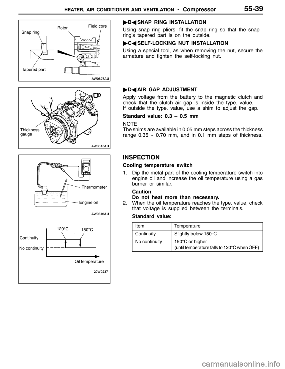
HEATER, AIR CONDITIONER AND VENTILATION-Compressor55-39
"BASNAP RING INSTALLATION
Using snap ring pliers, fit the snap ring so that the snap
ring’s tapered part is on the outside.
"CASELF-LOCKING NUT INSTALLATION
Using a special tool, as when removing the nut, secure the
armature and tighten the self-locking nut.
"DAAIR GAP ADJUSTMENT
Apply voltage from the battery to the magnetic clutch and
check that the clutch air gap is inside the type. value.
If outside the type. value, use a shim to adjust the gap.
Standard value: 0.3 – 0.5 mm
NOTE
The shims are available in 0.05 mm steps across the thickness
range 0.35 - 0.70 mm, and in 0.1 mm steps of thickness.
INSPECTION
Cooling temperature switch
1. Dip the metal part of the cooling temperature switch into
engine oil and increase the oil temperature using a gas
burner or similar.
Caution
Do not heat more than necessary.
2. When the oil temperature reaches the type. value, check
that voltage is supplied between the terminals.
Standard value:
ItemTemperature
ContinuitySlightly below 150°C
No continuity150°C or higher
(until temperature falls to 120°C when OFF)
Snap ringRotorField core
Tapered part
Thickness
gauge
Thermometer
Engine oil
Continuity
No continuity
Oil temperature
120°C150°C
Page:
< prev 1-8 9-16 17-24