Page 1155 of 1449
BODY -Fuel Filler Door42-7
FUEL FILLER DOOR
REMOVAL AND INSTALLATION
Pre-removal and Post-installation Operations
DRear Seat Removal and Installation. (Refer to GROUP
52A.)
DFront Scuff Plate (Driver’s Side), Rear Scuff Plate(Driver’s Side), Center Pillar Lower Trim (Driver’s
Side), Quarter Trim (Driver’s Side) Removal and
Installation (Refer to GROUP 52A – Trim.)
5
1
3 4 3
2
5.0±1.0 N·m
Adjustment of clearance around
fuel filler door
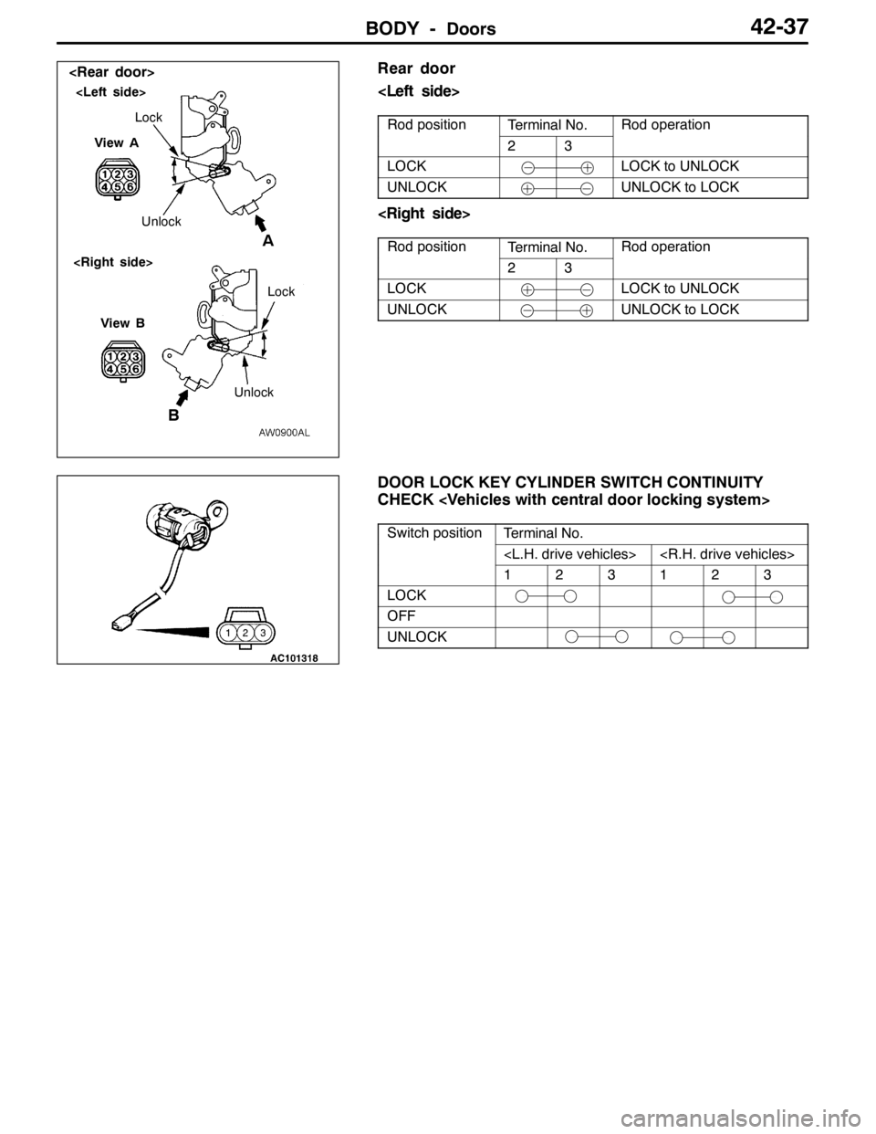
Removal steps
1. Fuel filler door panel assembly
2. Clip
3. Fuel filler door hook assembly4. Fuel filler door lock release cable
5. Fuel filler door lock release handle
Page 1168 of 1449
BODY -DoorsBODY -Doors42-20
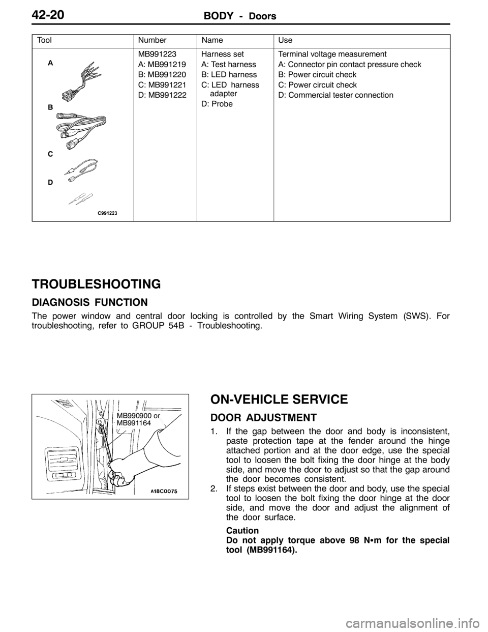
Tool UseName Number
A
B
C
D
MB991223
A: MB991219
B: MB991220
C: MB991221
D: MB991222Harness set
A: Test harness
B: LED harness
C: LED harness
adapter
D: ProbeTerminal voltage measurement
A: Connector pin contact pressure check
B: Power circuit check
C: Power circuit check
D: Commercial tester connection
TROUBLESHOOTING
DIAGNOSIS FUNCTION
The power window and central door locking is controlled by the Smart Wiring System (SWS). For
troubleshooting, refer to GROUP 54B - Troubleshooting.
ON-VEHICLE SERVICE
DOOR ADJUSTMENT
1. If the gap between the door and body is inconsistent,
paste protection tape at the fender around the hinge
attached portion and at the door edge, use the special
tool to loosen the bolt fixing the door hinge at the body
side, and move the door to adjust so that the gap around
the door becomes consistent.
2. If steps exist between the door and body, use the special
tool to loosen the bolt fixing the door hinge at the door
side, and move the door and adjust the alignment of
the door surface.
Caution
Do not apply torque above 98 NSm for the special
tool (MB991164).
MB990900 or
MB991164
Page 1184 of 1449
BODY -DoorsBODY -Doors42-36
"BALOWER SASH INSTALLATION
Be sure to install the lower sash to the window rear sash
(at door) securely.
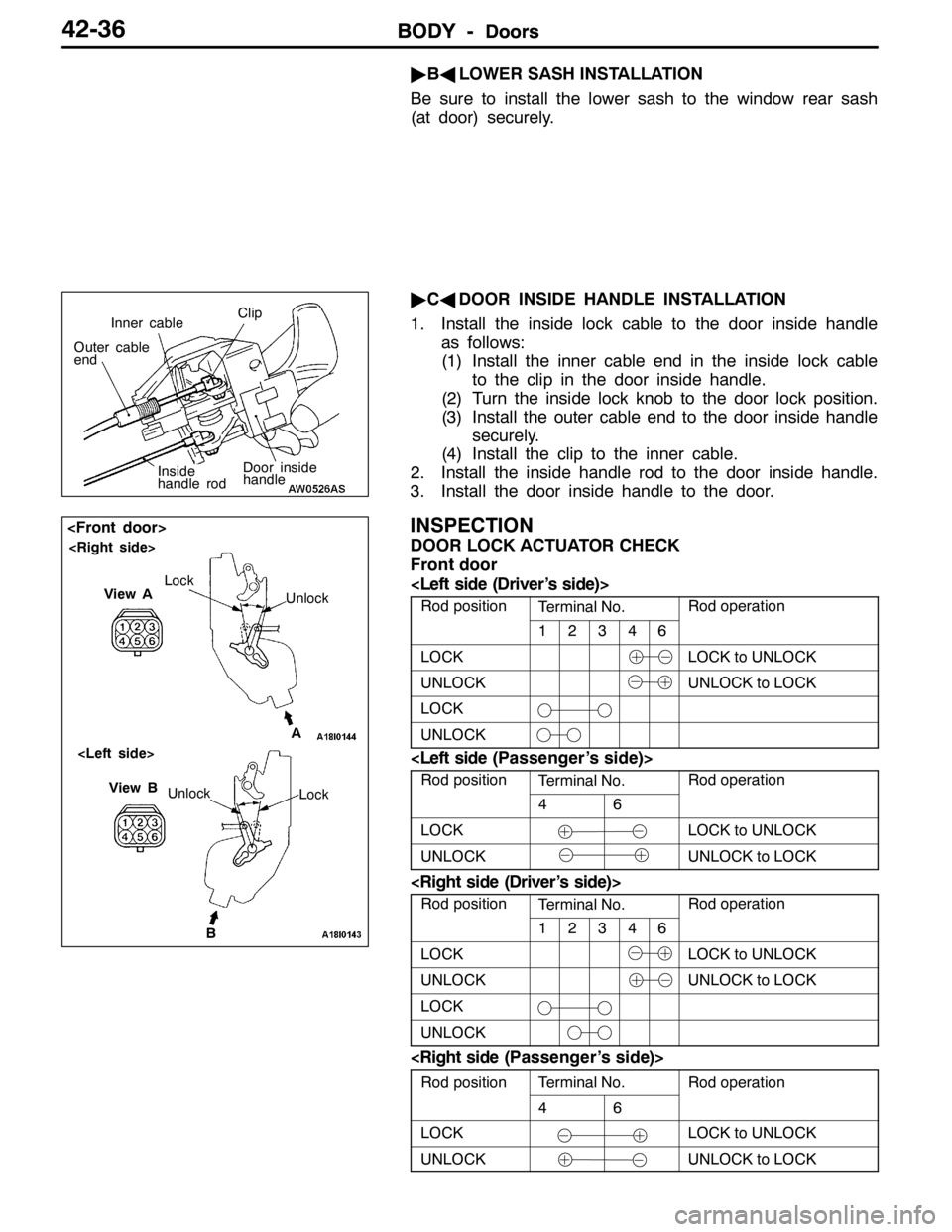
"CADOOR INSIDE HANDLE INSTALLATION
1. Install the inside lock cable to the door inside handle
as follows:
(1) Install the inner cable end in the inside lock cable
to the clip in the door inside handle.
(2) Turn the inside lock knob to the door lock position.
(3) Install the outer cable end to the door inside handle
securely.
(4) Install the clip to the inner cable.
2. Install the inside handle rod to the door inside handle.
3. Install the door inside handle to the door.
INSPECTION
DOOR LOCK ACTUATOR CHECK
Front door
Rod positionTerminal No.Rod operation
12346
LOCKLOCK to UNLOCK
UNLOCKUNLOCK to LOCK
LOCK
UNLOCK
Rod positionTerminal No.Rod operation
46
LOCKLOCK to UNLOCK
UNLOCKUNLOCK to LOCK
Rod positionTerminal No.Rod operation
12346
LOCKLOCK to UNLOCK
UNLOCKUNLOCK to LOCK
LOCK
UNLOCK
Rod positionTerminal No.Rod operationp
46
p
LOCKLOCK to UNLOCK
UNLOCKUNLOCK to LOCK
Door inside
handle
Inner cableClip
Outer cable
end
Inside
handle rod
B Unlock
View B
Lock
View A
Unlock Lock
A
Page 1185 of 1449
BODY -Doors42-37
Rear door
Rod positionTerminal No.Rod operationp
23
p
LOCKLOCK to UNLOCK
UNLOCKUNLOCK to LOCK
Rod positionTerminal No.Rod operationp
23
p
LOCKLOCK to UNLOCK
UNLOCKUNLOCK to LOCK
DOOR LOCK KEY CYLINDER SWITCH CONTINUITY
CHECK
Switch positionTerminal No.p
123123
LOCK
OFF
UNLOCK
BA
View ALock
Unlock
View B
UnlockLock
Page 1309 of 1449
SRS -AirBagModuleandSeatBeltPre-tensioner
Disposal Procedures52B-65
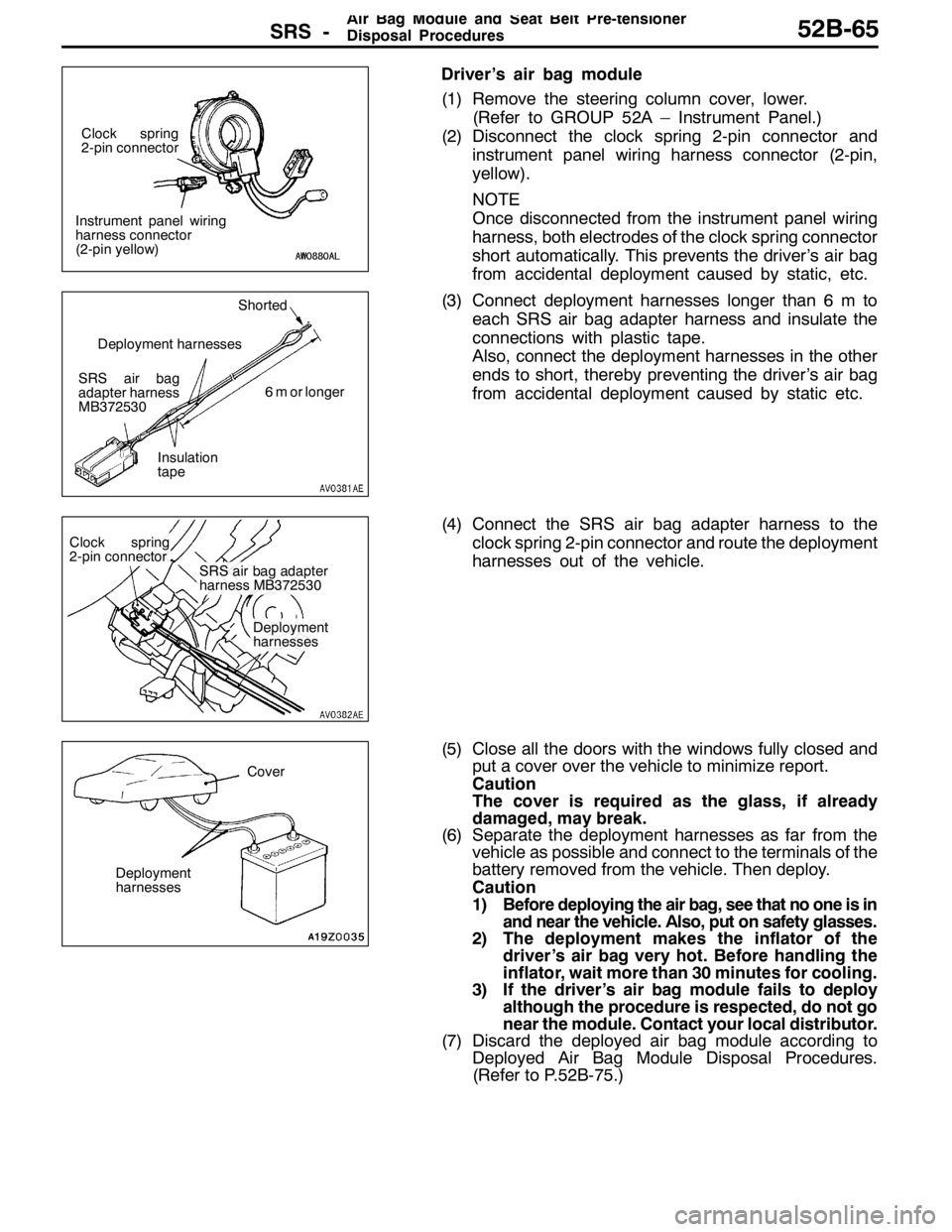
Driver’s air bag module
(1) Remove the steering column cover, lower.
(Refer to GROUP 52A – Instrument Panel.)
(2) Disconnect the clock spring 2-pin connector and
instrument panel wiring harness connector (2-pin,
yellow).
NOTE
Once disconnected from the instrument panel wiring
harness, both electrodes of the clock spring connector
short automatically. This prevents the driver’s air bag
from accidental deployment caused by static, etc.
(3) Connect deployment harnesses longer than 6 m to
each SRS air bag adapter harness and insulate the
connections with plastic tape.
Also, connect the deployment harnesses in the other
ends to short, thereby preventing the driver’s air bag
from accidental deployment caused by static etc.
(4) Connect the SRS air bag adapter harness to the
clock spring 2-pin connector and route the deployment
harnesses out of the vehicle.
(5) Close all the doors with the windows fully closed and
put a cover over the vehicle to minimize report.
Caution
The cover is required as the glass, if already
damaged, may break.
(6) Separate the deployment harnesses as far from the
vehicle as possible and connect to the terminals of the
battery removed from the vehicle. Then deploy.
Caution
1) Before deploying the air bag, see that no one is in
and near the vehicle. Also, put on safety glasses.
2) The deployment makes the inflator of the
driver’s air bag very hot. Before handling the
inflator, wait more than 30 minutes for cooling.
3) If the driver’s air bag module fails to deploy
although the procedure is respected, do not go
near the module. Contact your local distributor.
(7) Discard the deployed air bag module according to
Deployed Air Bag Module Disposal Procedures.
(Refer to P.52B-75.)
Instrument panel wiring
harness connector
(2-pin yellow)Clock spring
2-pin connector
SRS air bag
adapter harness
MB372530Shorted
6 m or longer
Insulation
tape Deployment harnesses
Clock spring
2-pin connector
SRS air bag adapter
harness MB372530
Deployment
harnesses
Cover
Deployment
harnesses
Page 1367 of 1449
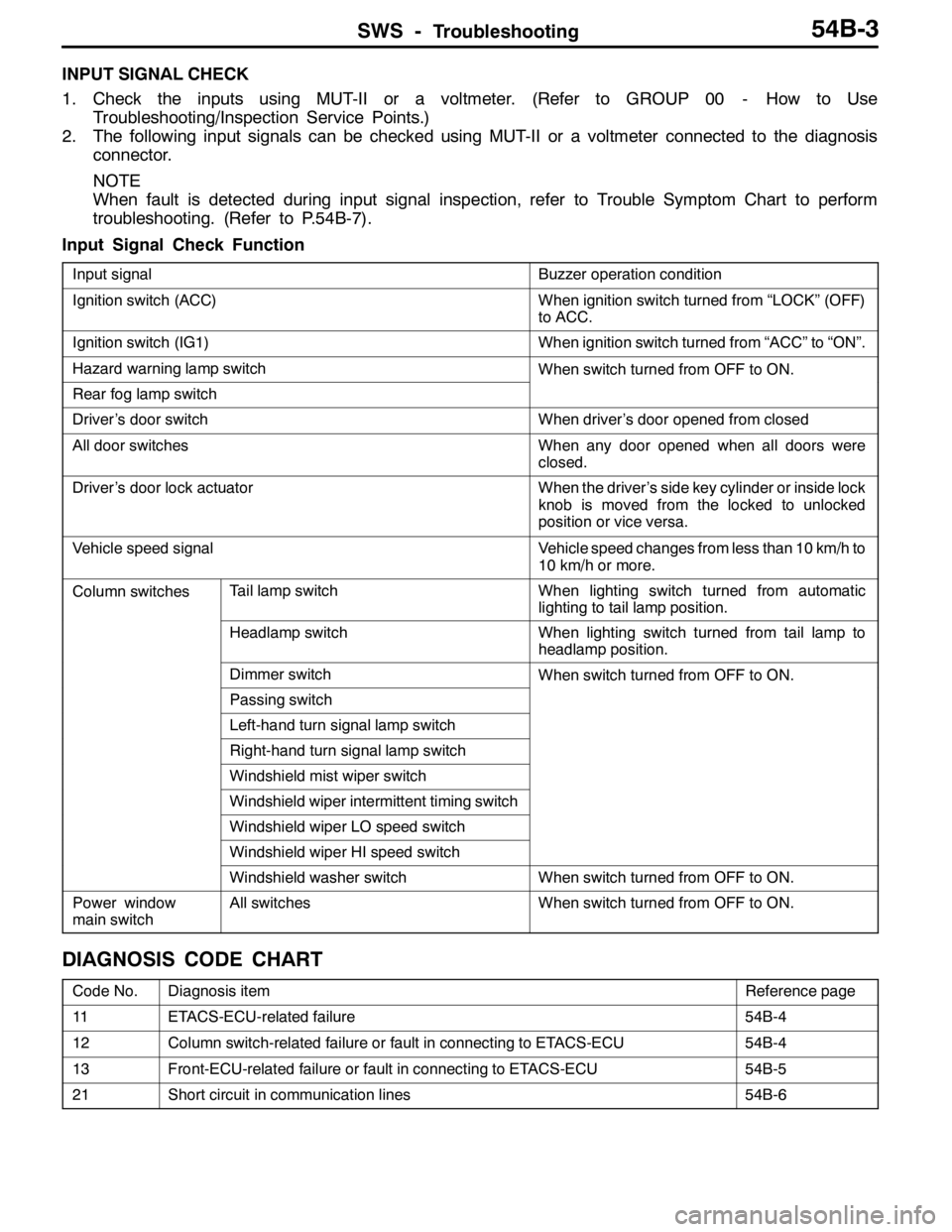
SWS -Troubleshooting54B-3
INPUT SIGNAL CHECK
1. Check the inputs using MUT-II or a voltmeter. (Refer to GROUP 00 - How to Use
Troubleshooting/Inspection Service Points.)
2. The following input signals can be checked using MUT-II or a voltmeter connected to the diagnosis
connector.
NOTE
When fault is detected during input signal inspection, refer to Trouble Symptom Chart to perform
troubleshooting. (Refer to P.54B-7).
Input Signal Check Function
Input signalBuzzer operation condition
Ignition switch (ACC)When ignition switch turned from “LOCK” (OFF)
to ACC.
Ignition switch (IG1)When ignition switch turned from “ACC” to “ON”.
Hazard warning lamp switchWhen switch turned from OFF to ON.
Rear fog lamp switch
Driver’s door switchWhen driver’s door opened from closed
All door switchesWhen any door opened when all doors were
closed.
Driver’s door lock actuatorWhen the driver’s side key cylinder or inside lock
knob is moved from the locked to unlocked
position or vice versa.
Vehicle speed signalVehicle speed changes from less than 10 km/h to
10 km/h or more.
Column switchesTail lamp switchWhen lighting switch turned from automatic
lighting to tail lamp position.
Headlamp switchWhen lighting switch turned from tail lamp to
headlamp position.
Dimmer switchWhen switch turned from OFF to ON.
Passing switch
Left-hand turn signal lamp switch
Right-hand turn signal lamp switch
Windshield mist wiper switch
Windshield wiper intermittent timing switch
Windshield wiper LO speed switch
Windshield wiper HI speed switch
Windshield washer switchWhen switch turned from OFF to ON.
Power window
main switchAll switchesWhen switch turned from OFF to ON.
DIAGNOSIS CODE CHART
Code No.Diagnosis itemReference page
11ETACS-ECU-related failure54B-4
12Column switch-related failure or fault in connecting to ETACS-ECU54B-4
13Front-ECU-related failure or fault in connecting to ETACS-ECU54B-5
21Short circuit in communication lines54B-6
Page 1371 of 1449
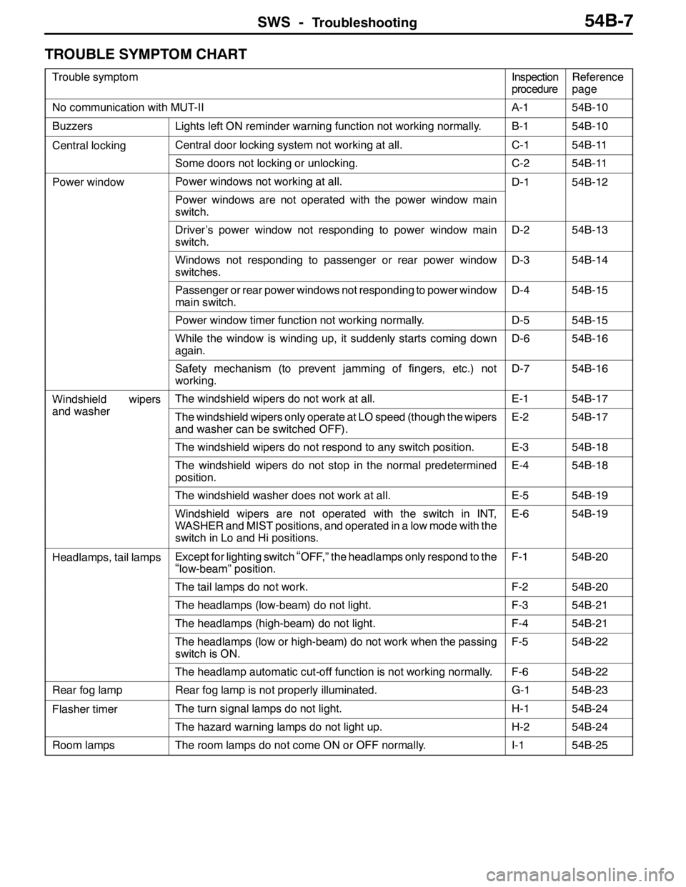
SWS -Troubleshooting54B-7
TROUBLE SYMPTOM CHART
Trouble symptomInspection
procedureReference
page
No communication with MUT-IIA-154B-10
BuzzersLights left ON reminder warning function not working normally.B-154B-10
Central lockingCentral door locking system not working at all.C-154B-11g
Some doors not locking or unlocking.C-254B-11
Power windowPower windows not working at all.D-154B-12
Power windows are not operated with the power window main
switch.
Driver’s power window not responding to power window main
switch.D-254B-13
Windows not responding to passenger or rear power window
switches.D-354B-14
Passenger or rear power windows not responding to power window
main switch.D-454B-15
Power window timer function not working normally.D-554B-15
While the window is winding up, it suddenly starts coming down
again.D-654B-16
Safety mechanism (to prevent jamming of fingers, etc.) not
working.D-754B-16
Windshield wipers
dh
The windshield wipers do not work at all.E-154B-17p
and washerThe windshield wipers only operate at LO speed (though the wipers
and washer can be switched OFF).E-254B-17
The windshield wipers do not respond to any switch position.E-354B-18
The windshield wipers do not stop in the normal predetermined
position.E-454B-18
The windshield washer does not work at all.E-554B-19
Windshield wipers are not operated with the switch in INT,
WASHER and MIST positions, and operated in a low mode with the
switch in Lo and Hi positions.E-654B-19
Headlamps, tail lampsExcept for lighting switch“OFF,” the headlamps only respond to the
“low-beam” position.
F-154B-20
The tail lamps do not work.F-254B-20
The headlamps (low-beam) do not light.F-354B-21
The headlamps (high-beam) do not light.F-454B-21
The headlamps (low or high-beam) do not work when the passing
switch is ON.F-554B-22
The headlamp automatic cut-off function is not working normally.F-654B-22
Rear fog lampRear fog lamp is not properly illuminated.G-154B-23
Flasher timerThe turn signal lamps do not light.H-154B-24
The hazard warning lamps do not light up.H-254B-24
Room lampsThe room lamps do not come ON or OFF normally.I-154B-25
Page 1372 of 1449
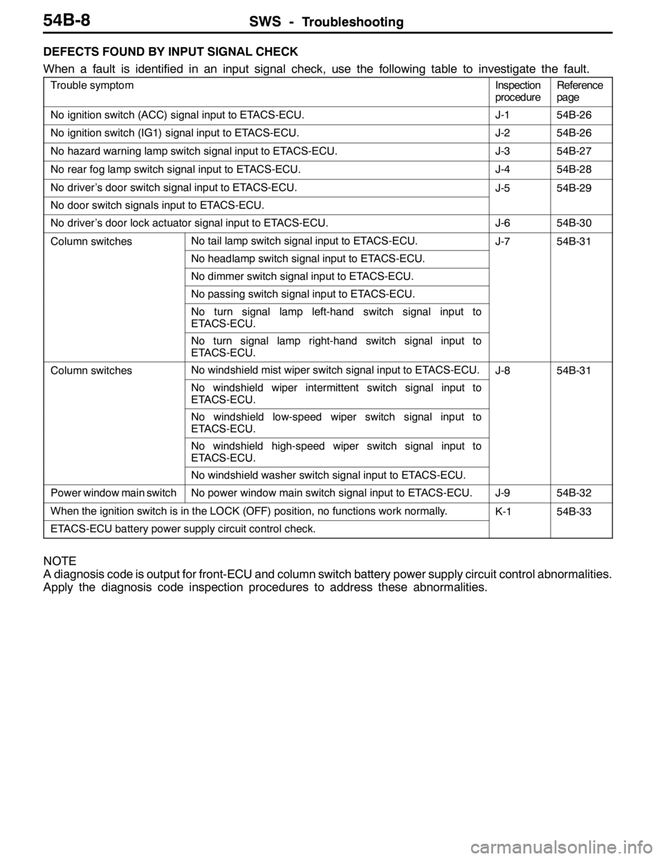
SWS -TroubleshootingSWS -Troubleshooting54B-8
DEFECTS FOUND BY INPUT SIGNAL CHECK
When a fault is identified in an input signal check, use the following table to investigate the fault.
Trouble symptomInspection
procedureReference
page
No ignition switch (ACC) signal input to ETACS-ECU.J-154B-26
No ignition switch (IG1) signal input to ETACS-ECU.J-254B-26
No hazard warning lamp switch signal input to ETACS-ECU.J-354B-27
No rear fog lamp switch signal input to ETACS-ECU.J-454B-28
No driver’s door switch signal input to ETACS-ECU.J-554B-29
No door switch signals input to ETACS-ECU.
No driver’s door lock actuator signal input to ETACS-ECU.J-654B-30
Column switchesNo tail lamp switch signal input to ETACS-ECU.J-754B-31
No headlamp switch signal input to ETACS-ECU.
No dimmer switch signal input to ETACS-ECU.
No passing switch signal input to ETACS-ECU.
No turn signal lamp left-hand switch signal input to
ETACS-ECU.
No turn signal lamp right-hand switch signal input to
ETACS-ECU.
Column switchesNo windshield mist wiper switch signal input to ETACS-ECU.J-854B-31
No windshield wiper intermittent switch signal input to
ETACS-ECU.
No windshield low-speed wiper switch signal input to
ETACS-ECU.
No windshield high-speed wiper switch signal input to
ETACS-ECU.
No windshield washer switch signal input to ETACS-ECU.
Power window main switchNo power window main switch signal input to ETACS-ECU.J-954B-32
When the ignition switch is in the LOCK (OFF) position, no functions work normally.K-154B-33
ETACS-ECU battery power supply circuit control check.
NOTE
A diagnosis code is output for front-ECU and column switch battery power supply circuit control abnormalities.
Apply the diagnosis code inspection procedures to address these abnormalities.