2007 MITSUBISHI LANCER EVOLUTION check oil
[x] Cancel search: check oilPage 968 of 1449

REAR AXLE -On-vehicle Service27B-22
8. If the measured value exceeds the standard value, replace
the hydraulic unit.
9. Connect the hydraulic unit and the hydraulic unit hose
assembly, and connect the torque transfer differential and
hydraulic unit hose assembly, tighten the flare nut in
specified torque.
Tightening torque: 34±5 N·m (Thread is not lubricated)
26±4 N·m (Thread is lubricated)
10. Supply the specified fluid up to the MAX level of the
oil reservoir, and bleed.
Specified fluid: ATF-SP III
Quantity: 1 L
WHEEL BEARING AXIAL PLAY CHECK
1. Remove the brake caliper and brake disc.
2. Check the bearing’s axial play.
Place a dial gauge against the hub surface; then move
the hub in the axial direction and check whether or not
there is axial play.
Limit: 0.05 mm
3. If the axial play exceeds the limit, the castle nut should
be tightened to the specified torque 225±25 N·m and
check the axial play again.
4. Replace the rear hub assembly if an adjustment cannot
be made to within the limit.
WHEEL BEARING ROTARY-SLIDING
RESISTANCE CHECK
1. Remove the brake caliper and brake disc.
2. After turning the hub a few times to seat the bearing,
wind a rope around the hub bolt and turn the hub by
pulling at a 90_angle with a spring balance. Measure
to determine whether or not the rotary-sliding resistance
of the rear hub is at the limit value.
Limit: 22 N or less
Page 969 of 1449

REAR AXLE -On-vehicle Service27B-23
3. If the limit value is exceeded, loosen the flange nut and
then tighten it to the specified torque 225±25 N·m and
check the rear hub rotary sliding resistance again.
4. Replace the rear hub assembly if an adjustment cannot
be made to within the limit.
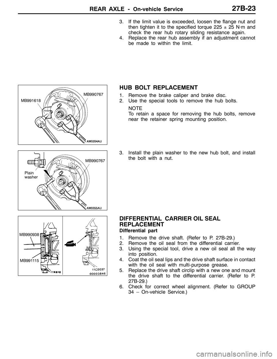
HUB BOLT REPLACEMENT
1. Remove the brake caliper and brake disc.
2. Use the special tools to remove the hub bolts.
NOTE
To retain a space for removing the hub bolts, remove
near the retainer spring mounting position.
3. Install the plain washer to the new hub bolt, and install
the bolt with a nut.
DIFFERENTIAL CARRIER OIL SEAL
REPLACEMENT
Differential part
1. Remove the drive shaft. (Refer to P. 27B-29.)
2. Remove the oil seal from the differential carrier.
3. Using the special tool, drive a new oil seal all the way
into position.
4. Coat the oil seal lips and the drive shaft surface in contact
with the oil seal with multi-purpose grease.
5. Replace the drive shaft circlip with a new one and mount
the drive shaft to the differential carrier. (Refer to P.
27B-29.)
6. Check for correct wheel alignment. (Refer to GROUP
34 – On-vehicle Service.)
MB991618MB990767
Plain
washerMB990767
MB990938
MB991115
Page 970 of 1449

REAR AXLE -On-vehicle Service27B-24
Torque transfer mechanism part
1. Remove the drive shaft. (Refer to P. 27B-29.)
2. Remove the oil seal from the differential carrier.
3. Using the special tool, drive a new oil seal all the way
into position.
4. Coat the oil seal lips and the drive shaft surface in contact
with the oil seal with the specified grease.
Specified grease: Vaseline
5. Replace the drive shaft circlip with a new one and mount
the drive shaft to the differential carrier. (Refer to P.
27B-29.)
6. Check for correct wheel alignment. (Refer to GROUP
34 – On-vehicle Service.)
ACTION WHEN BATTERY RUNS OUT
When the engine is started using a booster cable where the
battery has completely run down and you attempt to start
the vehicle without waiting for the battery to recover a certain
charge, the engine can misfire and you just cannot start to
move it. In such cases, charge the battery sufficiently; or,
remove the AYC battery cable from the battery fuse assembly
to make AYC inactive before attempting to start the vehicles.
When the battery cable is removed, the ACD mode indicator
lamp lights up. After the battery has been recharged, fit the
battery cable back again and start the engine to ensure that
the ACD mode indicator lamp is off.
MD998829
MD998813 MD998812
Battery fuse assembly
Battery cable
for AYC
Page 975 of 1449

REAR AXLE -Drive Shaft27B-29
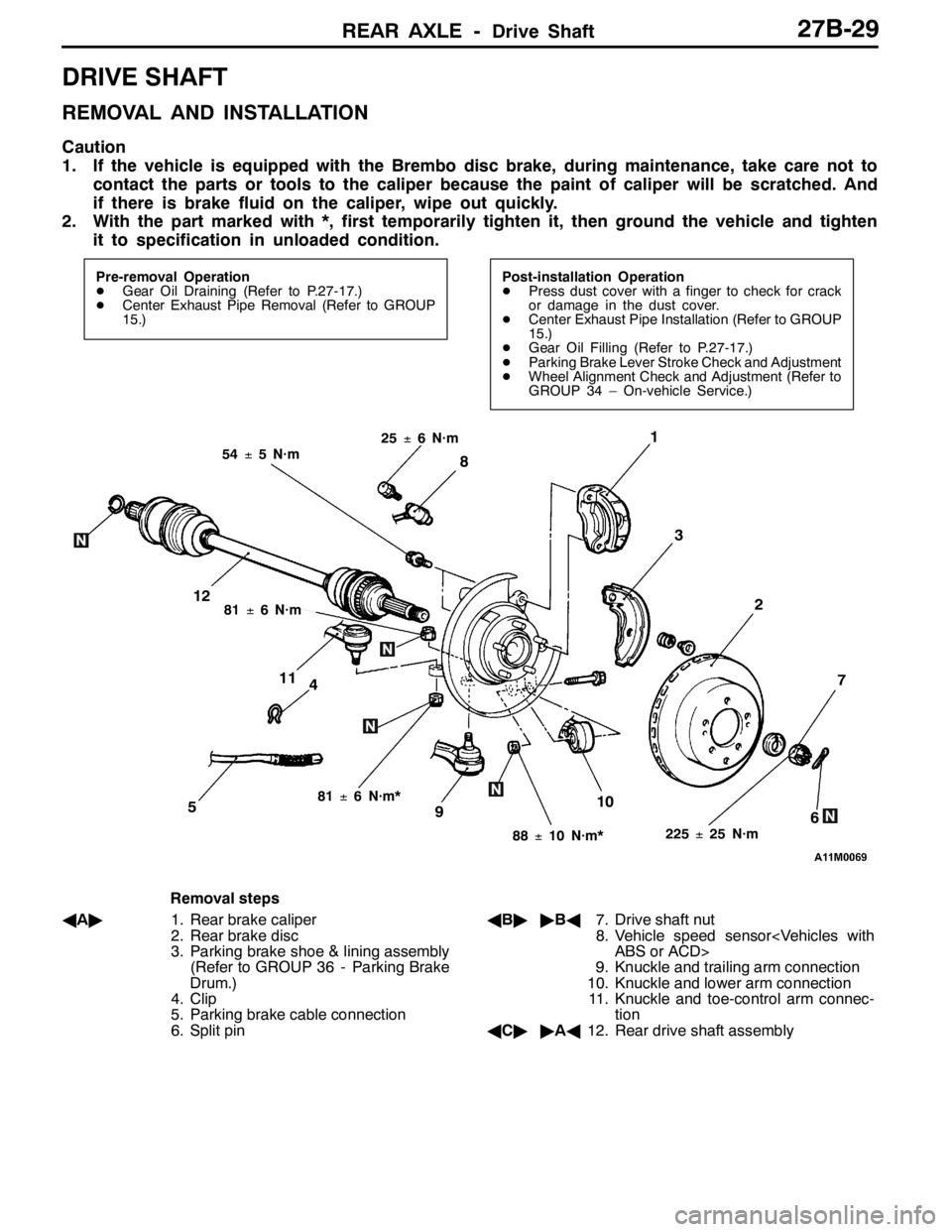
DRIVE SHAFT
REMOVAL AND INSTALLATION
Caution
1. If the vehicle is equipped with the Brembo disc brake, during maintenance, take care not to
contact the parts or tools to the caliper because the paint of caliper will be scratched. And
if there is brake fluid on the caliper, wipe out quickly.
2. With the part marked with *, first temporarily tighten it, then ground the vehicle and tighten
it to specification in unloaded condition.
Pre-removal Operation
DGear Oil Draining (Refer to P.27-17.)
DCenter Exhaust Pipe Removal (Refer to GROUP
15.)Post-installation Operation
DPress dust cover with a finger to check for crack
or damage in the dust cover.
DCenter Exhaust Pipe Installation (Refer to GROUP
15.)
DGear Oil Filling (Refer to P.27-17.)
DParking Brake Lever Stroke Check and Adjustment
DWheel Alignment Check and Adjustment (Refer to
GROUP 34 – On-vehicle Service.)
4
1
3
7
6510
2
8
9
11
12
225±25 N·m
54±5 N·m
88±10 N·m*
81±6 N·m*
81±6 N·m
25±6 N·m
Removal steps
AA"1. Rear brake caliper
2. Rear brake disc
3. Parking brake shoe & lining assembly
(Refer to GROUP 36 - Parking Brake
Drum.)
4. Clip
5. Parking brake cable connection
6. Split pinAB""BA7. Drive shaft nut
8. Vehicle speed sensor
9. Knuckle and trailing arm connection
10. Knuckle and lower arm connection
11. Knuckle and toe-control arm connec-
tion
AC""AA12. Rear drive shaft assembly
Page 994 of 1449

REAR AXLE -Differential Carrier
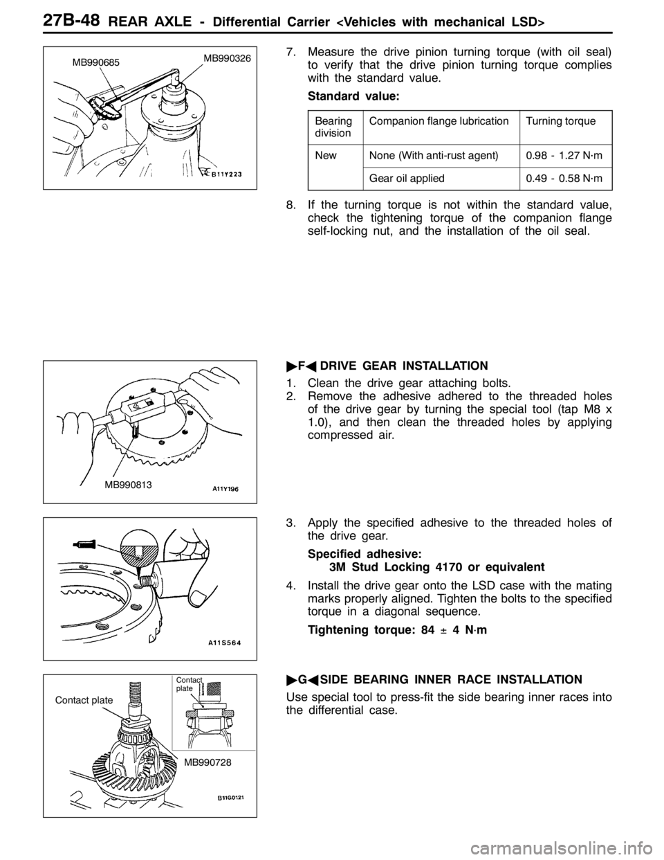
7. Measure the drive pinion turning torque (with oil seal)
to verify that the drive pinion turning torque complies
with the standard value.
Standard value:
Bearing
divisionCompanion flange lubricationTurning torque
NewNone (With anti-rust agent)0.98 - 1.27 N·m
Gear oil applied0.49 - 0.58 N·m
8. If the turning torque is not within the standard value,
check the tightening torque of the companion flange
self-locking nut, and the installation of the oil seal.
"FADRIVE GEAR INSTALLATION
1. Clean the drive gear attaching bolts.
2. Remove the adhesive adhered to the threaded holes
of the drive gear by turning the special tool (tap M8 x
1.0), and then clean the threaded holes by applying
compressed air.
3. Apply the specified adhesive to the threaded holes of
the drive gear.
Specified adhesive:
3M Stud Locking 4170 or equivalent
4. Install the drive gear onto the LSD case with the mating
marks properly aligned. Tighten the bolts to the specified
torque in a diagonal sequence.
Tightening torque: 84±4N
·m
"GASIDE BEARING INNER RACE INSTALLATION
Use special tool to press-fit the side bearing inner races into
the differential case.
MB990326
MB990685
MB990813
Contact plate
MB990728
Contact
plate
Page 998 of 1449

REAR AXLE -Differential Carrier
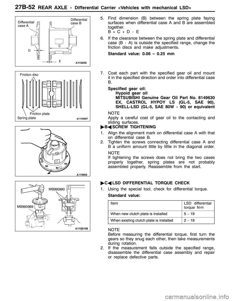
5. Find dimension (B) between the spring plate faying
surfaces when differential case A and B are assembled
together.
B=C+D - E
6. If the clearance between the spring plate and differential
case (B - A) is outside the specified range, change the
friction discs and make adjustments.
Standard value: 0.06 – 0.25 mm
7. Coat each part with the specified gear oil and mount
it in the specified direction and order into differential case
B.
Specified gear oil:
Hypoid gear oil
MITSUBISHI Genuine Gear Oil Part No. 8149630
EX, CASTROL HYPOY LS (GL-5, SAE 90),
SHELL-LSD (GL-5, SAE 80W - 90) or equivalent
NOTE
Apply a careful coat of gear oil to the contacting and
sliding surfaces.
"BASCREW TIGHTENING
1. Align the alignment mark on differential case A with that
on differential case B.
2. Tighten the screws connecting differential case A and
B a uniform amount little by little in the diagonal order.
NOTE
If tightening the screws does not bring the two cases
properly together, spring plates are not probably
assembled properly. Reassemble from the start.
"CALSD DIFFERENTIAL TORQUE CHECK
1. Using the special tool, check for differential torque.
Standard value:
ItemLSD differential
torque N·m
Whennewclutchplateisinstalled5–19When new clutchplateisinstalled5–19
Whenexistingclutchplateisinstalled2–19When existing clutchplateisinstalled2–19
NOTE
Before measuring the differential torque, first turn the
gears so they snug each other, then take measurements
during rotation.
2. If the measurement falls outside the specified range,
disassemble the differential case assembly and repair
or replace defective parts.
D
Differential
case A
E C
Differential
case B
Spring plateFriction plate Friction disc
MB990990
MB990989
Page 999 of 1449

REAR AXLE -Differential Carrier
INSPECTION
DIFFERENTIAL CASE INTERNAL PARTS CONTACT/
SLIDING SURFACE CHECK
1. Clean the disassembled parts with cleaning oil and dry
them with compressed air.
2. Check each plate, disc, and pressure ring for the following:
A. Friction and sliding surfaces of friction discs, friction
plates, and spring plates.
Replace a defective part with heat discoloration and
excessive wear with a new one, as it degrades locking
performance.
NOTE
If the inner periphery of the friction face shows traces
of harsh contact, it is because of the spring tension
of each plate, disc and other part. Do not confuse
this with abnormal wear.
B. Inner periphery and outer periphery protrusions of
friction discs, friction plates, and spring plates.
Replace a cracked or damaged part with a new one.
C. Friction and sliding surfaces between pressure rings
and friction discs.
Grind a dented or scratched part with oil stone and
then lap and correct with a compound on a surface
plate.
NOTE
If the inner periphery of the friction face shows traces
of harsh contact, it is because of the spring tension
of each plate, disc and other part. Do not confuse
this with abnormal wear.
3. Check the following parts for contact and siding surfaces
(D to M) and correct burrs and dents with oil stone.
D: Sliding surfaces of side gear and case
E: Contacting surfaces of differential case and spring
plate
F: Contacting surfaces of pressure ring and differential
case inner face
G: Sliding surfaces of pressure ring hole and side gear
H: Protrusions on outer periphery of pressure ring
I: Pressure ring inner surface and differential pinion
gear spherical surface
J: Pressure ring V-groove and pinion shaft V
K: Sliding surfaces of pinion shaft and differential pinion
gear hole
L: Side gear grooves on outer periphery
M: Slits in inner periphery of differential
Friction disc
A
AB
C B Friction plateFriction plate
Pressure ring
E
D M
F
J
I
H D
G
F
D
K
K
I GLJ E
Page 1063 of 1449

BASIC BRAKE SYSTEM -Disc Brake35A-21
INSTALLATION SERVICE POINT
"AADISC BRAKE ASSEMBLY INSTALLATION
1. In order to measure the brake drag force after pad
installation, measure the rotary-sliding resistance of the
hub by the following procedure with the pads removed.
(1) Withdraw the drive shaft. (Refer to GROUP 26, 27.)
(2) Attach the special tool to the front hub assembly as
shown in the illustration, and tighten it to the specified
torque.
Tightening torque:
245±29 N·m
(3) Use a spring balance to measure the rotary-sliding
resistance of the hub in the forward direction.
2. Install the caliper support to the knuckle, and then
assemble the pad and the clip to the caliper support.
Caution
Do not contaminate the friction surfaces of the pads
and brake discs by any oil or grease.
3. Clean the piston and insert it into the cylinder with the
special tool.
4. Be careful that the piston boot does not become caught,
when lowering the caliper assembly and install the guide
pin to the caliper.
5. Start the engine, and then depress the brake pedal two
or three times strongly. Then stop the engine.
6. Turn the brake disc forward 10 times.
7. Use a spring balance to measure the rotary-sliding
resistance of the hub in the forward direction.
8. Calculate the drag force of the disc brake [difference
between the values measured at steps 1 and 7].
Standard value:
51 N or less
9. If that drag force exceeds the standard value, disassemble
the piston assembly. Then check the piston for
contamination or rust, and confirm if the piston or the
piston seal is deteriorated, and if the slide pins slide
smoothly.
1. Find the drag force of the disc brake. (Refer to P.35A-13.)
Standard value: 69 N or less
2. If that drag force exceeds the standard value, disassemble
the piston assembly. Then check the piston for
contamination or rust, and confirm if the piston or the
piston seal is deteriorated.MB990998
Bolt
MB990998Bolt
MB990520