Page 137 of 172

135
OVERVIEW REPAIRSOPERATION CONTROLS DATA INDEX
SPACE-SAVER SPARE TIRE
*
CHANGING TIRES
9. Pull out the space-saver spare tire
towards the rear underneath the vehi-
cle
10. Position the space-saver spare tire with
the valve facing upwards
11. Unscrew the valve extension from the
valve of the space-saver spare tire
12. Unscrew the dust cap from the exten-
sion and place it on the valve of the
space-saver spare tire.
Due to its different dimensions, the
damaged wheel cannot be placed in
the recess for the space-saver spare tire.<
Driving with the space-saver spare tireDrive cautiously. Do not exceed a speed of
50 mph / 80 km/h.
You must expect changes in vehicle han-
dling such as lower track stability during
braking, longer braking distances and
changes in self-steering properties when
close to the handling limit. These effects
are more pronounced when driving with
winter tires.
Only one space-saver spare tire may
be mounted at one time. Reinstall a
wheel and tire of the original size as soon
as possible.<
Check the tire inflation pressure at
the earliest opportunity and correct it
if necessary. Replace the defective tire as
soon as possible and have the new wheel/
tire assembly balanced.<
Additional safety measures in the
event of a tire change:
Change tires only on a flat, solid and non-
slippery surface.
The vehicle or the jack could slip sideways
on soft or slippery support surfaces, such as
snow, ice, flagstones, etc..
Do not use a wooden block or similar object
as a support base for the jack, as this would
prevent it from extending to its full support
height and reduce its load-carrying capac-
ity.
Do not lie under the vehicle or start the
engine when the vehicle is supported by
the jack – risk of fatal injury.<
Preparing for a tire change
Observe the safety precautions
regarding flat tires on page133.<
1. For vehicles with a space-saver spare
tire:
Place the folding chock behind the front
wheel on the other side of the vehicle;
on downward inclines, place it in front of
this wheel. If the wheel is changed on a
surface with a more severe slope, take
additional precautions to secure the
vehicle from rolling
2. Loosen the lug bolts by a half turn.
Page 138 of 172

136
CHANGING TIRESJacking up the vehicle1. Place the jack at the jacking point closest
to the wheel.
The jack base must be perpendicular to
the surface beneath the jacking point
The vehicle jack is designed for
changing wheels only. Do not
attempt to raise another vehicle model
with it or to raise any load of any kind. To
do so could cause accidents and personal
injury.<
2. During jacking up, insert the jack head in
the square recess of the jacking point
3. Jack the vehicle up until the wheel you
are changing is raised from the ground.Mounting a wheel1. Unscrew the lug bolts and remove the
wheel
2. Remove accumulations of mud or dirt
from the mounting surfaces of the
wheel and hub. Clean the lug bolts.
3. Mount the new wheel
4. Screw at least two lug bolts finger-tight
into opposite bolt holes
5. Screw in the remaining bolts
6. Tighten all the lug bolts firmly in a diag-
onal pattern
7. Lower the vehicle
8. Remove the jack.Tightening the lug boltsTighten the lug bolts in a diagonal pattern.
As soon as possible, have the secure
seating of the lug bolts, tightening
torque 88.5 lb ft/120 Nm, checked using a
calibrated torque wrench. Otherwise, a
wheel coming loose can lead to a severe
accident.<
Replace the defective tire as soon as possi-
ble and have the new wheel/tire assembly
balanced.
Page 139 of 172

137
OVERVIEW REPAIRSOPERATION CONTROLS DATA INDEX
MINI MOBILITY SYSTEM
*
MINI Mobility System
The MINI Mobility System is provided to
help you repair a flat tire. With the help of
this system you can apply a liquid sealant
on the inside of the tire, which seals the
damaged area and enables you to continue
to drive.Preparing for tire repair
Before using the MINI Mobility Sys-
tem read the warning and danger
precautions on the equipment.<
If possible, leave objects in which have
been forced into the tire.
Take off the tag regarding speed limits and
stick it onto the steering wheel.
Using the MINI Mobility SystemIn order to repair a flat tire with the MINI
Mobility System, proceed as follows:
>Pump in liquid sealant, refer to page138
>Reinflate the tire, refer to page138
>Distribute liquid sealant, refer to
page139
>Check tire inflation pressure, refer to
page139
>Drive on, refer to page139.
MINI Mobility System with onboard
tools The MINI Mobility System with tire change
set and onboard tools is located in the lug-
gage compartment under the floor mat:
1Jack
2 Wheel stud wrench
3 Hubcap remover
4 Wrench, screwdriver/Phillips screw-
driver, towing eyelet
5 Compressor, hose with manometer and
plug for cigarette lighter socket
6 Package with filling hose, valve remover
and valve core
7 Filling canister
8 Hex wrench/screwdriver
9 Adapter for wheel lug lock
Page 140 of 172

138
MINI MOBILITY SYSTEM
*
Pumping in liquid sealant
1. Shake the filling canister
2. Screw the filling hose onto the filling
canister
3. Unscrew the dust protection cap from
the valve of the defective tire
4. Screw out the valve core with the valve
remover. The valve remover is located in
a package with the filling hose.
Place the valve core and valve
remover only on clean surfaces.<
5. Remove the cap from the filling hose
6. Push the filling hose onto the tire valve
7. Hold the filling canister with the cap
down and squeeze.
Squeeze the entire contents of the canis-
ter into the tire
8. Remove filling hose
9. Screw valve core into the tire valve with
the valve remover.
In the event of a lost or dirty valve
core you will find another valve core
in a package with the filling hose.
Please remember that the liquid canister
must be replaced every four years if the
equipment has not been used.<
Reinflating the tire1. Screw hose 1 with manometer onto the
tire valve
2. Connect plug 3 to the cigarette lighter
socket in the vehicle interior, refer to
page87
3. Ignition key in position 1:
switch on compressor 2
4. Inflate the tires to at least 26 psi/
180 kPa, but not to more than 36 psi/
250 kPa.
To check the current air pressure, shut
off the device for a short time.
Do not run the compressor for
longer than 6 minutes, otherwise
the device will overheat and possibly be
damaged.<
Page 141 of 172

139
OVERVIEW REPAIRSOPERATION CONTROLS DATA INDEX
MINI MOBILITY SYSTEM
*
If an air pressure of 26 psi/180 kPa
cannot be reached, unscrew the
hose 1 and drive back and forth
about 33 ft/10 m so that the liquid seal-
ant is distributed in the tire. Afterwards
repeat the procedure.
If an air pressure of 26 psi/180 kPa is still
not reached, the tire is too badly dam-
aged. Please contact the nearest MINI
Dealer.<
5. Turn off compressor 2
6. Unscrew hose 1 from the tire valve
7. Store the MINI Mobility System back in
the vehicle.
The instructions for using the MINI
Mobility System are also given on the
equipment.<
Distributing liquid sealantImmediately drive for approx. 10 minutes,
so that the liquid sealant is uniformly dis-
tributed.
Do not exceed a speed of 40 mph /
60 km/h.
If possible do not drive at a speed lower
than 10 mph / 20 km/h.<
Checking tire inflation pressure1. After driving for approx. 10 minutes, pull
over at a suitable location
2. Screw hose with manometer back onto
the tire valve
3. Check the tire inflation pressures.
The tire inflation pressure must be
at least 18 psi/130 kPa. If it is not,
do not continue driving.<
If 18 psi/130 kPa are displayed:
4. Ignition key position 1:
switch on compressor 2. Correct the tire
inflation pressure to the specified value,
refer to the tire inflation pressure table
on page105
5. Replace the tire as soon as possible.
The use of the MINI Mobility System
may be ineffective with tire damage
larger than approx. 1/6in/4mm. Please
contact the nearest MINI Dealer if the tire
cannot be made drivable with the MINI
Mobility System.<
Driving on
Do not exceed the permitted maxi-
mum speed of 50 mph / 80 km/h;
otherwise an accident could happen.<
Replace the defective tire as soon as
possible and have the new wheel/tire
assembly balanced. Have the MINI Mobility
System refilled.<
Tire change setWhen changing a tire, always observe the
safety measures and the procedure for
changing tires starting on page133.
In case of a flat tire the tire change
set is not needed due to the availabil-
ity of the MINI Mobility System.<
Page 142 of 172

140
VEHICLE BATTERYStorage locationMINI COOPER and MINI COOPER Convert-
ible:
The battery is located in the engine com-
partment, refer to page115.
MINI COOPER S and MINI COOPER S Con-
vertible:
The battery is located in the luggage com-
partment under the floor mat.Battery careThe battery is absolutely maintenance-free,
that is, the original electrolyte will normally
last for the service life of the battery under
moderate climatic conditions. Your MINI
Dealer will be glad to advise you if you have
any questions regarding the battery.Charging the batteryOnly charge the battery in the vehicle via
the terminals in the engine compartment
with the engine switched off, refer to
'Jump-starting', page142.
Disposal
After replacing old batteries, return
the used batteries to your MINI
Dealer or to a recycling point. Maintain the
battery in an upright position for transport
and storage. Secure the battery to prevent
it from tilting during transport.<
Power failureAfter a temporary power failure, e.g. due to
a discharged battery, some of your vehicle's
equipment will function only to a limited
extent and must be reinitialized or read-
justed. Individual settings are also lost and
must be reprogrammed:
>The clock must be reset, refer to page67
>The power windows must be reinitial-
ized, refer to page32
>Radio
*:
The stations must be reset, refer to the
Owner's Manual for Radio
>Navigation system
*:
It may take some time for its operability
to be restored, refer to the Owner's Man-
ual for Navigation System.
Page 143 of 172
141
OVERVIEW REPAIRSOPERATION CONTROLS DATA INDEX
FUSES
Do not attempt to repair a blown
fuse or replace it with a fuse of a dif-
ferent color or Ampere rating. To do this
could cause a fire in the vehicle resulting
from a circuit overload.<
If a second fuse blows in the same cir-
cuit, have the cause rectified by your
MINI Dealer.<
A fuse allocation diagram is located on the
inside of the fuse box cover panel.
Plastic tweezers and spare fuses can be
found in the fuse box in the vehicle interior.
In the engine compartmentIn the MINI COOPER and the MINI COOPER
Convertible to the right of the battery.
In the MINI COOPER S and the MINI COO-
PER S Convertible to the right of the air fil-
ter box.
Open the fuse box lid. To do so, press the
clip fastener.
In the vehicle interiorOn the left side of the footwell in the side
trim panel.
Open the fuse box lid. To do so, press the
fastener.
Page 144 of 172

142
JUMP-STARTINGWhen your battery is discharged, you can
use two jumper cables to start your vehicle
with power from the battery in a second
vehicle. Correspondingly you can help start
another vehicle. Only use jumper cables
with fully insulated handles on the termi-
nal clamps.Preparing for jump-starting
Do not touch live wiring and cables
on a running engine. There is a risk of
fatal injury if you do this. Carefully observe
the following instructions to avoid per-
sonal injury and/or damage to either vehi-
cle or both vehicles. Make sure that there is
no contact between the bodywork of the
two vehicles to avoid a short circuit haz-
ard.<
1. Check whether the battery of the sup-
port vehicle has 12 Volts and approxi-
mately the same capacity measured in
Ah. These data are printed on the bat-
tery
2. Switch off the engine of the support
vehicle
3. Switch off any electrical systems and
components in both vehicles.Connect the jumper cables
Always adhere to this sequence when
connecting the jumper cables; failure
to observe this procedure can lead to spark-
ing and pose an injury hazard.<
The illustration shows the auxiliary jump-
starting terminal on the MINI COOPER S
and the MINI COOPER S Convertible.
In the MINI COOPER S and the MINI
COOPER S Convertible, the auxiliary jump-
starting terminal, arrow 1, acts as the posi-
tive battery terminal, refer to view of
engine compartment on page116. The
cover is marked with a +.
1. Remove the cover of the battery or open
the cover of the auxiliary jump-starting
terminal:
>MINI COOPER and MINI COOPER Con-
vertible:
Remove the battery cover.
To do so, press the two clips simulta-
neously.
>MINI COOPER S and MINI COOPER S
Convertible:
 1
1 2
2 3
3 4
4 5
5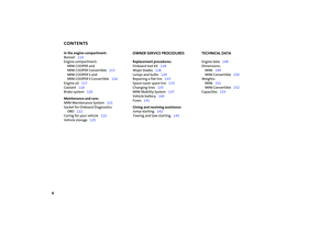 6
6 7
7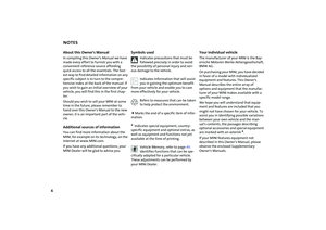 8
8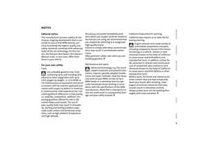 9
9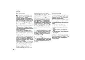 10
10 11
11 12
12 13
13 14
14 15
15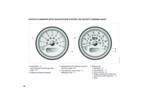 16
16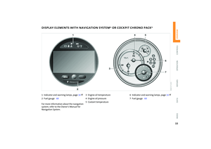 17
17 18
18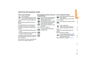 19
19 20
20 21
21 22
22 23
23 24
24 25
25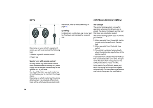 26
26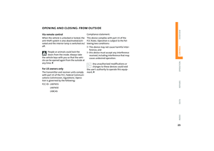 27
27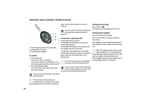 28
28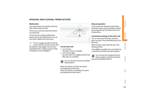 29
29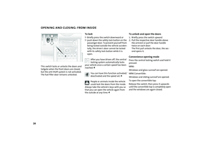 30
30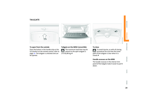 31
31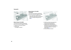 32
32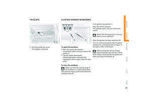 33
33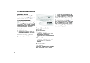 34
34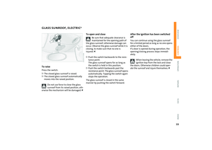 35
35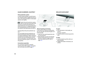 36
36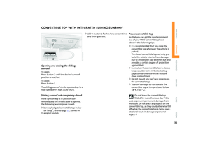 37
37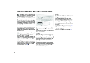 38
38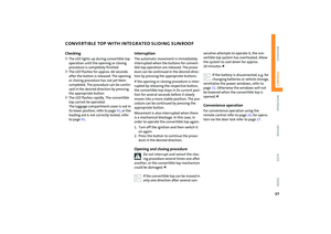 39
39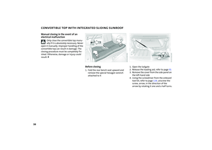 40
40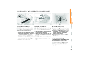 41
41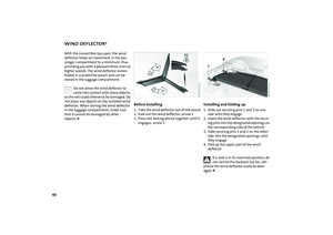 42
42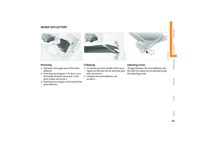 43
43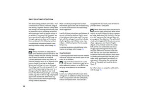 44
44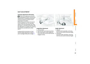 45
45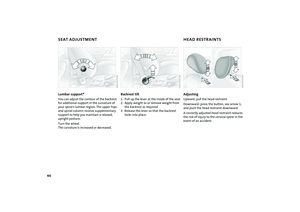 46
46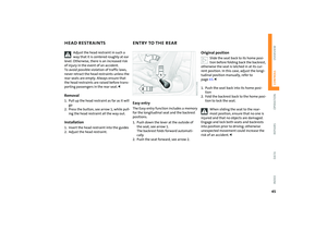 47
47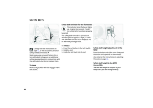 48
48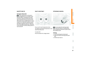 49
49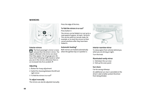 50
50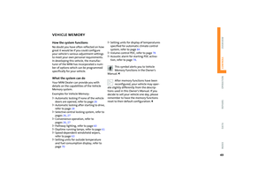 51
51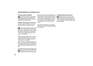 52
52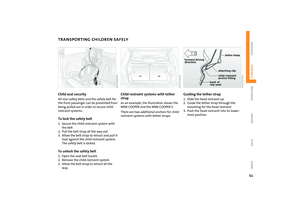 53
53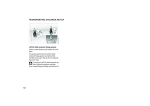 54
54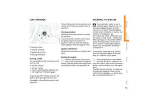 55
55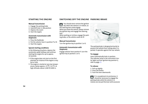 56
56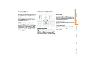 57
57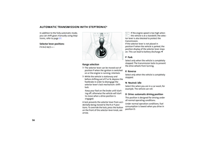 58
58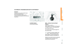 59
59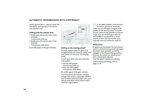 60
60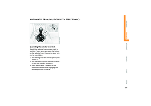 61
61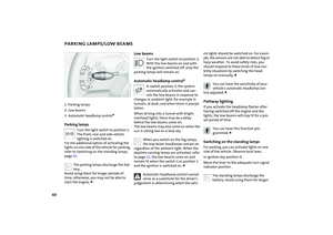 62
62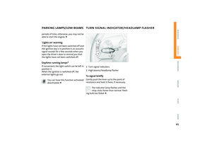 63
63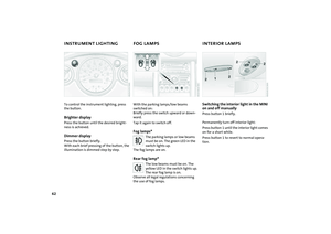 64
64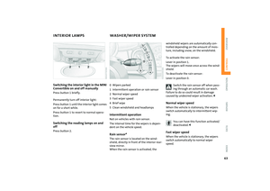 65
65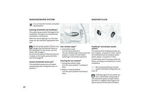 66
66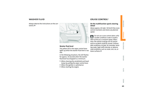 67
67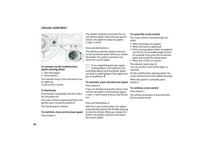 68
68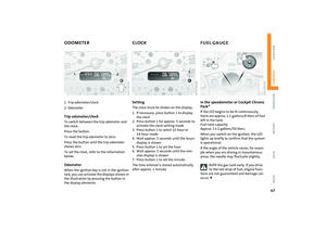 69
69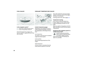 70
70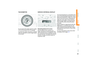 71
71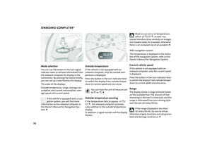 72
72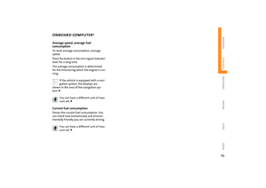 73
73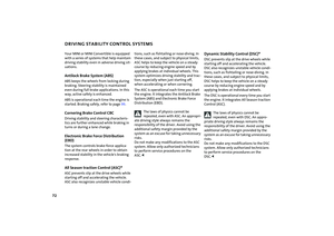 74
74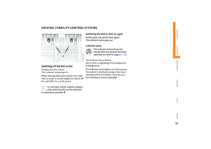 75
75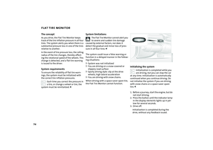 76
76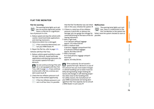 77
77 78
78 79
79 80
80 81
81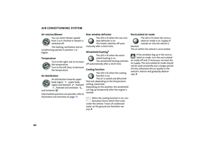 82
82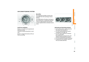 83
83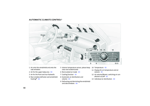 84
84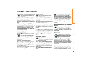 85
85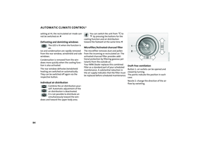 86
86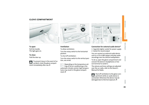 87
87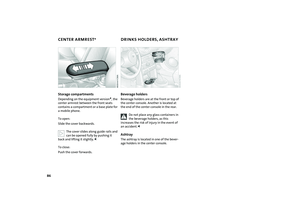 88
88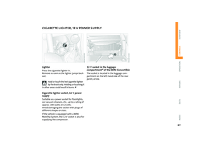 89
89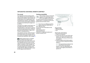 90
90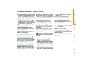 91
91 92
92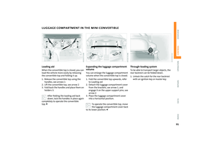 93
93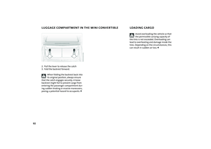 94
94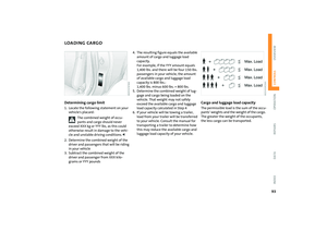 95
95 96
96 97
97 98
98 99
99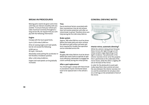 100
100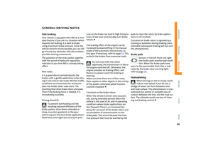 101
101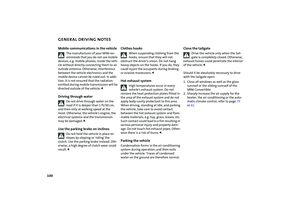 102
102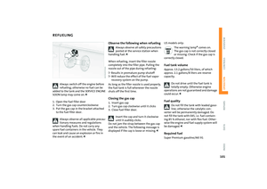 103
103 104
104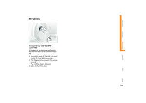 105
105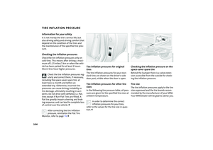 106
106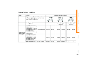 107
107 108
108 109
109 110
110 111
111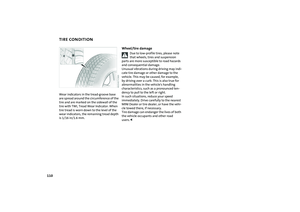 112
112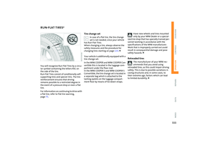 113
113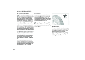 114
114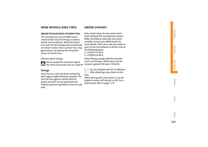 115
115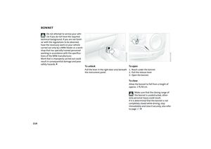 116
116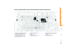 117
117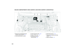 118
118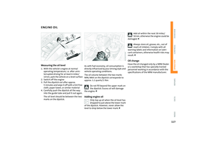 119
119 120
120 121
121 122
122 123
123 124
124 125
125 126
126 127
127 128
128 129
129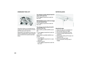 130
130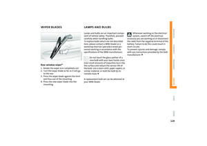 131
131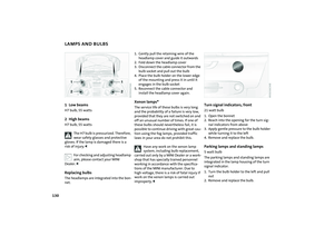 132
132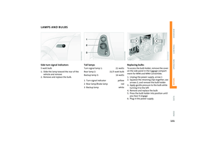 133
133 134
134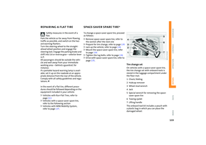 135
135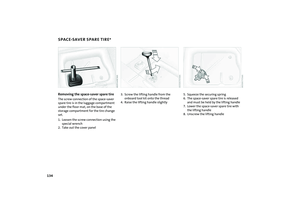 136
136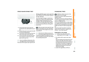 137
137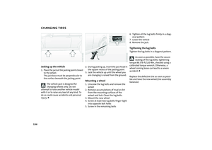 138
138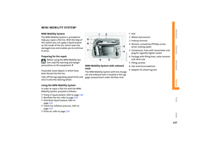 139
139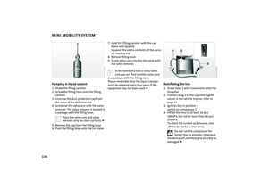 140
140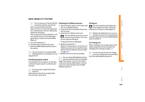 141
141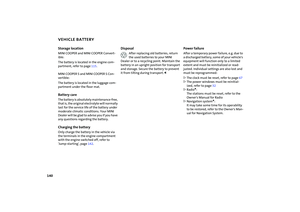 142
142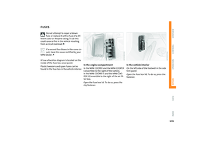 143
143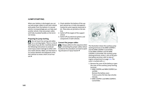 144
144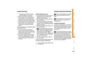 145
145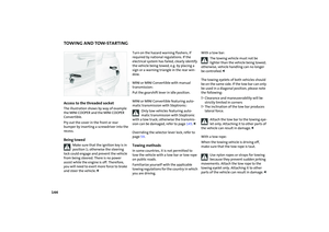 146
146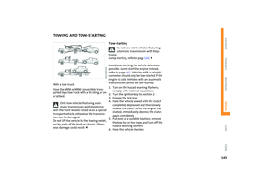 147
147 148
148 149
149 150
150 151
151 152
152 153
153 154
154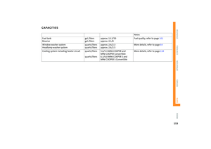 155
155 156
156 157
157 158
158 159
159 160
160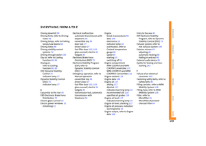 161
161 162
162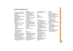 163
163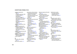 164
164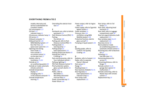 165
165 166
166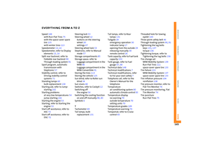 167
167 168
168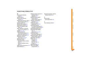 169
169 170
170 171
171