Page 1227 of 1575
Easy Access
1.Description
The easy access function permits automatic rearward movement of the driver seat when the key is removed from
the cylinder. Automatic forward movement of the driver seat will take place when the key is inserted into the
cylinder. This function will be enabled on IMS equipped vehicles when the AUTO button is pressed.
Inhibit Switch should be in P- Position for the Easy Access operation.
2. Functional Diagram
Driver Information
Cluster Indicators
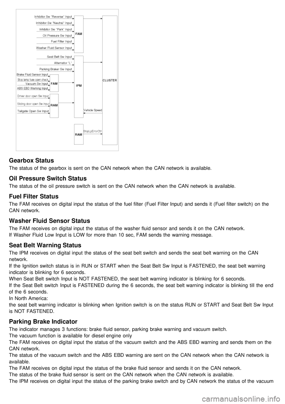
1.The instument cluster indicators listed below are controlled by the In- Panel Module (IPM), Front Area Module
(FAM), or Rear Area Module (RAM) as applicable.
These indicators are:
a. Gearbox status
b. Oil pressure
c. Sediment fuel filter
d. Vacuum
e. Brake fluid
f. Washer fluid
g. Seat belt
h. Park brake
i. Charging voltage
j. Turn indicators
k. High beam
l. Front fog
m. Doors open
n. Tailgate open
o. Stop lamp failure front and rear
2. Functional Diagram
Page 1228 of 1575

Gearbox Status
The status of the gearbox is sent on the CAN network when the CAN network is available.
Oil Pressure Switch Status
The status of the oil pressure switch is sent on the CAN network when the CAN network is available.
Fuel Filter Status
The FAM receives on digital input the status of the fuel filter (Fuel Filter Input) and sends it (Fuel filter switch) on the
CAN network.
Washer Fluid Sensor Status
The FAM receives on digital input the status of the washer fluid sensor and sends it on the CAN network.
If Washer Fluid Low Input is LOW for more than 10 sec, FAM sends the warning message.
Seat Belt Warning Status
The IPM receives on digital input the status of the seat belt switch and sends the seat belt warning on the CAN
network.
If the Ignition switch status is in RUN or START when the Seat Belt Sw Input is FASTENED, the seat belt warning
indicator is blinking for 6 seconds.
When Seat Belt switch Input is NOT FASTENED, the seat belt warning indicator is blinking for 6 seconds.
If the Seat Belt switch Input is FASTENED during the 6 seconds, the seat belt warning indicator is blinking till the end
of the 6 seconds.
In North America:
the seat belt warning indicator is blinking when Ignition switch is on the status RUN or START and Seat Belt Sw Input
is NOT FASTENED.
Parking Brake Indicator
The indicator manages 3 functions: brake fluid sensor, parking brake warning and vacuum switch.
The vacuum function is available for diesel engine only
The FAM receives on digital input the status of the vacuum switch and the ABS EBD warning and sends them on the
CAN network.
The status of the vacuum switch and the ABS EBD warning are sent on the CAN network when the CAN network is
available.
The FAM receives on digital input the status of the brake fluid sensor and sends it on the CAN network.
The status of the brake fluid sensor is sent on the CAN network when the CAN network is available.
The IPM receives on digital input the status of the parking brake switch and by CAN network the status of the vacuum
switch, the status of the ABS EBD warning, the status of the brake fluid sensor and the speed of the vehicle.
Page 1242 of 1575

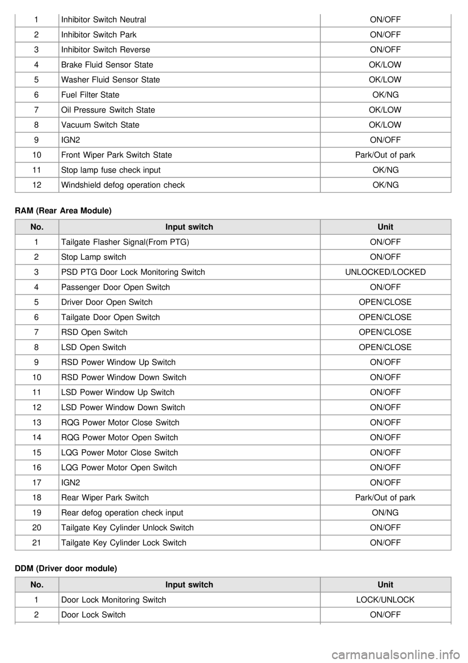
1Inhibitor Switch Neutral ON/OFF
2 Inhibitor Switch Park ON/OFF
3 Inhibitor Switch Reverse ON/OFF
4 Brake Fluid Sensor State OK/LOW
5 Washer Fluid Sensor State OK/LOW
6 Fuel Filter State OK/NG
7 Oil Pressure Switch State OK/LOW
8 Vacuum Switch State OK/LOW
9 IGN2 ON/OFF
10 Front Wiper Park Switch State Park/Out of park
11 Stop lamp fuse check input OK/NG
12 Windshield defog operation check OK/NG
RAM (Rear Area Module) No. Input switch Unit
1 Tailgate Flasher Signal(From PTG) ON/OFF
2 Stop Lamp switch ON/OFF
3 PSD PTG Door Lock Monitoring Switch UNLOCKED/LOCKED
4 Passenger Door Open Switch ON/OFF
5 Driver Door Open Switch OPEN/CLOSE
6 Tailgate Door Open Switch OPEN/CLOSE
7 RSD Open Switch OPEN/CLOSE
8 LSD Open Switch OPEN/CLOSE
9 RSD Power Window Up Switch ON/OFF
10 RSD Power Window Down Switch ON/OFF
11 LSD Power Window Up Switch ON/OFF
12 LSD Power Window Down Switch ON/OFF
13 RQG Power Motor Close Switch ON/OFF
14 RQG Power Motor Open Switch ON/OFF
15 LQG Power Motor Close Switch ON/OFF
16 LQG Power Motor Open Switch ON/OFF
17 IGN2 ON/OFF
18 Rear Wiper Park Switch Park/Out of park
19 Rear defog operation check input ON/NG
20 Tailgate Key Cylinder Unlock Switch ON/OFF
21 Tailgate Key Cylinder Lock Switch ON/OFF
DDM (Driver door module) No. Input switch Unit
1 Door Lock Monitoring Switch LOCK/UNLOCK
2 Door Lock Switch ON/OFF
Page 1309 of 1575

Tolerance(rpm) 5,000
6,0007,0008,000Engine
Revolution (rpm) ±150
±180±210 -Gasoline
±150 ±150 --Diesel
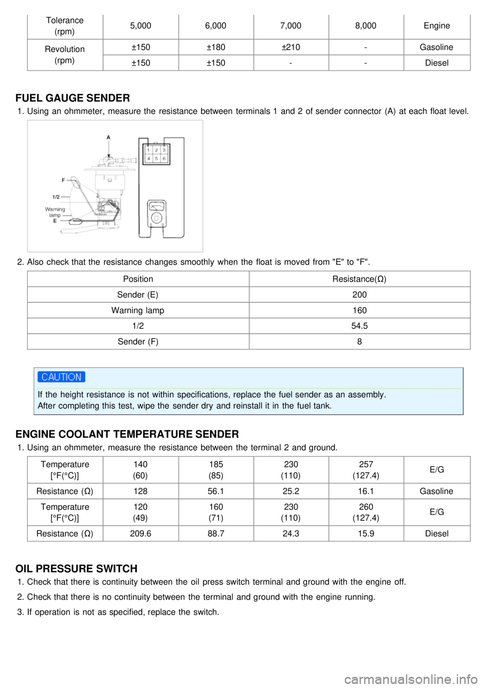
FUEL GAUGE SENDER
1.Using an ohmmeter, measure the resistance between terminals 1 and 2 of sender connector (A) at each float level.
2.Also check that the resistance changes smoothly when the float is moved from "E" to "F".
Position Resistance(Ω)
Sender (E) 200
Warning lamp 160
1/2 54.5
Sender (F) 8
If the height resistance is not within specifications, replace the fuel sender as an assembly.
After completing this test, wipe the sender dry and reinstall it in the fuel tank.
ENGINE COOLANT TEMPERATURE SENDER
1.Using an ohmmeter, measure the resistance between the terminal 2 and ground.
Temperature[°F(°C)] 140
(60) 185
(85) 230
(110) 257
(127.4) E/G
Resistance (Ω) 12856.1 25.216.1Gasoline
Temperature [°F(°C)] 120
(49) 160
(71) 230
(110) 260
(127.4) E/G
Resistance (Ω) 209.688.724.315.9Diesel
OIL PRESSURE SWITCH
1.Check that there is continuity between the oil press switch terminal and ground with the engine off.
2. Check that there is no continuity between the terminal and ground with the engine running.
3. If operation is not as specified, replace the switch.
Page 1310 of 1575
4.Connect the oil pressure switch wire harness.
5. Turn the ignition switch ON. Check that the warning lamp lights up. If the warning lamp doesn't light, test the wire
harness.
BRAKE FLUID LEVEL WARNING SWITCH
1.Remove the connector (A) from the switch located at the brake fluid reservoir (B).
2. Verify that continuity exists between switch terminals 1 and 2 while pressing the switch (float) down with a rod.
BRAKE FLUID LEVEL WARNING LAMP
1.Ignition "ON"
2. Release the parking brake.
3. Remove the connector from the brake fluid level warning switch.
4. Ground the connector at the harness side.
5. Verify that the warning lamp lights.
PARKING BRAKE SWITCH
The parking brake switch is a push type. It is located at the side of the parking brake pedal.
1. Check that there is continuity between the terminal and switch body with the switch (A) ON.
Page 1414 of 1575
2007 > 2.7L V6 GASOLINE >
INSPECTION
Wrap tin foil around the end of the voltmeter test lead to prevent damaging the heater line. Apply finger pressure
on the tin foil, moving the tin foil along the grid line to check for open circuits.
1.Turn on the defogger switch and use a voltmeter to measure the voltage of each heater line at the glass center
point. If a voltage of approximately 6V is indicated by the voltmeter, the heater line of the rear window is
considered satisfactory.
2.If a heater line is burned out between the center point and (+) terminal, the voltmeter will indicate 12V.
3.If a heater line is burned out between the center point and ( - ) terminal, the voltmeter will indicate 0V.
Page 1562 of 1575
2007 > 2.7L V6 GASOLINE >
DESCRIPTION
SELF ADJUSTING CLUTCH(S.A.C.) COVER
a. As a clutch disc facing is worn away according to its durability, a cover weight is increasing and a clutch pedal
pressure can be more needed.
b. To make up for this defect, the self adjusting clutch system makes the requsted pedal pressure minimized so that
makes the maintenance cycle longer.
CONCENTRIC SLAVE CYLINDER-C.S.C.
It improves working efficiency and lowers the number and the weight of part by unifing clutch release control
parts(clutch release bearing ~ clutch release cylinder) in a manual transaxle.
OPERATION
CONCENTRIC SLAVE CYLINDER-C.S.C
When the clutch pedal is pressed, oil pressure is transmitted along the arrow directions shown below and that moves
the clutch slave cylinder and the diaphragm spring of the clutch cover.