Page 1310 of 1575
4.Connect the oil pressure switch wire harness.
5. Turn the ignition switch ON. Check that the warning lamp lights up. If the warning lamp doesn't light, test the wire
harness.
BRAKE FLUID LEVEL WARNING SWITCH
1.Remove the connector (A) from the switch located at the brake fluid reservoir (B).
2. Verify that continuity exists between switch terminals 1 and 2 while pressing the switch (float) down with a rod.
BRAKE FLUID LEVEL WARNING LAMP
1.Ignition "ON"
2. Release the parking brake.
3. Remove the connector from the brake fluid level warning switch.
4. Ground the connector at the harness side.
5. Verify that the warning lamp lights.
PARKING BRAKE SWITCH
The parking brake switch is a push type. It is located at the side of the parking brake pedal.
1. Check that there is continuity between the terminal and switch body with the switch (A) ON.
Page 1312 of 1575
SEAT BELT WARNING LAMP
With the ignition switch turned ON, verify that the lamp glows.Seat belt condition Warning lamp
Fastened OFF
Not fastened ON
Page 1369 of 1575

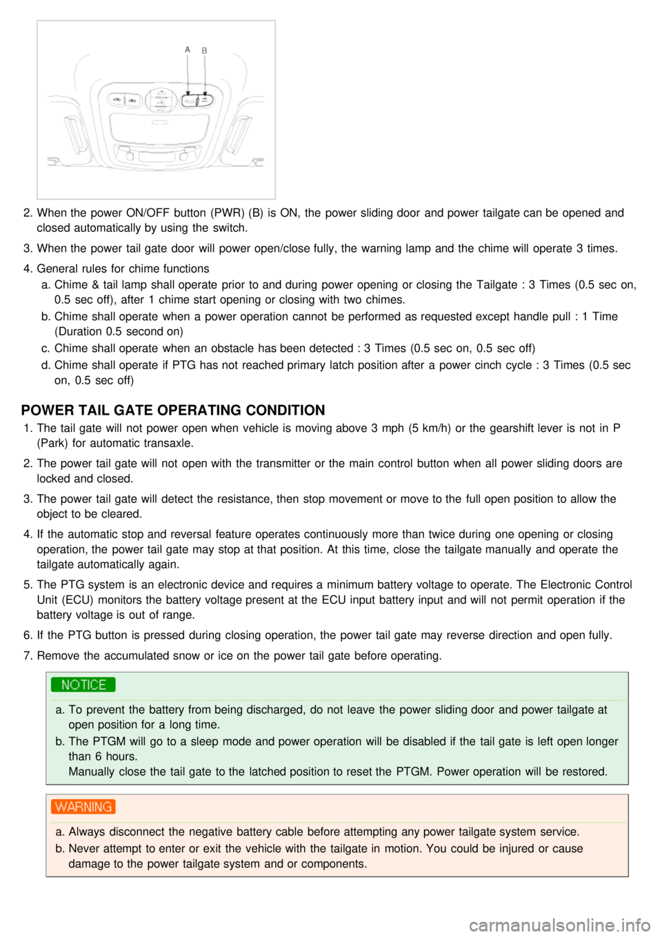
2.When the power ON/OFF button (PWR) (B) is ON, the power sliding door and power tailgate can be opened and
closed automatically by using the switch.
3. When the power tail gate door will power open/close fully, the warning lamp and the chime will operate 3 times.
4. General rules for chime functions
a. Chime & tail lamp shall operate prior to and during power opening or closing the Tailgate : 3 Times (0.5 sec on,
0.5 sec off), after 1 chime start opening or closing with two chimes.
b. Chime shall operate when a power operation cannot be performed as requested except handle pull : 1 Time
(Duration 0.5 second on)
c. Chime shall operate when an obstacle has been detected : 3 Times (0.5 sec on, 0.5 sec off)
d. Chime shall operate if PTG has not reached primary latch position after a power cinch cycle : 3 Times (0.5 sec
on, 0.5 sec off)
POWER TAIL GATE OPERATING CONDITION
1.The tail gate will not power open when vehicle is moving above 3 mph (5 km/h) or the gearshift lever is not in P
(Park) for automatic transaxle.
2. The power tail gate will not open with the transmitter or the main control button when all power sliding doors are
locked and closed.
3. The power tail gate will detect the resistance, then stop movement or move to the full open position to allow the
object to be cleared.
4. If the automatic stop and reversal feature operates continuously more than twice during one opening or closing
operation, the power tail gate may stop at that position. At this time, close the tailgate manually and operate the
tailgate automatically again.
5. The PTG system is an electronic device and requires a minimum battery voltage to operate. The Electronic Control
Unit (ECU) monitors the battery voltage present at the ECU input battery input and will not permit operation if the
battery voltage is out of range.
6. If the PTG button is pressed during closing operation, the power tail gate may reverse direction and open fully.
7. Remove the accumulated snow or ice on the power tail gate before operating.
a.To prevent the battery from being discharged, do not leave the power sliding door and power tailgate at
open position for a long time.
b. The PTGM will go to a sleep mode and power operation will be disabled if the tail gate is left open longer
than 6 hours.
Manually close the tail gate to the latched position to reset the PTGM. Power operation will be restored.
a.Always disconnect the negative battery cable before attempting any power tailgate system service.
b. Never attempt to enter or exit the vehicle with the tailgate in motion. You could be injured or cause
damage to the power tailgate system and or components.
Page 1533 of 1575

2007 > 2.7L V6 GASOLINE >
DESCRIPTION
When reversing, the driver is not easy to find objects in the blind spots and to determine the distance from the object.
In order to provide the driver safety and convenience, back warning system will operate upon shifting to "R" Ultrasonic
sensor will emit ultrasonic wave rearward and detect the reflected wave. Control unit will calculate distance to the
object using the sensor signal input and output buzzer alarm in three steps (first, second and third alarm).
ALARM RANGE
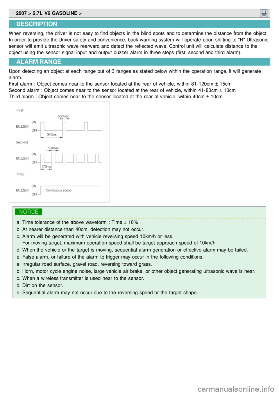
Upon detecting an object at each range out of 3 ranges as stated below within the operation range, it will generate
alarm.
First alarm : Object comes near to the sensor located at the rear of vehicle, within 81- 120cm ± 15cm
Second alarm : Object comes near to the sensor located at the rear of vehicle, within 41- 80cm ± 10cm
Third alarm : Object comes near to the sensor located at the rear of vehicle, within 40cm ± 10cm
a.Time tolerance of the above waveform : Time ± 10%
b. At nearer distance than 40cm, detection may not occur.
c. Alarm will be generated with vehicle reversing speed 10km/h or less.
For moving target, maximum operation speed shall be target approach speed of 10km/h.
d. When the vehicle or the target is moving, sequential alarm generation or effective alarm may be failed.
e. False alarm, or failure of the alarm to trigger may occur in the following conditions.
a. Irregular road surface, gravel road, reversing toward grass.
b. Horn, motor cycle engine noise, large vehicle air brake, or other object generating ultrasonic wave is near.
c. When a wireless transmitter is used near to the sensor.
d. Dirt on the sensor.
e. Sequential alarm may not occur due to the reversing speed or the target shape.
Page 1535 of 1575
2007 > 2.7L V6 GASOLINE >
DIAGNOSIS
1.DIAGNOSIS
Turn the ignition switch ON, then shift the transaxle lever to 'R'. The Back Warning System is then checked.
If no trouble, it generates buzzer alarm sound for 0.3 seconds after 0.5 seconds from power approval. In case of
system failure, buzzer alarm is generated 3 times continuously with the interval of 0.3 seconds.
2.DIAGNOSIS MODE
Switch on diagnosis mode upon system failure.
In case of system failure, then it indicates the failed point as follows.
SENSOR CONNECTION CHECKING
Page 1536 of 1575

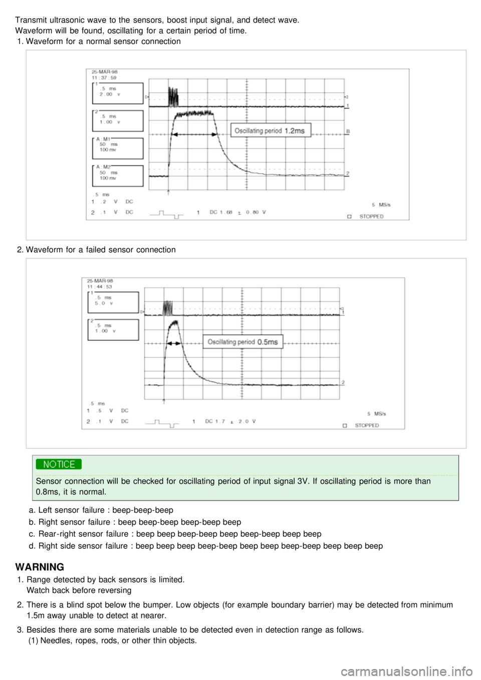
Transmit ultrasonic wave to the sensors, boost input signal, and detect wave.
Waveform will be found, oscillating for a certain period of time.1. Waveform for a normal sensor connection
2.Waveform for a failed sensor connection
Sensor connection will be checked for oscillating period of input signal 3V. If oscillating period is more than
0.8ms, it is normal.
a. Left sensor failure : beep- beep- beep
b. Right sensor failure : beep beep- beep beep- beep beep
c. Rear - right sensor failure : beep beep beep- beep beep beep- beep beep beep
d. Right side sensor failure : beep beep beep beep- beep beep beep beep- beep beep beep beep
WARNING
1.Range detected by back sensors is limited.
Watch back before reversing
2. There is a blind spot below the bumper. Low objects (for example boundary barrier) may be detected from minimum
1.5m away unable to detect at nearer.
3. Besides there are some materials unable to be detected even in detection range as follows.
(1) Needles, ropes, rods, or other thin objects.
Page 1539 of 1575
2007 > 2.7L V6 GASOLINE >
REPLACEMENT
1.Remove the right side trim of the trunk (Refer to the Body group - "Interior trim")
2. Loosen the mounting bolts and remove the back warning control unit (A) from the quarter panel.
Page 1541 of 1575

2007 > 2.7L V6 GASOLINE >
Operation principle
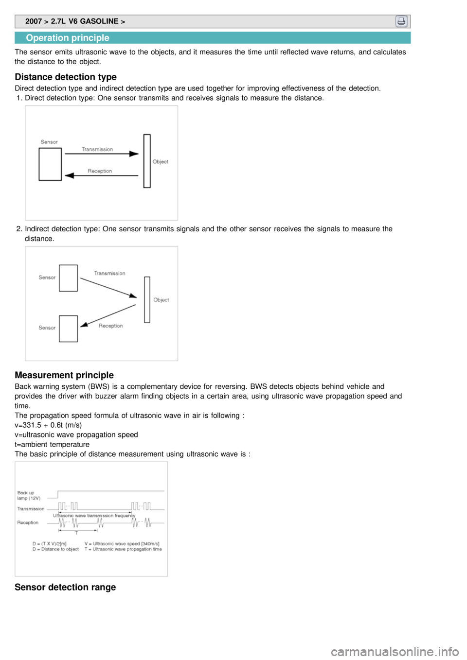
The sensor emits ultrasonic wave to the objects, and it measures the time until reflected wave returns, and calculates
the distance to the object.
Distance detection type
Direct detection type and indirect detection type are used together for improving effectiveness of the detection.
1. Direct detection type: One sensor transmits and receives signals to measure the distance.
2.Indirect detection type: One sensor transmits signals and the other sensor receives the signals to measure the
distance.
Measurement principle
Back warning system (BWS) is a complementary device for reversing. BWS detects objects behind vehicle and
provides the driver with buzzer alarm finding objects in a certain area, using ultrasonic wave propagation speed and
time.
The propagation speed formula of ultrasonic wave in air is following :
v=331.5 + 0.6t (m/s)
v=ultrasonic wave propagation speed
t=ambient temperature
The basic principle of distance measurement using ultrasonic wave is :
Sensor detection range