2007 KIA CARNIVAL warning
[x] Cancel search: warningPage 1205 of 1575
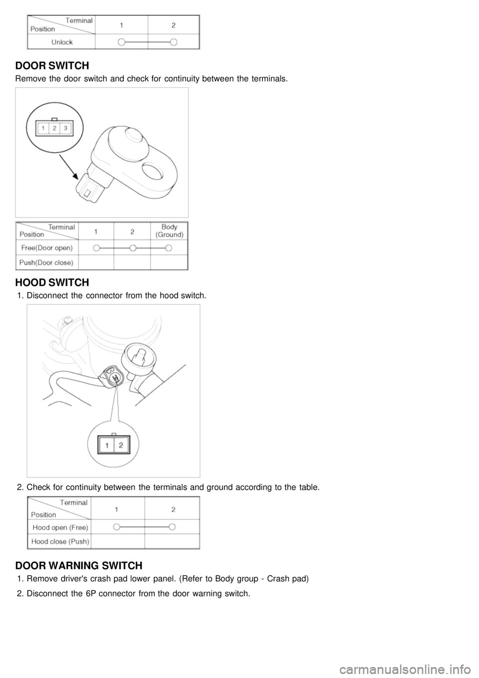
DOOR SWITCH
Remove the door switch and check for continuity between the terminals.
HOOD SWITCH
1.Disconnect the connector from the hood switch.
2.Check for continuity between the terminals and ground according to the table.
DOOR WARNING SWITCH
1.Remove driver's crash pad lower panel. (Refer to Body group - Crash pad)
2. Disconnect the 6P connector from the door warning switch.
Page 1211 of 1575
2007 > 2.7L V6 GASOLINE >
DESCRIPTION
All modules are linked a low speed CAN network.
The input information for the modules is coming from both the CAN network and the hardware components
(actuatorsand sensors).
a. FAM (Front Area Module)
a. Headlamp low/high beam control (with DRL)
b. Park lamp control
c. Front fog lamp control
d. Front turn signal lamp control
e. Windshield wiper control
f. Windshield deicer
g. Diagnostics
b. IPM (In - Panel Module)
a. RKE (Remote Keyless Control)
b. VAS (Voice Alarm System)
c. Ignition key hole illumination
d. Switch indicators control
e. Panel light control
f. Seat belt warning
g. Auto light/DRL control (Logic)
h. Windshield/Rear wiper control (Logic)
i. Turn and Hazard lamp control (Logic)
j. Central door lock (Logic)
k. Windshield deicer timer
l. Rear glass defog timer
m. Gateway for ISO- 9141 (K- Line)
c. RAM (Rear Area Module)
a. Tail lamp control
b. Turn and Hazard lamp control
c. Back up lamp control
d. Rea fog lamp control
e. Stop lamp outage detection
f. Sliding door power window/Quarter glass control
g. Room lamp control
h. Rear wiper control
i. Rear glass defog
j. Fuel filler door open solenoid control
d. ADM (Assist Drive Module)
e. DDM (Driver Drive Module)
MODULE INTRODUCTION
FAM/IPM/RAM consists of a power board and an electronic board. The power board contains circuit protection devices
and switching devices. The electronic board uses Intelligent Power Switching (IPS) for HS/LS load control, logic
functions and CAN/K- Line communication. The power board and electronic board are connected with pin blocks for
the Front Area Module (FAM) and VCD (Variable Connection Displacement) for the In- Panel Module (IPM) and the
Rear Area Module (RAM).
Page 1228 of 1575
Gearbox Status
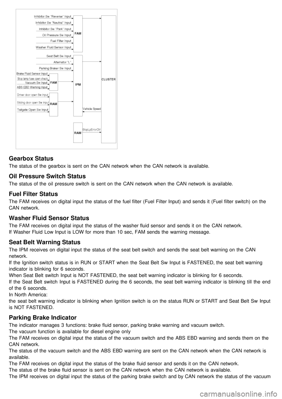
The status of the gearbox is sent on the CAN network when the CAN network is available.
Oil Pressure Switch Status
The status of the oil pressure switch is sent on the CAN network when the CAN network is available.
Fuel Filter Status
The FAM receives on digital input the status of the fuel filter (Fuel Filter Input) and sends it (Fuel filter switch) on the
CAN network.
Washer Fluid Sensor Status
The FAM receives on digital input the status of the washer fluid sensor and sends it on the CAN network.
If Washer Fluid Low Input is LOW for more than 10 sec, FAM sends the warning message.
Seat Belt Warning Status
The IPM receives on digital input the status of the seat belt switch and sends the seat belt warning on the CAN
network.
If the Ignition switch status is in RUN or START when the Seat Belt Sw Input is FASTENED, the seat belt warning
indicator is blinking for 6 seconds.
When Seat Belt switch Input is NOT FASTENED, the seat belt warning indicator is blinking for 6 seconds.
If the Seat Belt switch Input is FASTENED during the 6 seconds, the seat belt warning indicator is blinking till the end
of the 6 seconds.
In North America:
the seat belt warning indicator is blinking when Ignition switch is on the status RUN or START and Seat Belt Sw Input
is NOT FASTENED.
Parking Brake Indicator
The indicator manages 3 functions: brake fluid sensor, parking brake warning and vacuum switch.
The vacuum function is available for diesel engine only
The FAM receives on digital input the status of the vacuum switch and the ABS EBD warning and sends them on the
CAN network.
The status of the vacuum switch and the ABS EBD warning are sent on the CAN network when the CAN network is
available.
The FAM receives on digital input the status of the brake fluid sensor and sends it on the CAN network.
The status of the brake fluid sensor is sent on the CAN network when the CAN network is available.
The IPM receives on digital input the status of the parking brake switch and by CAN network the status of the vacuum
switch, the status of the ABS EBD warning, the status of the brake fluid sensor and the speed of the vehicle.
Page 1229 of 1575
switch, the status of the ABS EBD warning, the status of the brake fluid sensor and the speed of the vehicle.
The IPM sends the park brake indicator control on the CAN network.
The indicator is lighted if the vacuum switch or ABS EBD warning are on or brake fluid sensor is low or park brake
switch is on.
If the speed of the vehicle is over 10 km/h and ignition switch is on the status RUN the park brake indicator control is
blinking at 50% duty in 0.6 second if Parking Brake switch Input is active. In this case Vacuum switch, ABS EBD
warning and Brake Fluid sensor are ignored.
The park brake indicator is blinking on the same time that the chime is ringing. If a CAN signal among Vacuum switch,
EBD warning or Brake Fluid Sens switch is INVALID, out of range or not received this CAN signal is considered to be
OFF.
If VehicleSpeed CAN signal is INVALID or not received, it is considered to be 0 kph.
Charging Voltage Control
The IPM receives on analog input the voltage of generator and sends a warning.
When the voltage of generator L pass strictly above 10V, the state of the CAN variable.
Turn Indicators Status
The status of the turn indicators are sent on the CAN network when the CAN network is available.
High Beam Status
The status of the high beam is sent on the CAN network when the CAN network is available.
Front Fog Lamp Status
The status of the front fog lamp (lightning and state of the bulbs) is sent on the CAN network when the CAN network
is available.
Doors Open Warning
The RAM receives on digital input the status of the driver door open switch and sends it on the CAN network.
The RAM receives on digital input the status of the passenger door open switch and sends it on the CAN network.
The RAM receives on digital input the status of the left sliding door open switch and sends it on the CAN network.
The RAM receives on digital input the status of the right sliding door open switch and sends it on the CAN network.
When vehicle speed is under 10 kph, with ignition key not inserted and any door OPEN, DoorsOpenWngCtrl stays ON
for 20 min and then is turned OFF.
Tailgate Open Switch Status
When vehicle speed is under 10 kph, ignition key is inserted and Tailgate open switch is OPEN, Tailgate Open
warning stays ON forever (IPM can enter sleep mode).
When vehicle speed is under 10 kph, with ignition key not inserted and lgate open switch is OPEN, Tailgate Open
warning stays ON for 20 min and then is turned OFF.
Chime Control
1.The chime warns the driver that a problem is occurred.
These warning are:
a. Seat belt
b. Parking on
c. Over speed
d. Key reminder
e. Light Warning
f. Doors Open
g. Tailgate open warning
2. Chime sound priority:
a. 1st : Seatbelt warning
b. 2nd : Overspeed warning
c. 3rd : Door open warning
d. 4th : T/Gate open warning
e. 5th : Key operated warning
f. 6th : Parking Brake warning
Page 1230 of 1575
g.7th : Light ON warning
h. 8th : Key learning sound
3. If two different warning condition happen at the same time, chime should work only for the highest warning
condition.
4. Cluster indicators should work for two warning behavior.
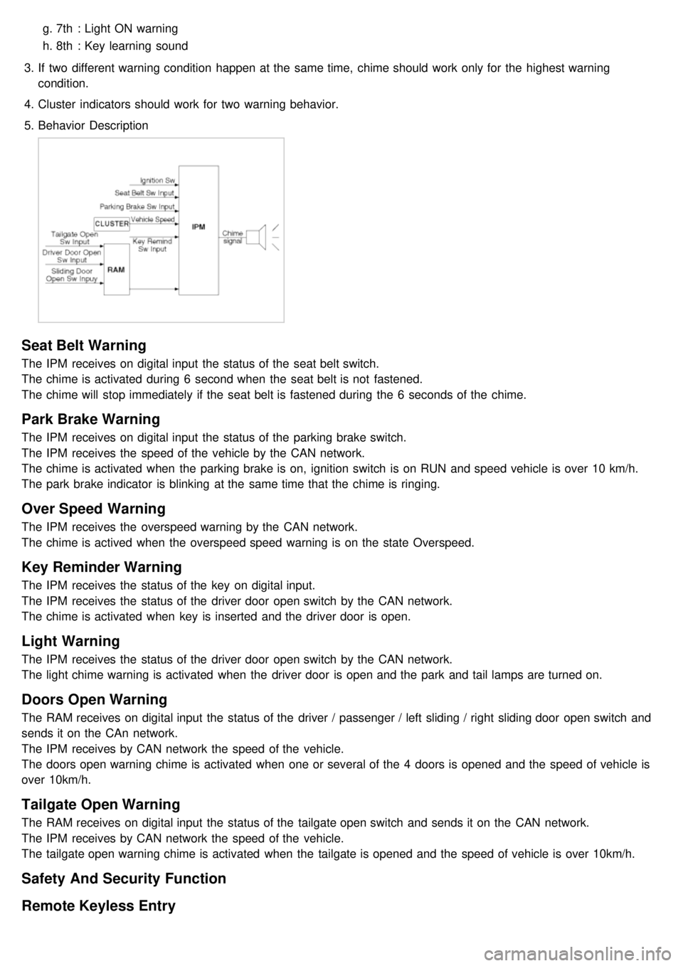
5. Behavior Description
Seat Belt Warning
The IPM receives on digital input the status of the seat belt switch.
The chime is activated during 6 second when the seat belt is not fastened.
The chime will stop immediately if the seat belt is fastened during the 6 seconds of the chime.
Park Brake Warning
The IPM receives on digital input the status of the parking brake switch.
The IPM receives the speed of the vehicle by the CAN network.
The chime is activated when the parking brake is on, ignition switch is on RUN and speed vehicle is over 10 km/h.
The park brake indicator is blinking at the same time that the chime is ringing.
Over Speed Warning
The IPM receives the overspeed warning by the CAN network.
The chime is actived when the overspeed speed warning is on the state Overspeed.
Key Reminder Warning
The IPM receives the status of the key on digital input.
The IPM receives the status of the driver door open switch by the CAN network.
The chime is activated when key is inserted and the driver door is open.
Light Warning
The IPM receives the status of the driver door open switch by the CAN network.
The light chime warning is activated when the driver door is open and the park and tail lamps are turned on.
Doors Open Warning
The RAM receives on digital input the status of the driver / passenger / left sliding / right sliding door open switch and
sends it on the CAn network.
The IPM receives by CAN network the speed of the vehicle.
The doors open warning chime is activated when one or several of the 4 doors is opened and the speed of vehicle is
over 10km/h.
Tailgate Open Warning
The RAM receives on digital input the status of the tailgate open switch and sends it on the CAN network.
The IPM receives by CAN network the speed of the vehicle.
The tailgate open warning chime is activated when the tailgate is opened and the speed of vehicle is over 10km/h.
Safety And Security Function
Remote Keyless Entry
Page 1246 of 1575
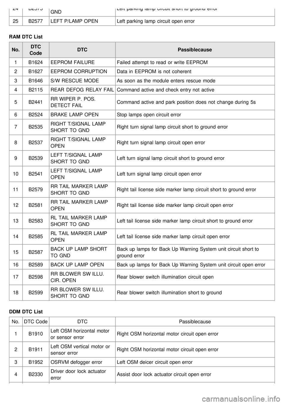
24B2575
GND Left parking lamp circuit short to ground error
25 B2577 LEFT P/LAMP OPEN Left parking lamp circuit open error
RAM DTC List No. DTC
Code DTC
Passiblecause
1 B1624 EEPROM FAILURE Failed attempt to read or write EEPROM
2 B1627 EEPROM CORRUPTION Data in EEPROM is not coherent
3 B1646 S/W RESCUE MODE As soon as the module enters rescue mode
4 B2115 REAR DEFOG RELAY FAIL Command active and check entry not active
5 B2441 RR WIPER P. POS.
DETECT FAIL Command active and park position does not change during 5s
6 B2524 BRAKE LAMP OPEN Stop lamps open circuit error
7 B2535 RIGHT T/SIGNAL LAMP
SHORT TO GND Right turn signal lamp circuit short to ground error
8 B2537 RIGHT T/SIGNAL LAMP
OPEN Right turn signal lamp circuit open error
9 B2539 LEFT T/SIGNAL LAMP
SHORT TO GND Left turn signal lamp circuit short to ground error
10 B2541 LEFT T/SIGNAL LAMP
OPEN Left turn signal lamp circuit open error
11 B2579 RR TAIL MARKER LAMP
SHORT TO GND Right tail license side marker lamp circuit short to ground error
12 B2581 RR TAIL MARKER LAMP
OPEN Right tail license side marker lamp circuit open error
13 B2583 RL TAIL MARKER LAMP
SHORT TO GND Left tail license side marker lamp circuit short to ground error
14 B2585 RL TAIL MARKER LAMP
OPEN Left tail license side marker lamp circuit open error
15 B2587 BACK UP LAMP SHORT
TO GND Back up lamps for Back Up Warning System unit circuit short to
ground error
16 B2589 BACK UP LAMP OPEN Back up lamps for Back Up Warning System unit circuit open error
17 B2598 RR BLOWER SW ILLU.
CIR. OPEN Rear blower switch illumination circuit open
18 B2599 RR BLOWER SW ILLU.
SHORT TO GND Rear blower switch illumination short to ground
DDM DTC List No. DTC Code DTC Passiblecause
1 B1910 Left OSM horizontal motor
or sensor error Right OSM horizontal motor circuit open error
2 B1911 Left OSM vertical motor or
sensor error Right OSM horizontal motor circuit open error
3 B1952 OSRVM defogger error Left OSM deicer circuit open error
4 B2330 Driver door lock actuator
error Assist door lock actuator circuit open error
Page 1249 of 1575
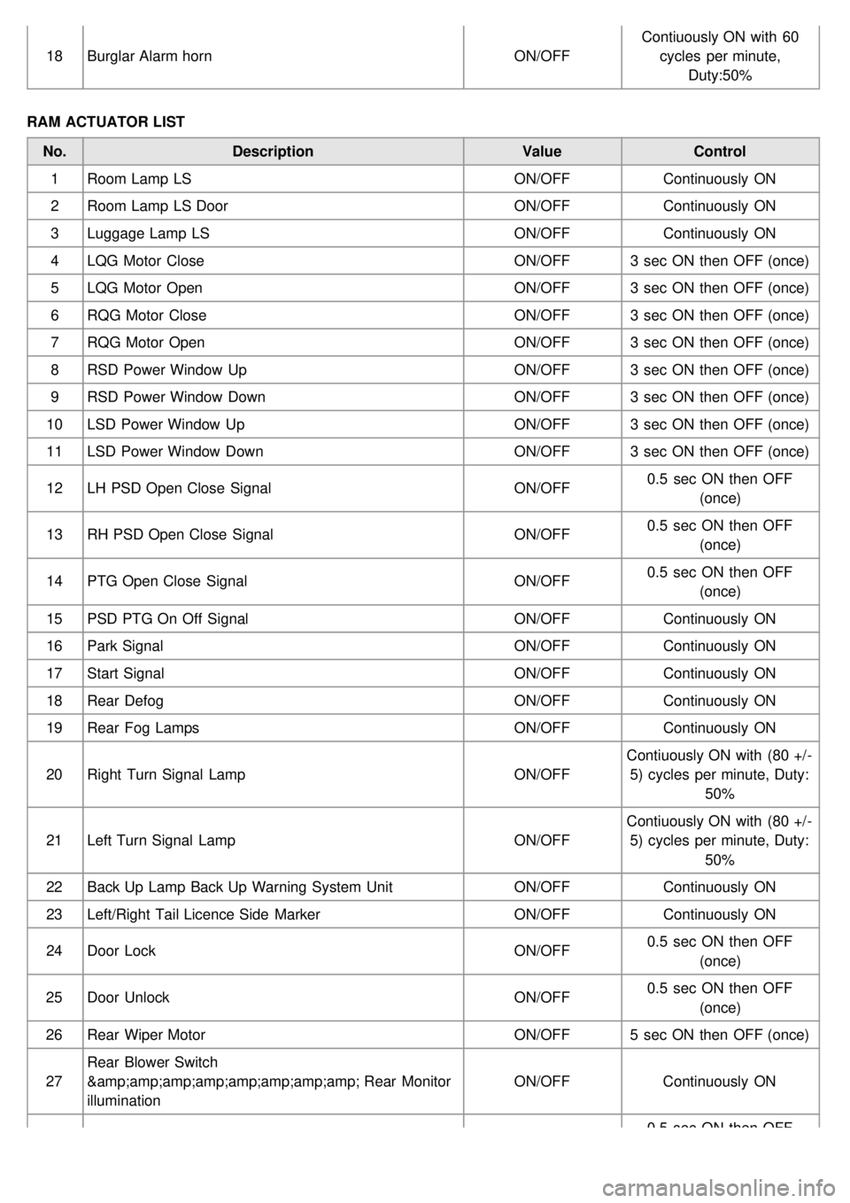
18Burglar Alarm horn ON/OFFContiuously ON with 60
cycles per minute, Duty:50%
RAM ACTUATOR LIST No. Description ValueControl
1 Room Lamp LS ON/OFFContinuously ON
2 Room Lamp LS Door ON/OFFContinuously ON
3 Luggage Lamp LS ON/OFFContinuously ON
4 LQG Motor Close ON/OFF3 sec ON then OFF (once)
5 LQG Motor Open ON/OFF3 sec ON then OFF (once)
6 RQG Motor Close ON/OFF3 sec ON then OFF (once)
7 RQG Motor Open ON/OFF3 sec ON then OFF (once)
8 RSD Power Window Up ON/OFF3 sec ON then OFF (once)
9 RSD Power Window Down ON/OFF3 sec ON then OFF (once)
10 LSD Power Window Up ON/OFF3 sec ON then OFF (once)
11 LSD Power Window Down ON/OFF3 sec ON then OFF (once)
12 LH PSD Open Close Signal ON/OFF0.5 sec ON then OFF
(once)
13 RH PSD Open Close Signal ON/OFF0.5 sec ON then OFF
(once)
14 PTG Open Close Signal ON/OFF0.5 sec ON then OFF
(once)
15 PSD PTG On Off Signal ON/OFFContinuously ON
16 Park Signal ON/OFFContinuously ON
17 Start Signal ON/OFFContinuously ON
18 Rear Defog ON/OFFContinuously ON
19 Rear Fog Lamps ON/OFFContinuously ON
20 Right Turn Signal Lamp ON/OFFContiuously ON with (80 +/ -
5) cycles per minute, Duty: 50%
21 Left Turn Signal Lamp ON/OFFContiuously ON with (80 +/ -
5) cycles per minute, Duty: 50%
22 Back Up Lamp Back Up Warning System Unit ON/OFFContinuously ON
23 Left/Right Tail Licence Side Marker ON/OFFContinuously ON
24 Door Lock ON/OFF0.5 sec ON then OFF
(once)
25 Door Unlock ON/OFF0.5 sec ON then OFF
(once)
26 Rear Wiper Motor ON/OFF5 sec ON then OFF (once)
27 Rear Blower Switch
& Rear Monitor
illumination ON/OFF
Continuously ON
0.5 sec ON then OFF
Page 1309 of 1575
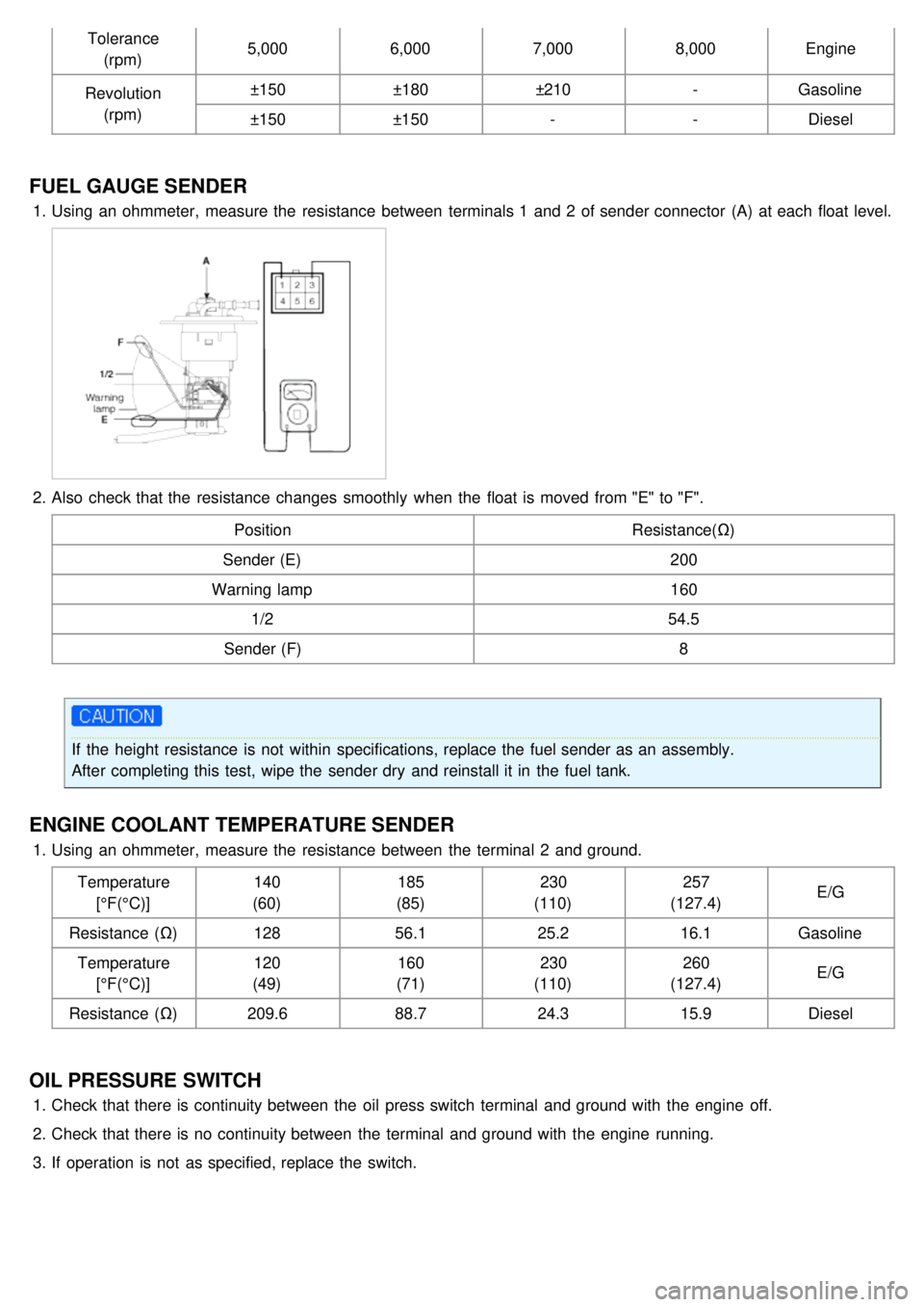
Tolerance(rpm) 5,000
6,0007,0008,000Engine
Revolution (rpm) ±150
±180±210 -Gasoline
±150 ±150 --Diesel
FUEL GAUGE SENDER
1.Using an ohmmeter, measure the resistance between terminals 1 and 2 of sender connector (A) at each float level.
2.Also check that the resistance changes smoothly when the float is moved from "E" to "F".
Position Resistance(Ω)
Sender (E) 200
Warning lamp 160
1/2 54.5
Sender (F) 8
If the height resistance is not within specifications, replace the fuel sender as an assembly.
After completing this test, wipe the sender dry and reinstall it in the fuel tank.
ENGINE COOLANT TEMPERATURE SENDER
1.Using an ohmmeter, measure the resistance between the terminal 2 and ground.
Temperature[°F(°C)] 140
(60) 185
(85) 230
(110) 257
(127.4) E/G
Resistance (Ω) 12856.1 25.216.1Gasoline
Temperature [°F(°C)] 120
(49) 160
(71) 230
(110) 260
(127.4) E/G
Resistance (Ω) 209.688.724.315.9Diesel
OIL PRESSURE SWITCH
1.Check that there is continuity between the oil press switch terminal and ground with the engine off.
2. Check that there is no continuity between the terminal and ground with the engine running.
3. If operation is not as specified, replace the switch.