2007 KIA CARNIVAL turn signal
[x] Cancel search: turn signalPage 1246 of 1575
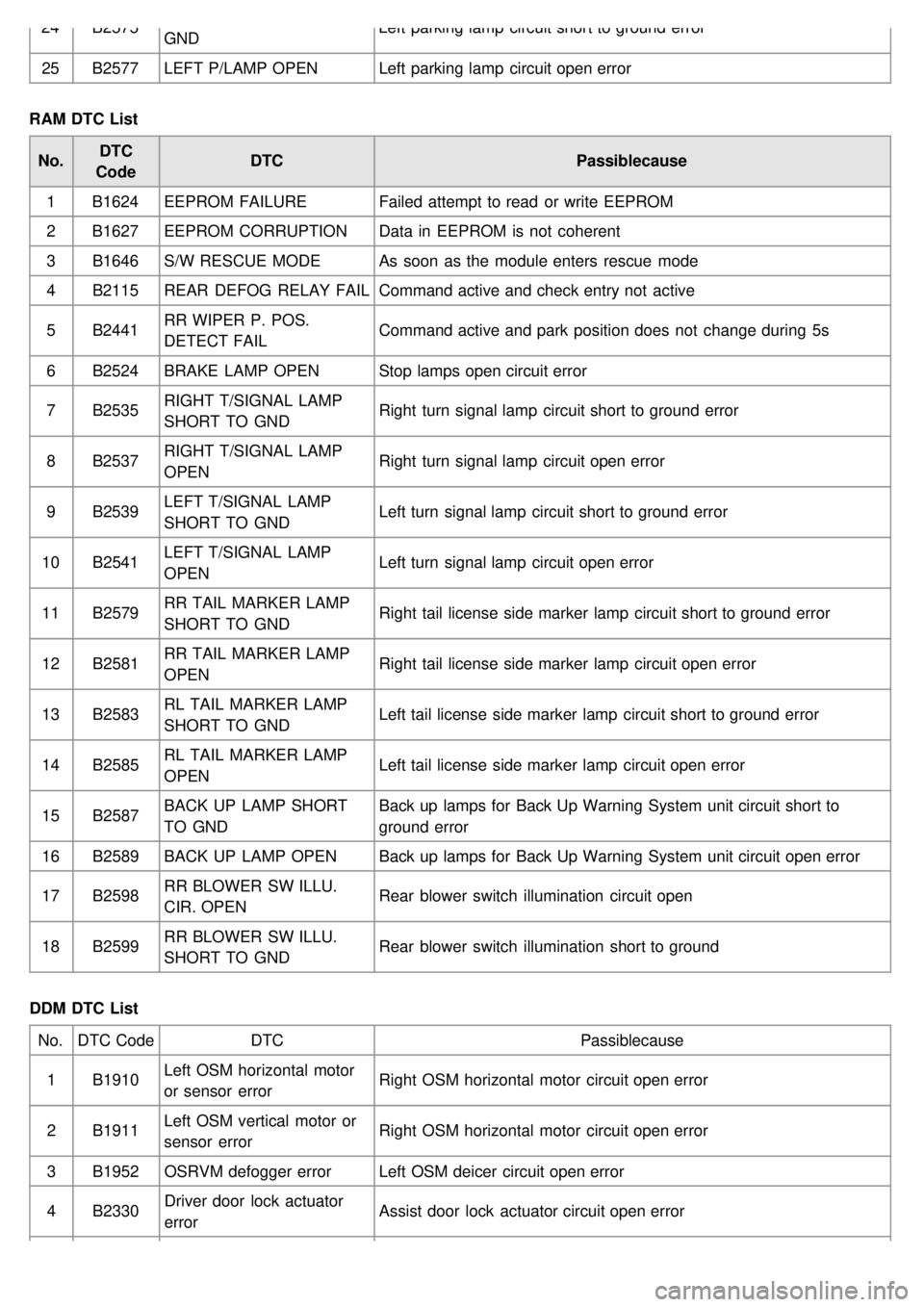
24B2575
GND Left parking lamp circuit short to ground error
25 B2577 LEFT P/LAMP OPEN Left parking lamp circuit open error
RAM DTC List No. DTC
Code DTC
Passiblecause
1 B1624 EEPROM FAILURE Failed attempt to read or write EEPROM
2 B1627 EEPROM CORRUPTION Data in EEPROM is not coherent
3 B1646 S/W RESCUE MODE As soon as the module enters rescue mode
4 B2115 REAR DEFOG RELAY FAIL Command active and check entry not active
5 B2441 RR WIPER P. POS.
DETECT FAIL Command active and park position does not change during 5s
6 B2524 BRAKE LAMP OPEN Stop lamps open circuit error
7 B2535 RIGHT T/SIGNAL LAMP
SHORT TO GND Right turn signal lamp circuit short to ground error
8 B2537 RIGHT T/SIGNAL LAMP
OPEN Right turn signal lamp circuit open error
9 B2539 LEFT T/SIGNAL LAMP
SHORT TO GND Left turn signal lamp circuit short to ground error
10 B2541 LEFT T/SIGNAL LAMP
OPEN Left turn signal lamp circuit open error
11 B2579 RR TAIL MARKER LAMP
SHORT TO GND Right tail license side marker lamp circuit short to ground error
12 B2581 RR TAIL MARKER LAMP
OPEN Right tail license side marker lamp circuit open error
13 B2583 RL TAIL MARKER LAMP
SHORT TO GND Left tail license side marker lamp circuit short to ground error
14 B2585 RL TAIL MARKER LAMP
OPEN Left tail license side marker lamp circuit open error
15 B2587 BACK UP LAMP SHORT
TO GND Back up lamps for Back Up Warning System unit circuit short to
ground error
16 B2589 BACK UP LAMP OPEN Back up lamps for Back Up Warning System unit circuit open error
17 B2598 RR BLOWER SW ILLU.
CIR. OPEN Rear blower switch illumination circuit open
18 B2599 RR BLOWER SW ILLU.
SHORT TO GND Rear blower switch illumination short to ground
DDM DTC List No. DTC Code DTC Passiblecause
1 B1910 Left OSM horizontal motor
or sensor error Right OSM horizontal motor circuit open error
2 B1911 Left OSM vertical motor or
sensor error Right OSM horizontal motor circuit open error
3 B1952 OSRVM defogger error Left OSM deicer circuit open error
4 B2330 Driver door lock actuator
error Assist door lock actuator circuit open error
Page 1248 of 1575
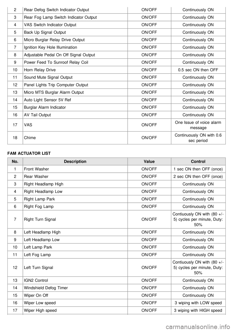
2Rear Defog Switch Indicator Output ON/OFFContinuously ON
3 Rear Fog Lamp Switch Indicator Output ON/OFFContinuously ON
4 VAS Switch Indicator Output ON/OFFContinuously ON
5 Back Up Signal Output ON/OFFContinuously ON
6 Micro Burglar Relay Drive Output ON/OFFContinuously ON
7 Ignition Key Hole Illumination ON/OFFContinuously ON
8 Adjustable Pedal On Off Signal Output ON/OFFContinuously ON
9 Power Feed To Sunroof Relay Coil ON/OFFContinuously ON
10 Horn Relay Drive ON/OFF0.5 sec ON then OFF
11 Sound Mute Signal Output ON/OFFContinuously ON
12 Panel Lights Trip Computer Output ON/OFFContinuously ON
13 Micro MTS Burglar Alarm Output ON/OFFContinuously ON
14 Auto Light Sensor 5V Ref ON/OFFContinuously ON
15 Burglar Alarm Indicator ON/OFFContinuously ON
16 AV Tail Output ON/OFFContinuously ON
17 VAS ON/OFFOne Issue of voice alarm
message
18 Chime ON/OFFContinuously ON with 0.6
sec period
FAM ACTUATOR LIST No. Description ValueControl
1 Front Washer ON/OFF1 sec ON then OFF (once)
2 Rear Washer ON/OFF2 sec ON then OFF (once)
3 Right Headlamp High ON/OFFContinuously ON
4 Right Headlamp Low ON/OFFContinuously ON
5 Right Lamp Park ON/OFFContinuously ON
6 Right Fog Lamp ON/OFFContinuously ON
7 Right Turn Signal ON/OFFContiuously ON with (80 +/ -
5) cycles per minute, Duty: 50%
8 Left Headlamp High ON/OFFContinuously ON
9 Left Headlamp Low ON/OFFContinuously ON
10 Left Lamp Park ON/OFFContinuously ON
11 Left Fog Lamp ON/OFFContinuously ON
12 Left Turn Signal ON/OFFContiuously ON with (80 +/ -
5) cycles per minute, Duty: 50%
13 IGN2 Control ON/OFFContinuously ON
14 Windshield Defog Timer ON/OFFContinuously ON
15 Wiper On Off ON/OFFContinuously ON
16 Wiper Low speed ON/OFF3 wiping with LOW speed
17 Wiper High speed ON/OFF3 wiping with HIGH speed
Page 1249 of 1575
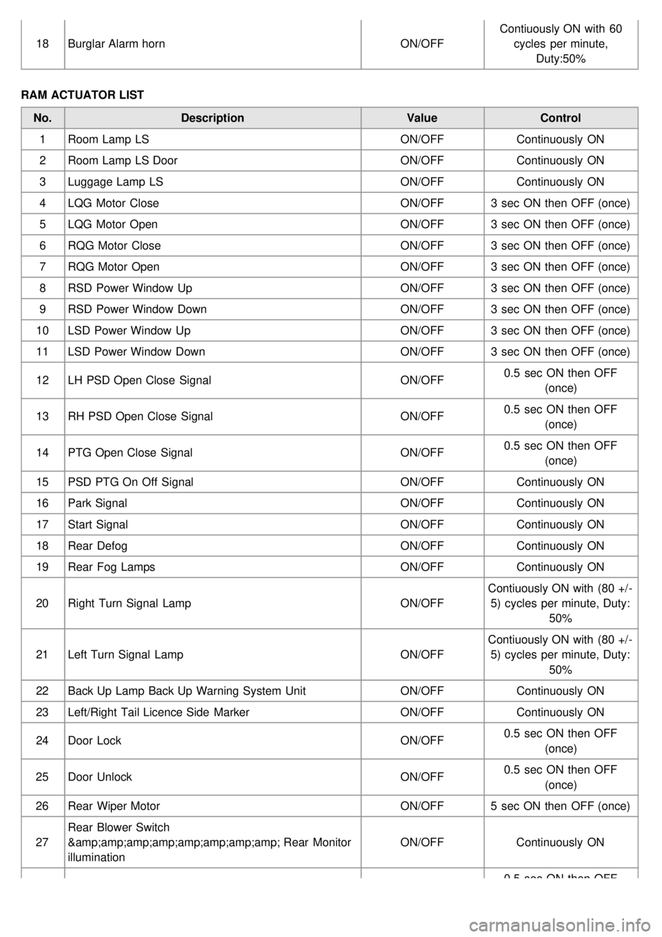
18Burglar Alarm horn ON/OFFContiuously ON with 60
cycles per minute, Duty:50%
RAM ACTUATOR LIST No. Description ValueControl
1 Room Lamp LS ON/OFFContinuously ON
2 Room Lamp LS Door ON/OFFContinuously ON
3 Luggage Lamp LS ON/OFFContinuously ON
4 LQG Motor Close ON/OFF3 sec ON then OFF (once)
5 LQG Motor Open ON/OFF3 sec ON then OFF (once)
6 RQG Motor Close ON/OFF3 sec ON then OFF (once)
7 RQG Motor Open ON/OFF3 sec ON then OFF (once)
8 RSD Power Window Up ON/OFF3 sec ON then OFF (once)
9 RSD Power Window Down ON/OFF3 sec ON then OFF (once)
10 LSD Power Window Up ON/OFF3 sec ON then OFF (once)
11 LSD Power Window Down ON/OFF3 sec ON then OFF (once)
12 LH PSD Open Close Signal ON/OFF0.5 sec ON then OFF
(once)
13 RH PSD Open Close Signal ON/OFF0.5 sec ON then OFF
(once)
14 PTG Open Close Signal ON/OFF0.5 sec ON then OFF
(once)
15 PSD PTG On Off Signal ON/OFFContinuously ON
16 Park Signal ON/OFFContinuously ON
17 Start Signal ON/OFFContinuously ON
18 Rear Defog ON/OFFContinuously ON
19 Rear Fog Lamps ON/OFFContinuously ON
20 Right Turn Signal Lamp ON/OFFContiuously ON with (80 +/ -
5) cycles per minute, Duty: 50%
21 Left Turn Signal Lamp ON/OFFContiuously ON with (80 +/ -
5) cycles per minute, Duty: 50%
22 Back Up Lamp Back Up Warning System Unit ON/OFFContinuously ON
23 Left/Right Tail Licence Side Marker ON/OFFContinuously ON
24 Door Lock ON/OFF0.5 sec ON then OFF
(once)
25 Door Unlock ON/OFF0.5 sec ON then OFF
(once)
26 Rear Wiper Motor ON/OFF5 sec ON then OFF (once)
27 Rear Blower Switch
& Rear Monitor
illumination ON/OFF
Continuously ON
0.5 sec ON then OFF
Page 1259 of 1575
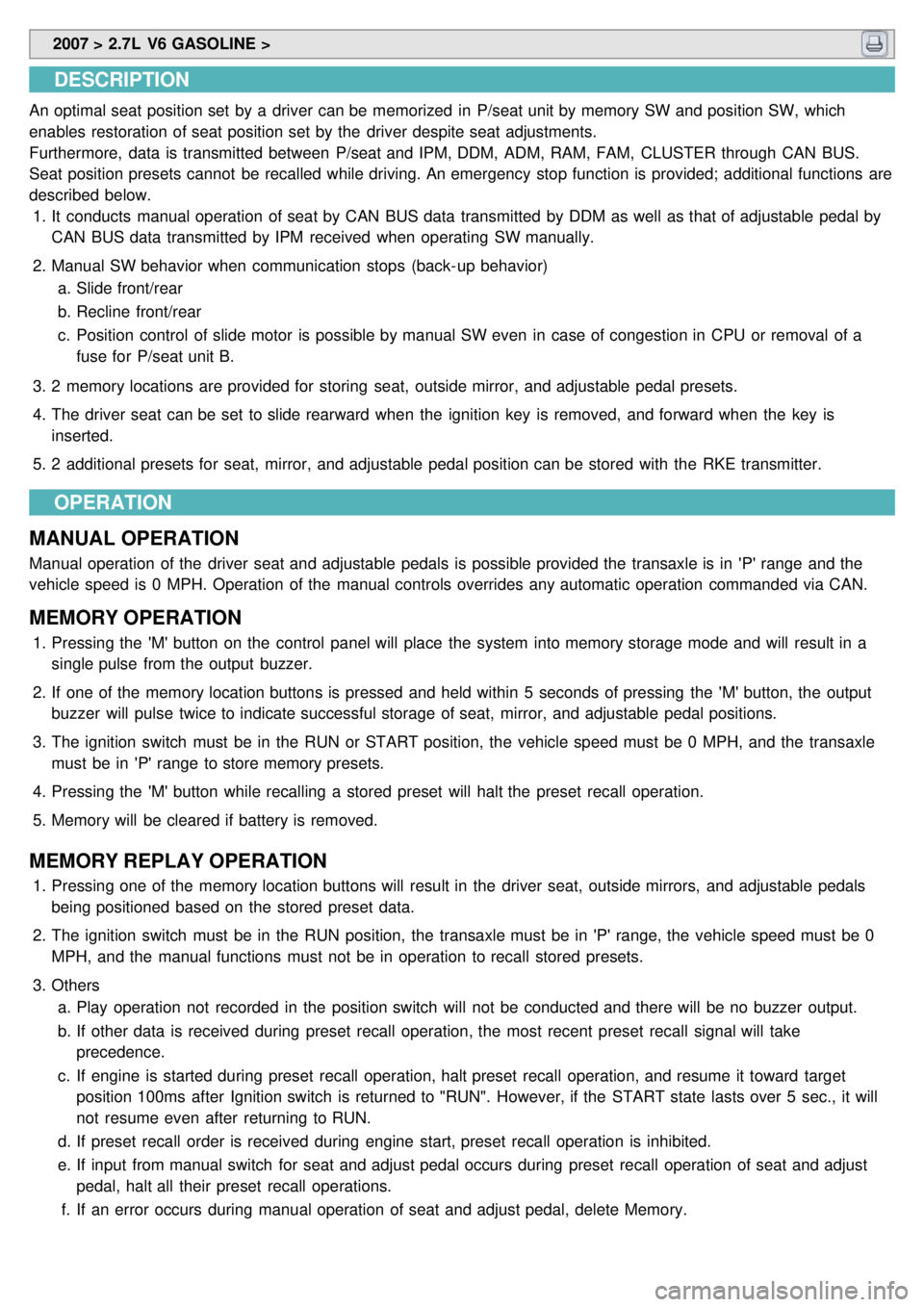
2007 > 2.7L V6 GASOLINE >
DESCRIPTION
An optimal seat position set by a driver can be memorized in P/seat unit by memory SW and position SW, which
enables restoration of seat position set by the driver despite seat adjustments.
Furthermore, data is transmitted between P/seat and IPM, DDM, ADM, RAM, FAM, CLUSTER through CAN BUS.
Seat position presets cannot be recalled while driving. An emergency stop function is provided; additional functions are
described below.
1. It conducts manual operation of seat by CAN BUS data transmitted by DDM as well as that of adjustable pedal by
CAN BUS data transmitted by IPM received when operating SW manually.
2. Manual SW behavior when communication stops (back- up behavior)
a. Slide front/rear
b. Recline front/rear
c. Position control of slide motor is possible by manual SW even in case of congestion in CPU or removal of a
fuse for P/seat unit B.
3. 2 memory locations are provided for storing seat, outside mirror, and adjustable pedal presets.
4. The driver seat can be set to slide rearward when the ignition key is removed, and forward when the key is
inserted.
5. 2 additional presets for seat, mirror, and adjustable pedal position can be stored with the RKE transmitter.
OPERATION
MANUAL OPERATION
Manual operation of the driver seat and adjustable pedals is possible provided the transaxle is in 'P' range and the
vehicle speed is 0 MPH. Operation of the manual controls overrides any automatic operation commanded via CAN.
MEMORY OPERATION
1. Pressing the 'M' button on the control panel will place the system into memory storage mode and will result in a
single pulse from the output buzzer.
2. If one of the memory location buttons is pressed and held within 5 seconds of pressing the 'M' button, the output
buzzer will pulse twice to indicate successful storage of seat, mirror, and adjustable pedal positions.
3. The ignition switch must be in the RUN or START position, the vehicle speed must be 0 MPH, and the transaxle
must be in 'P' range to store memory presets.
4. Pressing the 'M' button while recalling a stored preset will halt the preset recall operation.
5. Memory will be cleared if battery is removed.
MEMORY REPLAY OPERATION
1.Pressing one of the memory location buttons will result in the driver seat, outside mirrors, and adjustable pedals
being positioned based on the stored preset data.
2. The ignition switch must be in the RUN position, the transaxle must be in 'P' range, the vehicle speed must be 0
MPH, and the manual functions must not be in operation to recall stored presets.
3. Others
a. Play operation not recorded in the position switch will not be conducted and there will be no buzzer output.
b. If other data is received during preset recall operation, the most recent preset recall signal will take
precedence.
c. If engine is started during preset recall operation, halt preset recall operation, and resume it toward target
position 100ms after Ignition switch is returned to "RUN". However, if the START state lasts over 5 sec., it will
not resume even after returning to RUN.
d. If preset recall order is received during engine start, preset recall operation is inhibited.
e. If input from manual switch for seat and adjust pedal occurs during preset recall operation of seat and adjust
pedal, halt all their preset recall operations.
f. If an error occurs during manual operation of seat and adjust pedal, delete Memory.
Page 1262 of 1575
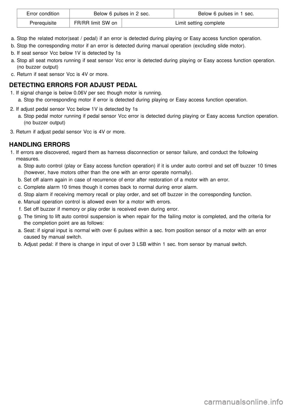
Error conditionBelow 6 pulses in 2 sec. Below 6 pulses in 1 sec.
Prerequisite FR/RR limit SW on Limit setting complete
a. Stop the related motor(seat / pedal) if an error is detected during playing or Easy access function operation.
b. Stop the corresponding motor if an error is detected during manual operation (excluding slide motor).
b. If seat sensor Vcc below 1V is detected by 1s
a. Stop all seat motors running if seat sensor Vcc error is detected during playing or Easy access function operation.
(no buzzer output)
c. Return if seat sensor Vcc is 4V or more.
DETECTING ERRORS FOR ADJUST PEDAL
1.If signal change is below 0.06V per sec though motor is running.
a. Stop the corresponding motor if error is detected during playing or Easy access function operation.
2. If adjust pedal sensor Vcc below 1V is detected by 1s
a. Stop pedal motor running if pedal sensor Vcc error is detected during playing or Easy access function operation.
(no buzzer output)
3. Return if adjust pedal sensor Vcc is 4V or more.
HANDLING ERRORS
1.If errors are discovered, regard them as harness disconnection or sensor failure, and conduct the following
measures.
a. Stop auto control (play or Easy access function operation) if it is under auto control and set off buzzer 10 times
(however, have motors other than the one with an error operate normally).
b. Set off alarm again in case of recurrence of error after restoration of a motor with an error.
c. Complete alarm 10 times though it comes back to normal during error alarm.
d. Stop alarm if receiving memory recall or play order, and set off buzzer in the corresponding function.
e. Manual operation control is allowed even for a motor with errors.
f. Set off buzzer if memory or play order is received even during error.
g. The timing to lift auto control suspension is when repair for the failing motor is completed, and the criteria for
the completion point are as follows:
a. Seat: if signal input is normal with over 6 pulses within a sec. from position sensor of a motor with an error
caused by manual switch.
b. Adjust pedal: if there is change in input of over 3 LSB within 1 sec. from sensor by manual switch.
Page 1434 of 1575
2007 > 2.7L V6 GASOLINE >
DESCRIPTION
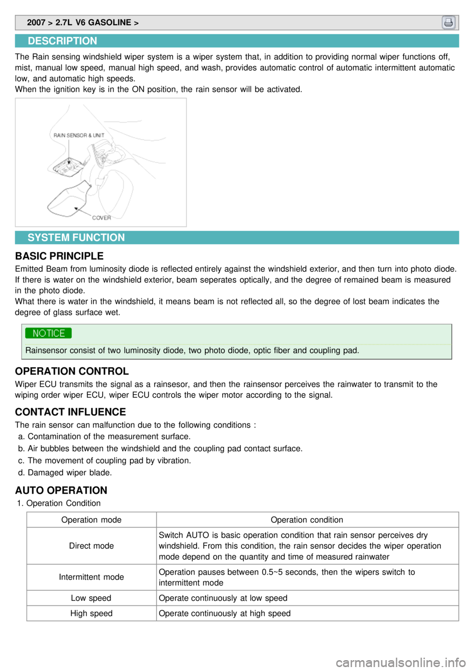
The Rain sensing windshield wiper system is a wiper system that, in addition to providing normal wiper functions off,
mist, manual low speed, manual high speed, and wash, provides automatic control of automatic intermittent automatic
low, and automatic high speeds.
When the ignition key is in the ON position, the rain sensor will be activated.
SYSTEM FUNCTION
BASIC PRINCIPLE
Emitted Beam from luminosity diode is reflected entirely against the windshield exterior, and then turn into photo diode.
If there is water on the windshield exterior, beam seperates optically, and the degree of remained beam is measured
in the photo diode.
What there is water in the windshield, it means beam is not reflected all, so the degree of lost beam indicates the
degree of glass surface wet.
Rainsensor consist of two luminosity diode, two photo diode, optic fiber and coupling pad.
OPERATION CONTROL
Wiper ECU transmits the signal as a rainsesor, and then the rainsensor perceives the rainwater to transmit to the
wiping order wiper ECU, wiper ECU controls the wiper motor according to the signal.
CONTACT INFLUENCE
The rain sensor can malfunction due to the following conditions : a. Contamination of the measurement surface.
b. Air bubbles between the windshield and the coupling pad contact surface.
c. The movement of coupling pad by vibration.
d. Damaged wiper blade.
AUTO OPERATION
1.Operation Condition
Operation mode Operation condition
Direct mode Switch AUTO is basic operation condition that rain sensor perceives dry
windshield. From this condition, the rain sensor decides the wiper operation
mode depend on the quantity and time of measured rainwater
Intermittent mode Operation pauses between 0.5~5 seconds, then the wipers switch to
intermittent mode
Low speed Operate continuously at low speed
High speed Operate continuously at high speed
Page 1435 of 1575
2.Safety Function
a. When there is an ice in the sensing field, the rain sensor cannot recognize the correct working condition.
Do not operate the rain sensing wipers unless the windshield is completely clear of ice and snow.
b. Glass damage : rain sensor cannot perceive the damaged windshield within the sensing field.
c. The rain senson will not operate properly if detached from the windsheld.
d. If the wiper ECU does not transmit any effective data in 5 seconds, the rain sensor turns off LED.
e. If the intermittent wiper signal is interrupted for >2 sec, the wipers are moved to the parking position.
f. If a rain sensor signal communication error lasts for > 5sec, the wipers are moved into the parking position.
g. If the rain sensor transmits an error to the wiper ECU, the wiper ECU stops the AUTO function after 4.5
seconds.
Page 1467 of 1575
2007 > 2.7L V6 GASOLINE >
SPECIFICATION
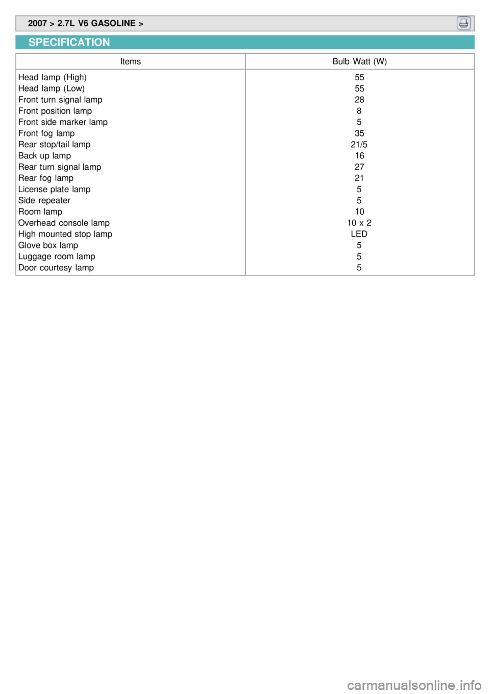
Items Bulb Watt (W)
Head lamp (High)
Head lamp (Low)
Front turn signal lamp
Front position lamp
Front side marker lamp
Front fog lamp
Rear stop/tail lamp
Back up lamp
Rear turn signal lamp
Rear fog lamp
License plate lamp
Side repeater
Room lamp
Overhead console lamp
High mounted stop lamp
Glove box lamp
Luggage room lamp
Door courtesy lamp 55
55
28
8
5
35
21/5 16
27
215
5
10
10 x 2 LED 5
5
5