2007 KIA CARNIVAL key battery
[x] Cancel search: key batteryPage 1218 of 1575
b.When the multifunction switch is not in postion headlamps turned on or autolight
c. 20 mn after the driver door is open
d. 20mn after IGN leaves the positions RUN to ACC or OFF
e. If IPM receives RKE "LOCK" command two times
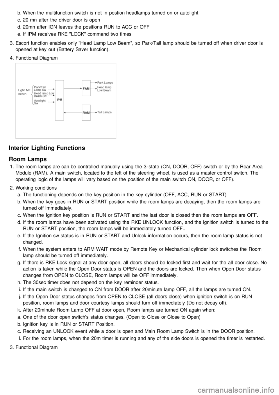
3. Escort function enables only "Head Lamp Low Beam", so Park/Tail lamp should be turned off when driver door is
opened at key out (Battery Saver function).
4. Functional Diagram
Interior Lighting Functions
Room Lamps
1.The room lamps are can be controlled manually using the 3 - state (ON, DOOR, OFF) switch or by the Rear Area
Module (RAM). A main switch, located to the left of the steering wheel, is used as a master control switch. The
operating logic of the lamps will vary based on the position of the main switch ON, DOOR, or OFF).
2. Working conditions
a. The functioning depends on the key position in the key cylinder (OFF, ACC, RUN or START)
b. When the key goes in RUN or START position while the room lamps are decaying, then the room lamps are
turned off immediately.
c. When the Ignition key position is RUN or START and the last door is closed then the room lamps are OFF.
d. If the room lamps have been activated using the RKE UNLOCK function, and the ignition switch is turned to the
RUN or START position, the room lamps will be immediately turned OFF..
e. If the Ignition sw status is in RUN or START and Unlock information occurs, then the room lamp status is not
changed.
f. When the system enters to ARM WAIT mode by Remote Key or Mechanical cylinder lock switches the Room
lamp should be turned off immediately.
g. If there is RKE Lock signal at any door open, all doors should be locked first and wait for the all door close. No
action is taken while the Open Door status is OPEN and the doors are locked. Then when Open Door status
changes from OPEN to CLOSE, Room lamps will be OFF immediately.
h. The 30sec timer does not depend on the key reminder status.
i. If the main switch is changed to ON from DOOR after 20minute lamp OFF, all the lamps are turned ON.
j. If the Open Door status changes from OPEN to CLOSE (all doors close) when ignition switch is on RUN
position, room lamps and door courtesy lamps should turn off immediately (Do not decay off).
k. After 20minute Room Lamp OFF at door open, Room lamps are turned ON again when:
a. One of the door open switch's status changes. (Open to Close or Close to Open)
b. Ignition key is in RUN or START Position.
c. Receiving an UNLOCK event while a door is open and Main Room Lamp Switch is in the DOOR position.
l. For the room lamps, when the 20m timer is running and any of the side doors is opened the timer is restarted.
3. Functional Diagram
Page 1236 of 1575
Battery Removal
a.If the battery is removed with the system in the ARM state, the system will be placed into the ARM state upon
battery reconnect.
b. The ALARM state will be re- activated if the battery is disconnected, then reconnected, with the system in an
ALARM state.
c. If the battery is disconnected and reconnected with the system in AFTER ALARM state, the alarm will be re-
activated.
d. The system will enter DISARM mode if the battery is disconnected during the ALARM WAIT state.
Panic
a.If RKE PANIC signal is received, Siren output and hazard lamp operate for 27 seconds and the system return to
the previous state as soon as the PANIC function finishes.
b. The PANIC function will be stopped if any RKE signal is received during PANIC activation..
c. If Key reminder switch is ON during PANIC function is operating, PANIC is stopped immediately.
d. If the system goes to ALARM mode during PANIC function is operating, PANIC is stopped immediately and then
ALARM function should be activated.
e. During ALARM state;
If RKE PANIC signal is received, ALARM mode is maintained and PANIC function should be ignored. ALARM has
higher priority than PANIC function.
f. During AFTER_ALARM state;
If RKE PANIC signal is received, AFTR_ALARM mode is maintained and PANIC function should be activated.
Safe & Rescue Mode
The goal of those modes is to be able to cope with failures that may happen on some of the most critical
functionalities (for the driver security) of the system.
Safe Mode
The safe mode is entered in case of system problems such as:
a. Incoherent inputs on monitored signals. In this case, safe mode is the debouncing time before the inputs are
considered INVALID. Note that today, we have no way to detect if the rain/light sensor is in working operation or
not. It means that a driver action will be required in case of failure of this sensor;
b. Loss of the CAN frame containing the monitored signal:
c. Loss of the CAN network: CAN goes to BUS OFF state, safe mode is the time necessary for detecting the BUS
OFF state.
In all cases, the action in safe mode is to maintain the previous state of the system (for lighting and wiping). The list of
monitored signals is the same as in rescue mode
Exiting Safe Mode
The software safe mode is exited and the module goes back to the normal mode when: a. On IPM, hardware inputs return to a coherent state;
b. The lost CAN signal comes back while timeout has not elapsed;
c. The CAN network returns to a normal state without reaching BUS OFF state.
Software safe mode is also exited when the software rescue mode is entered (problem does not disappear).
Hardware safe mode is exited and the module goes back to normal mode if the internal problem disappears (watchdog
is properly triggered again). If the problem stays, hardware safe mode is exited to enter hardware rescue mode.
Rescue Modes
The rescue mode consists in activating some safety functions when IGN2 = ON: a. Switch on the low beams (FAM), park lamps (FAM), tail lamps (RAM) and cluster backlighting (IPM);
b. Unlock of all the doors when the rescue mode is entered with IGN2 = ON
c. Front wipers do not need to be turned on by software in rescue mode because wipers can be turned on by
manually setting the MF switch to low speed. The FAM software must keep the same state as before entering the
rescue mode.
d. When IGN2 = OFF, low beams, park/tail lamps and cluster backlighting are turned off.
Entering Rescue Modes
Page 1251 of 1575
No.Description ValueControl
1 Power Seat Slide Forward Motor ON/OFFContinuously ON
2 Power Seat Slide Backward Motor ON/OFFContinuously ON
3 Power Seat FR Height Up Motor ON/OFFContinuously ON
4 Power Seat FR Height Down Motor ON/OFFContinuously ON
5 Power Seat RR Height Up Motor ON/OFFContinuously ON
6 Power Seat RR Height Down Motor ON/OFFContinuously ON
7 Power Seat Recline Forward Motor ON/OFFContinuously ON
8 Power Seat Recline Backward Motor ON/OFFContinuously ON
9 Pedal Forward Motor ON/OFFContinuously ON
10 Pedal Backward Motor ON/OFFContinuously ON
REPLACEMENT
IPM (In-Panel Module)
1. Disconnect the negative ( - ) battery terminal.
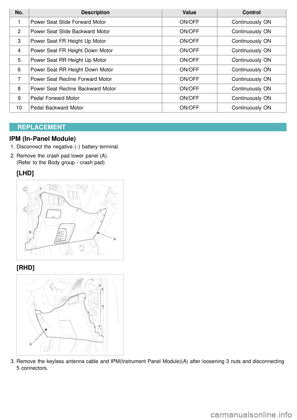
2. Remove the crash pad lower panel (A).
(Refer to the Body group - crash pad)
[LHD]
[RHD]
3.Remove the keyless antenna cable and IPM(Instrument Panel Module)(A) after loosening 3 nuts and disconnecting
5 connectors.
Page 1259 of 1575
2007 > 2.7L V6 GASOLINE >
DESCRIPTION
An optimal seat position set by a driver can be memorized in P/seat unit by memory SW and position SW, which
enables restoration of seat position set by the driver despite seat adjustments.
Furthermore, data is transmitted between P/seat and IPM, DDM, ADM, RAM, FAM, CLUSTER through CAN BUS.
Seat position presets cannot be recalled while driving. An emergency stop function is provided; additional functions are
described below.
1. It conducts manual operation of seat by CAN BUS data transmitted by DDM as well as that of adjustable pedal by
CAN BUS data transmitted by IPM received when operating SW manually.
2. Manual SW behavior when communication stops (back- up behavior)
a. Slide front/rear
b. Recline front/rear
c. Position control of slide motor is possible by manual SW even in case of congestion in CPU or removal of a
fuse for P/seat unit B.
3. 2 memory locations are provided for storing seat, outside mirror, and adjustable pedal presets.
4. The driver seat can be set to slide rearward when the ignition key is removed, and forward when the key is
inserted.
5. 2 additional presets for seat, mirror, and adjustable pedal position can be stored with the RKE transmitter.
OPERATION
MANUAL OPERATION
Manual operation of the driver seat and adjustable pedals is possible provided the transaxle is in 'P' range and the
vehicle speed is 0 MPH. Operation of the manual controls overrides any automatic operation commanded via CAN.
MEMORY OPERATION
1. Pressing the 'M' button on the control panel will place the system into memory storage mode and will result in a
single pulse from the output buzzer.
2. If one of the memory location buttons is pressed and held within 5 seconds of pressing the 'M' button, the output
buzzer will pulse twice to indicate successful storage of seat, mirror, and adjustable pedal positions.
3. The ignition switch must be in the RUN or START position, the vehicle speed must be 0 MPH, and the transaxle
must be in 'P' range to store memory presets.
4. Pressing the 'M' button while recalling a stored preset will halt the preset recall operation.
5. Memory will be cleared if battery is removed.
MEMORY REPLAY OPERATION
1.Pressing one of the memory location buttons will result in the driver seat, outside mirrors, and adjustable pedals
being positioned based on the stored preset data.
2. The ignition switch must be in the RUN position, the transaxle must be in 'P' range, the vehicle speed must be 0
MPH, and the manual functions must not be in operation to recall stored presets.
3. Others
a. Play operation not recorded in the position switch will not be conducted and there will be no buzzer output.
b. If other data is received during preset recall operation, the most recent preset recall signal will take
precedence.
c. If engine is started during preset recall operation, halt preset recall operation, and resume it toward target
position 100ms after Ignition switch is returned to "RUN". However, if the START state lasts over 5 sec., it will
not resume even after returning to RUN.
d. If preset recall order is received during engine start, preset recall operation is inhibited.
e. If input from manual switch for seat and adjust pedal occurs during preset recall operation of seat and adjust
pedal, halt all their preset recall operations.
f. If an error occurs during manual operation of seat and adjust pedal, delete Memory.
Page 1332 of 1575
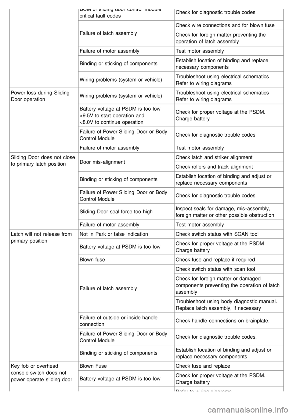
BCM or sliding door control module
critical fault codesCheck for diagnostic trouble codes
Failure of latch assembly Check wire connections and for blown fuse
Check for foreign matter preventing the
operation of latch assembly
Failure of motor assembly Test motor assembly
Binding or sticking of components Establish location of binding and replace
necessary components
Wiring problems (system or vehicle) Troubleshoot using electrical schematics
Refer to wiring diagrams
Power loss during Sliding
Door operation Wiring problems (system or vehicle)
Troubleshoot using electrical schematics
Refer to wiring diagrams
Battery voltage at PSDM is too low
<9.5V to start operation and
<8.0V to continue operation Check for proper voltage at the PSDM.
Charge battery
Failure of Power Sliding Door or Body
Control Module Check for diagnostic trouble codes
Failure of motor assembly Test motor assembly
Sliding Door does not close
to primary latch position Door mis - alignment Check latch and striker alignment
Check rollers and track alignment
Binding or sticking of components Establish location of binding and adjust or
replace necessary components
Failure of Power Sliding Door or Body
Control Module Check for diagnostic trouble codes
Sliding Door seal force too high Inspect seals for damage, mis - assembly,
foreign matter or other possible obstruction
Failure of motor assembly Test motor assembly
Latch will not release from
primary position Not in Park or false indication
Check switch status with SCAN tool
Battery voltage at PSDM is too low Check for proper voltage at the PSDM
Charge battery
Blown fuse Check fuse and replace if required
Failure of latch assembly Check switch status with scan tool
Check for foreign matter or damaged
components preventing the operation of latch
assembly
Troubleshoot using body diagnostic manual.
Replace latch assembly, if necessary
Failure of outside or inside handle
connection Check handle connections on brainplate.
Failure of Power Sliding Door or Body
Control Module Check for diagnostic trouble codes.
Binding or sticking of components Establish location of binding and adjust or
replace necessary components
Key fob or overhead
console switch does not
power operate sliding door Blown Fuse
Check fuse and replace
Battery voltage at PSDM is too low Check for proper voltage at the PSDM.
Charge battery
Refer to wiring diagrams
Page 1333 of 1575
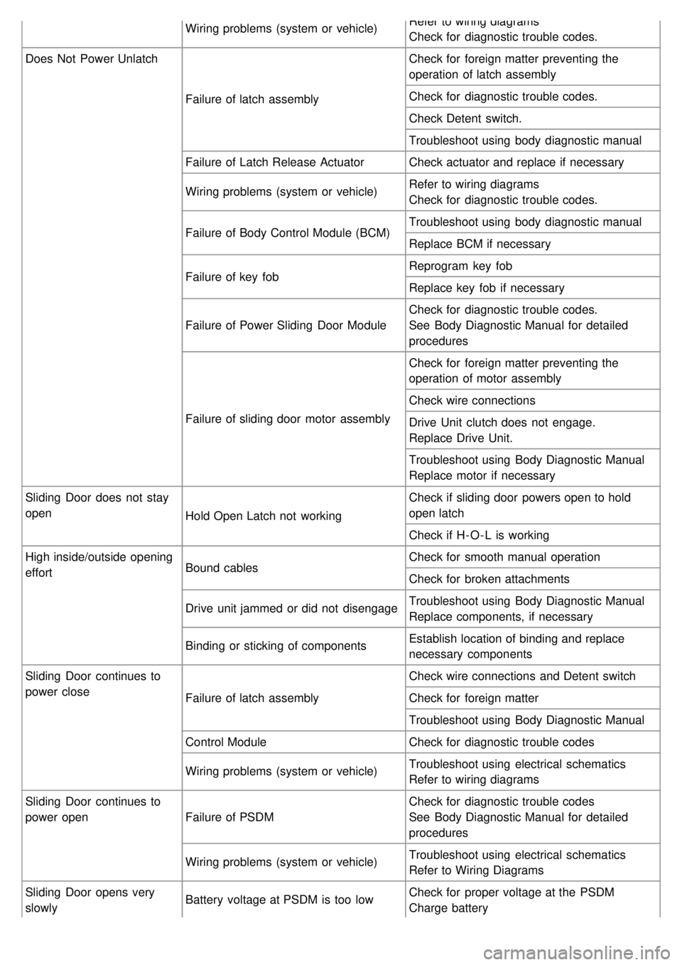
Wiring problems (system or vehicle)Refer to wiring diagrams
Check for diagnostic trouble codes.
Does Not Power Unlatch
Failure of latch assembly Check for foreign matter preventing the
operation of latch assembly
Check for diagnostic trouble codes.
Check Detent switch.
Troubleshoot using body diagnostic manual
Failure of Latch Release Actuator Check actuator and replace if necessary
Wiring problems (system or vehicle) Refer to wiring diagrams
Check for diagnostic trouble codes.
Failure of Body Control Module (BCM) Troubleshoot using body diagnostic manual
Replace BCM if necessary
Failure of key fob Reprogram key fob
Replace key fob if necessary
Failure of Power Sliding Door Module Check for diagnostic trouble codes.
See Body Diagnostic Manual for detailed
procedures
Failure of sliding door motor assembly Check for foreign matter preventing the
operation of motor assembly
Check wire connections
Drive Unit clutch does not engage.
Replace Drive Unit.
Troubleshoot using Body Diagnostic Manual
Replace motor if necessary
Sliding Door does not stay
open Hold Open Latch not working Check if sliding door powers open to hold
open latch
Check if H- O - L is working
High inside/outside opening
effort Bound cables Check for smooth manual operation
Check for broken attachments
Drive unit jammed or did not disengage Troubleshoot using Body Diagnostic Manual
Replace components, if necessary
Binding or sticking of components Establish location of binding and replace
necessary components
Sliding Door continues to
power close Failure of latch assembly Check wire connections and Detent switch
Check for foreign matter
Troubleshoot using Body Diagnostic Manual
Control Module Check for diagnostic trouble codes
Wiring problems (system or vehicle) Troubleshoot using electrical schematics
Refer to wiring diagrams
Sliding Door continues to
power open Failure of PSDM Check for diagnostic trouble codes
See Body Diagnostic Manual for detailed
procedures
Wiring problems (system or vehicle) Troubleshoot using electrical schematics
Refer to Wiring Diagrams
Sliding Door opens very
slowly Battery voltage at PSDM is too low
Check for proper voltage at the PSDM
Charge battery
Page 1373 of 1575
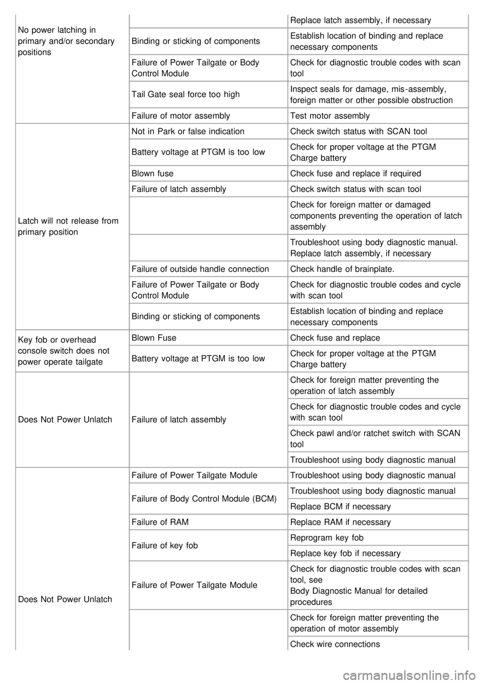
No power latching in
primary and/or secondary
positionsReplace latch assembly, if necessary
Binding or sticking of components Establish location of binding and replace
necessary components
Failure of Power Tailgate or Body
Control Module Check for diagnostic trouble codes with scan
tool
Tail Gate seal force too high Inspect seals for damage, mis - assembly,
foreign matter or other possible obstruction
Failure of motor assembly Test motor assembly
Latch will not release from
primary position Not in Park or false indication
Check switch status with SCAN tool
Battery voltage at PTGM is too low Check for proper voltage at the PTGM
Charge battery
Blown fuse Check fuse and replace if required
Failure of latch assembly Check switch status with scan tool
Check for foreign matter or damaged
components preventing the operation of latch
assembly
Troubleshoot using body diagnostic manual.
Replace latch assembly, if necessary
Failure of outside handle connection Check handle of brainplate.
Failure of Power Tailgate or Body
Control Module Check for diagnostic trouble codes and cycle
with scan tool
Binding or sticking of components Establish location of binding and replace
necessary components
Key fob or overhead
console switch does not
power operate tailgate Blown Fuse
Check fuse and replace
Battery voltage at PTGM is too low Check for proper voltage at the PTGM
Charge battery
Does Not Power Unlatch Failure of latch assembly Check for foreign matter preventing the
operation of latch assembly
Check for diagnostic trouble codes and cycle
with scan tool
Check pawl and/or ratchet switch with SCAN
tool
Troubleshoot using body diagnostic manual
Does Not Power Unlatch Failure of Power Tailgate Module
Troubleshoot using body diagnostic manual
Failure of Body Control Module (BCM) Troubleshoot using body diagnostic manual
Replace BCM if necessary
Failure of RAM Replace RAM if necessary
Failure of key fob Reprogram key fob
Replace key fob if necessary
Failure of Power Tailgate Module Check for diagnostic trouble codes with scan
tool, see
Body Diagnostic Manual for detailed
procedures
Check for foreign matter preventing the
operation of motor assembly
Check wire connections
Page 1387 of 1575
2007 > 2.7L V6 GASOLINE >
INPECTION
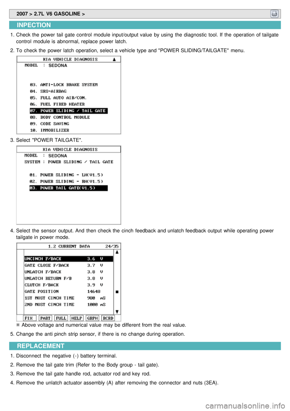
1.Check the power tail gate control module input/output value by using the diagnostic tool. If the operation of tailgate
control module is abnormal, replace power latch.
2. To check the power latch operation, select a vehicle type and "POWER SLIDING/TAILGATE" menu.
3.Select "POWER TAILGATE".
4.Select the sensor output. And then check the cinch feedback and unlatch feedback output while operating power
tailgate in power mode.
※ Above voltage and numerical value may be different from the real value.
5. Change the anti pinch strip sensor, if there is no change during operation.
REPLACEMENT
1.Disconnect the negative ( - ) battery terminal.
2. Remove the tail gate trim (Refer to the Body group - tail gate).
3. Remove the tail gate handle rod, actuator rod and key rod.
4. Remove the unlatch actuator assembly (A) after removing the connector and nuts (3EA).