Page 655 of 1575

Additional health and safety information may be obtained from the refrigerant and lubricant manufacturers.1. When an A/C System has been opened to the atmosphere, such as during installation or repair, it must be
evacuated using an R- 134a refrigerant Recovery/Recycling/Charging System. (If the system has been open for
several days, the receiver/dryer should be replaced, and the system should be evacuated for several hours.)
2. Connect an R- 134a refrigerant Recovery/Recycling/Charging System (A) to the high- pressure service port (B) and
the low- pressure service port (C) as shown, following the equipment manufacturer's instructions.
3.If the low- pressure does not reach more than 93.3 kPa (700 mmHg, 27.6 in.Hg) in 10 minutes, there is probably a
leak in the system. Partially charge the system, and check for leaks (see Leak Test.).
4. Remove the low pressure valve from the low- pressure service port.
SYSTEM CHARGING
Use only service equipment that is U.L - listed and is certified to meet the requirements of SAE J2210 to remove HFC-
134a(R- 134a) from the air conditioning system.
a.Air conditioning refrigerant or lubricant vapor can irritate your eyes, nose, or throat.
b. Be careful when connecting service equipment.
c. Do not breathe refrigerant or vapor.
If accidental system discharge occurs, ventilate work area before resuming service.
Additional health and safety information may be obtained from the refrigerant and lubricant manufacturers. 1. Connect an R- 134a refrigerant Recovery/Recycling/Charging System (A) to the high- pressure service port (B) as
shown, following the equipment manufacturer's instructions.
2.Add the same amount of new refrigerant oil to system that was removed during recovery. Use only specified
refrigerant oil. Charge the system with 28.21 ± 0.88 oz. (800 ± 25g) of R- 134a refrigerant. Do not overcharge the
system the compressor will be damaged.
REFRIGERANT LEAK TEST
Always conduct a leak test with an electronic leak detector whenever leakage or refrigerant is suspected and when
conducting service operations which are accompanied by disassembly or loosening or connection fittings.
Page 660 of 1575

2007 > 2.7L V6 GASOLINE >
REMOVAL
1.If the compressor is marginally operable, run the engine at idle speed, and let the air conditioning work for a few
minutes, then shut the engine off.
2. Disconnect the negative cable from the battery.
3. Recover the refrigerant with a recovery/charging station (Refer to HA - 8).
4. Loosen the drive belt (Refer to HA - 14).
5. Remove the bolts, then disconnect the suction line (A) and discharge line (B) from the compressor. Plug (C) or cap
the lines immediately after disconnecting them to avoid moisture and dust contamination.
6.Disconnect the compressor clutch connector (A), and then remove 4 mounting bolts and the compressor.
INSTALLATION
1.Make sure of the length of compressor mounting bolts.
2.Install in the reverse order of removal, and note these items.
a. If you're installing a new compressor, drain all the refrigerant oil from the removed compressor, and measure its
volume, Subtract the volume of drained oil from 120cc(4.20 oz.) the result is the amount of oil you should drain
Page 668 of 1575

2007 > 2.7L V6 GASOLINE >
INSPECTION
1.Check the condenser fins for clogging and damage. If clogged, clean them with water, and blow them with
compressed air. If bent, gently bend them using a screwdriver or pliers.
2. Check the condenser connections for leakage, and repair or replace it, if required.
REPLACEMENT
CONDENSER ASSEMBLY
1. Recover the refrigerant with a recovery/ recycling/ charging station (Refer to HA - 8).
2. Disconnect the negative ( - ) battery terminal.
3. Remove the radiator. (Refer to EM group)
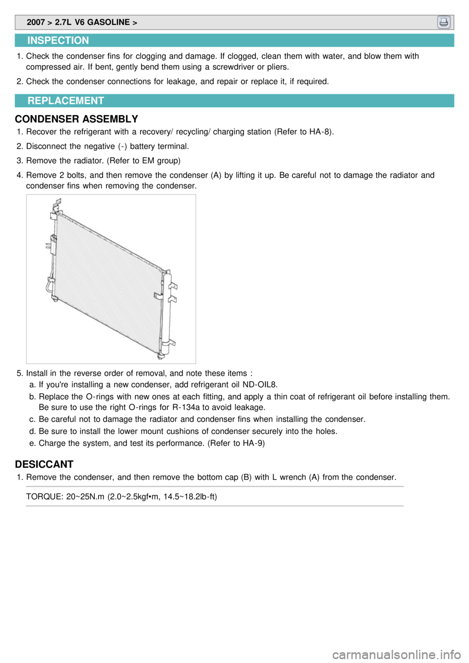
4. Remove 2 bolts, and then remove the condenser (A) by lifting it up. Be careful not to damage the radiator and
condenser fins when removing the condenser.
5.Install in the reverse order of removal, and note these items :
a. If you're installing a new condenser, add refrigerant oil ND- OIL8.
b. Replace the O - rings with new ones at each fitting, and apply a thin coat of refrigerant oil before installing them.
Be sure to use the right O - rings for R- 134a to avoid leakage.
c. Be careful not to damage the radiator and condenser fins when installing the condenser.
d. Be sure to install the lower mount cushions of condenser securely into the holes.
e. Charge the system, and test its performance. (Refer to HA - 9)
DESICCANT
1.Remove the condenser, and then remove the bottom cap (B) with L wrench (A) from the condenser.
TORQUE: 20~25N.m (2.0~2.5kgf•m, 14.5~18.2lb - ft)
Page 676 of 1575
2007 > 2.7L V6 GASOLINE >
INSPECTION
1.Measure the pressure of high pressure line by measuring voltage output between NO.1 and NO.2 terminals.
2.Inspect the voltage value whether it is sufficient to be regular value or not.
Vout = Vdd(0.025 * P + 0.1) [kgf/cm²G]
Vout = Vdd(0.001758 * P + 0.074162) [PSIA]
3. If the measured voltage value is not specification, replace the A/C pressure transducer.
REPLACEMENT
1.Disconnect the negative ( - ) battery terminal.
2. Recover the refrigerant with a recovery/charging station.
3. Disconnect A/C pressure transducer connector (3P) (A).
Page 713 of 1575

2007 > 2.7L V6 GASOLINE >
REPLACEMENT
1.Disconnect the negative ( - ) battery terminal.
2. Recover the refrigerant with a recovery/ recycling/ charging station. (Refer to HA - 8)
3. When the engine is cool, drain the engine coolant from the radiator.
4. Remove the bolts (A) and the expansion valve (B) from the evaporator core.
Plug or cap the lines immediately after disconnecting them to avoid moisture and dust contamination.
5.Disconnect the inlet (A) and outlet (B) heater hoses from the heater unit.
Engine coolant will run out when the hoses are disconnected; drain it into a clean drip pan. Be sure not to let
coolant spill on electrical parts or painted surfaces. If any coolant spills, rinse it off immediately.
6. Remove the crash pad (Refer to BD group).
7. Remove the cowl cross bar assembly. (Refer to BD group)
8. Disconnect the connectors from the temperature control actuator, the mode control actuator and the evaporator
temperature sensor.
9. Remove the heater & blower unit after loosening 3 mounting bolts.
Page 743 of 1575
2007 > 2.7L V6 GASOLINE >
REPLACEMENT
1.Disconnect the negative(- ) battery terminal.
2. Recover the refrigerant with a recover/ recycling/ charging station.
3. When the engine is cool, drain the engine coolant from the radiator.
4. Remove luggage side trim(Refer to BD - ).
5. Loosen the refrigerant line mounting bolts, and then remove the rear refrigerant line(A).
6.Remove the heater hose(A), drain hose(B).
7.Remove the rear heater main connector(A).
8.Loosen the rear heater mounting nuts, and then remove the rear heater unit(A).
Page 1227 of 1575
Easy Access
1.Description
The easy access function permits automatic rearward movement of the driver seat when the key is removed from
the cylinder. Automatic forward movement of the driver seat will take place when the key is inserted into the
cylinder. This function will be enabled on IMS equipped vehicles when the AUTO button is pressed.
Inhibit Switch should be in P- Position for the Easy Access operation.
2. Functional Diagram
Driver Information
Cluster Indicators
1.The instument cluster indicators listed below are controlled by the In- Panel Module (IPM), Front Area Module
(FAM), or Rear Area Module (RAM) as applicable.
These indicators are:
a. Gearbox status
b. Oil pressure
c. Sediment fuel filter
d. Vacuum
e. Brake fluid
f. Washer fluid
g. Seat belt
h. Park brake
i. Charging voltage
j. Turn indicators
k. High beam
l. Front fog
m. Doors open
n. Tailgate open
o. Stop lamp failure front and rear
2. Functional Diagram
Page 1229 of 1575

switch, the status of the ABS EBD warning, the status of the brake fluid sensor and the speed of the vehicle.
The IPM sends the park brake indicator control on the CAN network.
The indicator is lighted if the vacuum switch or ABS EBD warning are on or brake fluid sensor is low or park brake
switch is on.
If the speed of the vehicle is over 10 km/h and ignition switch is on the status RUN the park brake indicator control is
blinking at 50% duty in 0.6 second if Parking Brake switch Input is active. In this case Vacuum switch, ABS EBD
warning and Brake Fluid sensor are ignored.
The park brake indicator is blinking on the same time that the chime is ringing. If a CAN signal among Vacuum switch,
EBD warning or Brake Fluid Sens switch is INVALID, out of range or not received this CAN signal is considered to be
OFF.
If VehicleSpeed CAN signal is INVALID or not received, it is considered to be 0 kph.
Charging Voltage Control
The IPM receives on analog input the voltage of generator and sends a warning.
When the voltage of generator L pass strictly above 10V, the state of the CAN variable.
Turn Indicators Status
The status of the turn indicators are sent on the CAN network when the CAN network is available.
High Beam Status
The status of the high beam is sent on the CAN network when the CAN network is available.
Front Fog Lamp Status
The status of the front fog lamp (lightning and state of the bulbs) is sent on the CAN network when the CAN network
is available.
Doors Open Warning
The RAM receives on digital input the status of the driver door open switch and sends it on the CAN network.
The RAM receives on digital input the status of the passenger door open switch and sends it on the CAN network.
The RAM receives on digital input the status of the left sliding door open switch and sends it on the CAN network.
The RAM receives on digital input the status of the right sliding door open switch and sends it on the CAN network.
When vehicle speed is under 10 kph, with ignition key not inserted and any door OPEN, DoorsOpenWngCtrl stays ON
for 20 min and then is turned OFF.
Tailgate Open Switch Status
When vehicle speed is under 10 kph, ignition key is inserted and Tailgate open switch is OPEN, Tailgate Open
warning stays ON forever (IPM can enter sleep mode).
When vehicle speed is under 10 kph, with ignition key not inserted and lgate open switch is OPEN, Tailgate Open
warning stays ON for 20 min and then is turned OFF.
Chime Control
1.The chime warns the driver that a problem is occurred.
These warning are:
a. Seat belt
b. Parking on
c. Over speed
d. Key reminder
e. Light Warning
f. Doors Open
g. Tailgate open warning
2. Chime sound priority:
a. 1st : Seatbelt warning
b. 2nd : Overspeed warning
c. 3rd : Door open warning
d. 4th : T/Gate open warning
e. 5th : Key operated warning
f. 6th : Parking Brake warning