Page 1212 of 1575
Functions
Exterior Lighting Functions
The exterior lighting function has to provide the lighting and signalling of the vehicle; it monitors different available
lights in front or at the back of the vehicle: a. Park and Tail lamps (with Side marker lamps),
b. License plate lamps,
c. Head lamps Low Beam,
d. Head lamps High Beam,
e. Front and Rear fog lamps (with the Rear fog lamp switch indicator),
f. Stop lamps,
g. Backup lamps,
h. Turn signal and side repeater lamps.
Park/tail Lamps Function
1.Necessary conditions to switch ON :
a. By putting the Head lamp switch in position 'Park and Tail lamp' or 'Head lamp Low Beam' or Auto light
activation or DRL activation
2. Necessary conditions to switch OFF :
a. If they are released by the Head lamp switch (Auto light function deactivated) and if DRL function is deactivated
b. If the Auto light function is active but the Auto light Sensor signal status is OFF or Battery Saver function is
active.
3. Functional diagram
Page 1221 of 1575

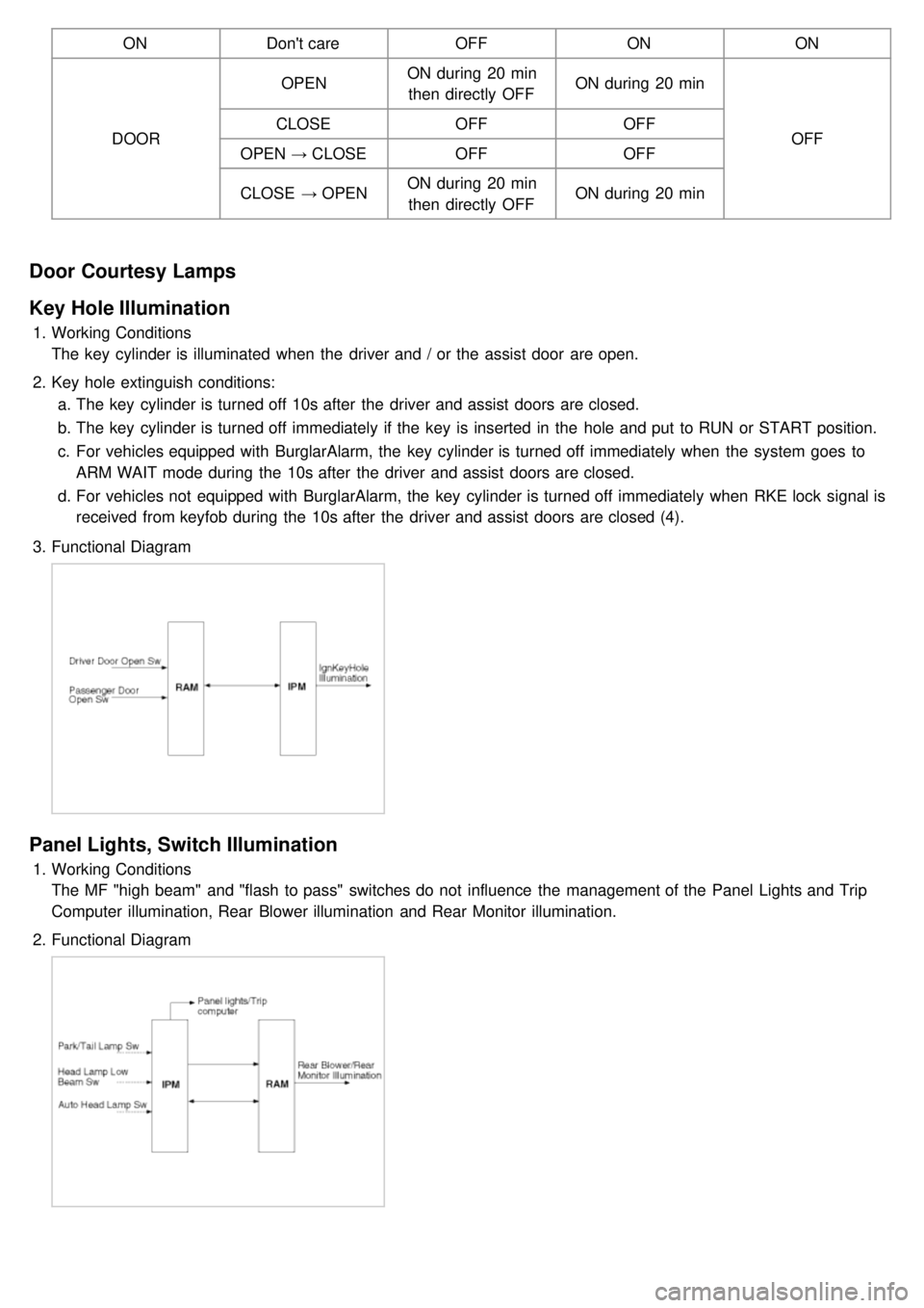
ONDon't care OFFONON
DOOR OPEN
ON during 20 min
then directly OFF ON during 20 min
OFF
CLOSE
OFFOFF
OPEN → CLOSE OFF OFF
CLOSE → OPEN ON during 20 min
then directly OFF ON during 20 min
Door Courtesy Lamps
Key Hole Illumination
1.
Working Conditions
The key cylinder is illuminated when the driver and / or the assist door are open.
2. Key hole extinguish conditions:
a. The key cylinder is turned off 10s after the driver and assist doors are closed.
b. The key cylinder is turned off immediately if the key is inserted in the hole and put to RUN or START position.
c. For vehicles equipped with BurglarAlarm, the key cylinder is turned off immediately when the system goes to
ARM WAIT mode during the 10s after the driver and assist doors are closed.
d. For vehicles not equipped with BurglarAlarm, the key cylinder is turned off immediately when RKE lock signal is
received from keyfob during the 10s after the driver and assist doors are closed (4).
3. Functional Diagram
Panel Lights, Switch Illumination
1.Working Conditions
The MF "high beam" and "flash to pass" switches do not influence the management of the Panel Lights and Trip
Computer illumination, Rear Blower illumination and Rear Monitor illumination.
2. Functional Diagram
Page 1248 of 1575

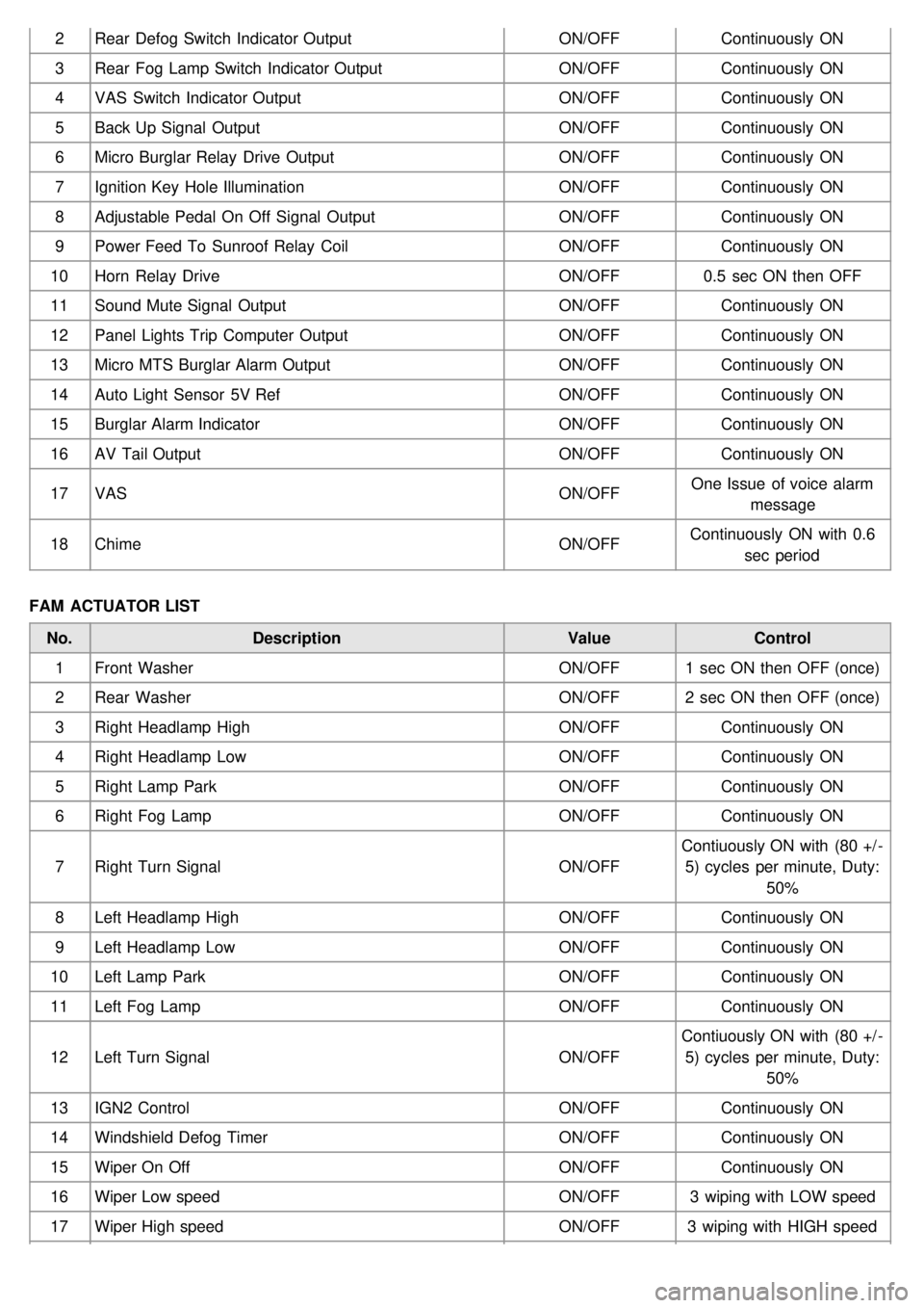
2Rear Defog Switch Indicator Output ON/OFFContinuously ON
3 Rear Fog Lamp Switch Indicator Output ON/OFFContinuously ON
4 VAS Switch Indicator Output ON/OFFContinuously ON
5 Back Up Signal Output ON/OFFContinuously ON
6 Micro Burglar Relay Drive Output ON/OFFContinuously ON
7 Ignition Key Hole Illumination ON/OFFContinuously ON
8 Adjustable Pedal On Off Signal Output ON/OFFContinuously ON
9 Power Feed To Sunroof Relay Coil ON/OFFContinuously ON
10 Horn Relay Drive ON/OFF0.5 sec ON then OFF
11 Sound Mute Signal Output ON/OFFContinuously ON
12 Panel Lights Trip Computer Output ON/OFFContinuously ON
13 Micro MTS Burglar Alarm Output ON/OFFContinuously ON
14 Auto Light Sensor 5V Ref ON/OFFContinuously ON
15 Burglar Alarm Indicator ON/OFFContinuously ON
16 AV Tail Output ON/OFFContinuously ON
17 VAS ON/OFFOne Issue of voice alarm
message
18 Chime ON/OFFContinuously ON with 0.6
sec period
FAM ACTUATOR LIST No. Description ValueControl
1 Front Washer ON/OFF1 sec ON then OFF (once)
2 Rear Washer ON/OFF2 sec ON then OFF (once)
3 Right Headlamp High ON/OFFContinuously ON
4 Right Headlamp Low ON/OFFContinuously ON
5 Right Lamp Park ON/OFFContinuously ON
6 Right Fog Lamp ON/OFFContinuously ON
7 Right Turn Signal ON/OFFContiuously ON with (80 +/ -
5) cycles per minute, Duty: 50%
8 Left Headlamp High ON/OFFContinuously ON
9 Left Headlamp Low ON/OFFContinuously ON
10 Left Lamp Park ON/OFFContinuously ON
11 Left Fog Lamp ON/OFFContinuously ON
12 Left Turn Signal ON/OFFContiuously ON with (80 +/ -
5) cycles per minute, Duty: 50%
13 IGN2 Control ON/OFFContinuously ON
14 Windshield Defog Timer ON/OFFContinuously ON
15 Wiper On Off ON/OFFContinuously ON
16 Wiper Low speed ON/OFF3 wiping with LOW speed
17 Wiper High speed ON/OFF3 wiping with HIGH speed
Page 1310 of 1575
4.Connect the oil pressure switch wire harness.
5. Turn the ignition switch ON. Check that the warning lamp lights up. If the warning lamp doesn't light, test the wire
harness.
BRAKE FLUID LEVEL WARNING SWITCH
1.Remove the connector (A) from the switch located at the brake fluid reservoir (B).
2. Verify that continuity exists between switch terminals 1 and 2 while pressing the switch (float) down with a rod.
BRAKE FLUID LEVEL WARNING LAMP
1.Ignition "ON"
2. Release the parking brake.
3. Remove the connector from the brake fluid level warning switch.
4. Ground the connector at the harness side.
5. Verify that the warning lamp lights.
PARKING BRAKE SWITCH
The parking brake switch is a push type. It is located at the side of the parking brake pedal.
1. Check that there is continuity between the terminal and switch body with the switch (A) ON.
Page 1447 of 1575
2007 > 2.7L V6 GASOLINE >
DESCRIPTION
The electrochromatic rear view mirror detects the ambient light using a built- in sensor and adjusts the reflectability of
the mirror to prevent excess light (such as the light emitted by a following vehicle's headlights) from reaching the
driver's eyes during night driving. To allow for maximum vision while backing up, the electrochromatic functionality of
the mirror is deactivated whenever the transaxle is in 'R' range.
1.The front sensor sees if the brightness of the surroundings is low enough for the mirror to operate its function.
2. The rearward looking sensor detects glaring of the reflecting light from a following vehicle.
3. The ECM is darkened to the level as determined by the rearward looking sensor. When the glaring is no longer
detected, the mirror stops functioning.
Page 1497 of 1575
Page 1498 of 1575
Daytime Running LightsControl Module