Page 4136 of 6020

UNIT REPAIR (AW30–40LE) 7A4–1
SECTION 7A4
TABLE OF CONTENTS
UNIT REPAIR (AW30–40LE)
Major Components (1) ................................... 7A4–2Major Components (1) and Associatedparts ........................................................... 7A4–2
Disassembly steps ...................................... 7A4–2
Components (1) ............................................. 7A4–4 Reassembly ................................................ 7A4–4
Major Components (2) ................................... 7A4–6 Major Componets (2) and Associated Parts ........................................................... 7A4–6
Disassembly ............................................... 7A4–7
Reassembly ................................................ 7A4–10
Major Components (3) ................................... 7A4–15 Major Components (3) and AssociatedParts ........................................................... 7A4–15
Disassembly ............................................... 7A4–16
Reassembly ................................................ 7A4–24
Diaassembly, Inspection and Reassembly of minor Components ................................. 7A4–36
Oil Pump ........................................................ 7A4–37 Disassembly View ...................................... 7A4–37
Disassembly ............................................... 7A4–37
Inspection and Repair ................................. 7A4–38
Reassembly ................................................ 7A4–40
OD Planetary Gear and OD Direct Clutch Assembly (C–0).......................................... 7A4–42
Disassembled View .................................... 7A4–42
Disassembly ............................................... 7A4–43
Inspection and Repair ................................. 7A4–46
Reassembly ................................................ 7A4–47
OD Support Assembly ................................... 7A4–52 Disassembled View .................................... 7A4–52
Disassembly ............................................... 7A4–52
Inspection and Repair ................................. 7A4–53
Reassembly ................................................ 7A4–54
Direct Clutch Assembly (C-2) ........................ 7A4–57 Disassembled View .................................... 7A4–57
Disassembly ............................................... 7A4–58
Inspection and Repair ................................. 7A4–59
Reassembly ................................................ 7A4–60
Forward Clutch Asseembly (C-1)................... 7A4–63 Disassembled View .................................... 7A4–63
Disassembly ............................................... 7A4–64
Inspection and Repair ................................. 7A4–65 Reassembly ................................................ 7A4–66
Front Planetary Gear ..................................... 7A4–70 Disassembled View .................................... 7A4–70
Disassembly ............................................... 7A4–70
Inspection and Repair ................................. 7A4–70
Reassembly ................................................ 7A4–71
Planetary Sun Gear and No.1 One-Way Clutch ......................................................... 7A4–72
Disassembled View .................................... 7A4–72
Disassembly ............................................... 7A4–73
Inspection and Repair ................................. 7A4–73
Reassembly ................................................ 7A4–74
Second Brake Assembly (B–2) ...................... 7A4–76 Disassembled View .................................... 7A4–76
Disassembly ............................................... 7A4–76
Inspection and Repair ................................. 7A4–77
Reassembly ................................................ 7A4–77
Rear Planetary Gear Assembly and Output Shaft ........................................................... 7A4–80
Disassembled View .................................... 7A4–80
Disassembly ............................................... 7A4–81
Reassembly ................................................ 7A4–83
First and Reverse Brake (B–3) ...................... 7A4–86 Disassembled View .................................... 7A4–86
Disassembly ............................................... 7A4–87
Reassembly ................................................ 7A4–88
Transmission Case ........................................ 7A4–91 Disassembled View .................................... 7A4–91
Disassembly ............................................... 7A4–91
Reassembly ................................................ 7A4–92
Torque Converter........................................... 7A4–94 Inspection and Repair ................................. 7A4–94
Adapter Housing (4 × 4)................................. 7A4–95
Disassembled View .................................... 7A4–95
Disassembly ............................................... 7A4–95
Reassembly ................................................ 7A4–95
Extension Housing (4 × 2) ............................. 7A4–96
Disassembled View .................................... 7A4–96
Disassembly ............................................... 7A4–96
Reassembly ................................................ 7A4–97
Main Data and Specifications ........................ 7A4–98
Special Tools ................................................. 7A4–102
BACK TO CHAPTER INDEX
TO MODEL INDEX
ISUZU KB P190 2007
Page 4137 of 6020
7A4–2 UNIT REPAIR (AW30–40LE)
Major Components (1)
Major Components (1) and Associated parts
RTW77AMF003801
EndOFCallout
Disassembly steps
1. Remove the torque converter.
2. Remove the select lever.
Legend (1) Torque converter
(2) Neutral start switch
(3) Elbow
(4) Oil temperature sensor
(5) Breather hose (6) Output revolution sensor
(7) Adapter housing
(8) Transmission assembly
(9) Select lever
(10) Input revolution sensor
BACK TO CHAPTER INDEX
TO MODEL INDEX
ISUZU KB P190 2007
Page 4139 of 6020

7A4–4 UNIT REPAIR (AW30–40LE)
Components (1)
Reassembly
1. Install a new gasket and the extension housing(4×2) to the transmission case.
Torque: 36 N·m (3.7 kgf·m/27 Ib ·ft)
2. Install the speedometer driven gear, plate, and speedometer sensor (4 ×2).
Torque:
Plate bolt – 15 N·m (1.5 kgf·m/11 Ib ·ft)
Speedometer sensor – 25 N·m (2.5 kgf·m/18 Ib ·ft)
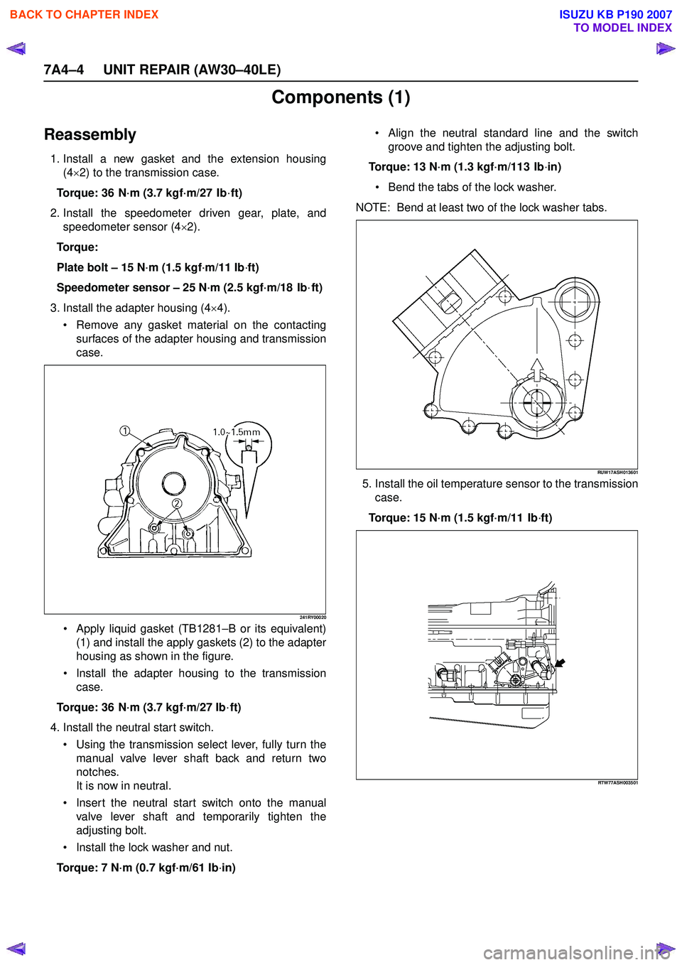
3. Install the adapter housing (4 ×4).
Remove any gasket material on the contacting
surfaces of the adapter housing and transmission
case.
241RY00020
Apply liquid gasket (TB1281 –B or its equivalent)
(1) and install the apply gaskets (2) to the adapter
housing as shown in the figure.
Install the adapter housing to the transmission
case.
Torque: 36 N·m (3.7 kgf·m/27 Ib ·ft)
4. Install the neutral start switch. Using the transmission select lever, fully turn the
manual valve lever shaft back and return two
notches.
It is now in neutral.
Insert the neutral start switch onto the manual
valve lever shaft and temporarily tighten the
adjusting bolt.
Install the lock washer and nut.
Torque: 7 N·m (0.7 kgf·m/61 Ib ·in)
Align the neutral standard line and the switch
groove and tighten the adjusting bolt.
Torque: 13 N·m (1.3 kgf·m/113 Ib ·in)
Bend the tabs of the lock washer.
NOTE: Bend at least two of the lock washer tabs.
RUW17ASH013601
5. Install the oil temperature sensor to the transmission case.
Torque: 15 N·m (1.5 kgf·m/11 Ib ·ft)
RTW77ASH003501
BACK TO CHAPTER INDEX
TO MODEL INDEX
ISUZU KB P190 2007
Page 4140 of 6020
UNIT REPAIR (AW30–40LE) 7A4–5
6. Install the elbow. Coat new O-rings with ATF, install them to the two
elbows.
Install the two elbows as shown in the figure.
Torque: 29 N ·m (3.0 kgf ·m/22 Ib ·ft)
RTW77ASH003601
7. Install the select lever.
8. Install the output revolution sensor (4 ×2).
9. Install the output revolution sensor (4 ×4).
10. Install the input revolution sensor.
11. Install the breather hose.
12. Install the torque converter. Using calipers and a straightedge, measure the
distance from the installed surface of the
transmission housing to top of the torque converter
nut.
Correct distance: 13.5 mm (0.53 in)
240RY00005
BACK TO CHAPTER INDEX
TO MODEL INDEX
ISUZU KB P190 2007
Page 4145 of 6020
7A4–10 UNIT REPAIR (AW30–40LE)
16. Remove the spacer, rotor, key and snap ring (4×2).
Remove the spacer, rotor and key.
Remove the snap ring from the output shaft.
247L100001
Reassembly
1. Install the converter housing.
Torque:
M10 – 34 N ·m (3.5 kgf ·m/25 lb ·ft)
M12 – 57 N ·m (5.8 kgf ·m/42 lb ·ft)
240R200022
2. Install the snap ring, key and rotor (4 ×2).
Install the snap ring to the output shaft.
Install the key and rotor. 3. Install the spacer, ball, speedometer sensor drive
gear and snap ring (4 ×2).
Install the spacer, ball and speedometer sensor
drive gear.
Install the snap ring to the output shaft.
247L100001
4. Install the key, rotor and snap ring (4 ×4).
Install the key and rotor.
Install the snap ring to the output shaft.
247R200002
BACK TO CHAPTER INDEX
TO MODEL INDEX
ISUZU KB P190 2007
Page 4147 of 6020
7A4–12 UNIT REPAIR (AW30–40LE)
240RY00029
240RY00010
8. Install new check valve and spring.
240RY00016
9. Install the valve body. Align the groove of the manual valve to the pin of
the lever.
240RY00017
Install the twenty bolts.
NOTE: Each bolt length (mm) is indicated in the figure. Torque: 10 N ·m (1.0 kgf ·m/87 lb ·in)
244R200078
BACK TO CHAPTER INDEX
TO MODEL INDEX
ISUZU KB P190 2007
Page 4148 of 6020
UNIT REPAIR (AW30–40LE) 7A4–13
10. Install the solenoid wiring.Coat a new O-ring with ATF, and install it to the
solenoid wiring.
Insert the solenoid wiring to the case and install the
stopper plate.
Connect the connectors to the solenoid S1 (1), S2
(2), lock-up solenoid (3), and pressure control
solenoid (4).
249RY00011
249RY00012
11. Install a new oil strainer assembly with gaskets.
244RY00002
Install the oil strainer with the gaskets to the valve
body. Tighten the four bolts.
Torque: 10 N ·m (1.0 kgf ·m/87 lb ·in)
244RY00003
BACK TO CHAPTER INDEX
TO MODEL INDEX
ISUZU KB P190 2007
Page 4149 of 6020
7A4–14 UNIT REPAIR (AW30–40LE)
12. Install the oil pan.Install two magnets in oil pan.
Remove any gasket material and be careful not to
drop oil on the contacting surfaces of the
transmission case and oil pan.
Apply liquid gasket (TB1281 or its equivalent) to the
oil pan as shown in the figure.
NOTE: Install the oil pan as soon as the seal gasket is
applied.
240RY00019
Install and tighten the nineteen bolts.
Torque: 7.4 N ·m (0.75 kgf ·m/65 lb ·in)
240RY00020
BACK TO CHAPTER INDEX
TO MODEL INDEX
ISUZU KB P190 2007