Page 4208 of 6020
UNIT REPAIR (AW30–40LE) 7A4–73
Disassembly
1. Check operation of No.1 one-way clutchHold the planetary sun gear and turn the second
brake hub.
The second brake hub should turn freely clockwise
and should lock counterclockwise.
RUW37ASH004601
E ndOFCallout
2. Remove the one-way clutch and second brake hub.
3. Remove the trust washer (plastic).
4. Remove two oil seal rings (metal).
248RY00052
5. Remove the snap ring with snap ring pliers.
248RY00053
6. Remove the sun gear input drum.
7. Remove the snap ring from planetary sun gear.
Inspection and Repair
1. Check planetary sun gear bushing Using a dial indicator, measure the inside diameter
of the planetary sun gear bushing.
Maximum inside diameter: 27.08 mm (1.066 in) If the inside diameter is greater than the maximum,
replace the planetary sun gear.
248RY00054
Legend
(1) Free
(2) Lock
BACK TO CHAPTER INDEX
TO MODEL INDEX
ISUZU KB P190 2007
Page 4209 of 6020
7A4–74 UNIT REPAIR (AW30–40LE)
Reassembly
1. Install snap ring to planetary sun gear.
248RY00055
2. Place a wooden block, etc. as a work stand andplace the planetary sun gear onto it.
Install the sun gear input drum onto the planetary
sun gear.
248RY00056
3. Install snap ring with snap ring pliers.
248RY00053
4. Coat the two oil seal rings (metal) with ATF. Install the two oil seal rings onto the planetary sun
gear.
NOTE: Do not spread the ring ends too much.
248RY00052
BACK TO CHAPTER INDEX
TO MODEL INDEX
ISUZU KB P190 2007
Page 4210 of 6020
UNIT REPAIR (AW30–40LE) 7A4–75
5. Install thrust washer (plastic).
NOTE: Make sure that the lugs fit into the holes on the
sun gear input drum.
248RY00057
6. Install assembled No.1 one-way clutch and second brake hub onto planetary sun gear as shown.
248RY00058
7. Check operation of No.1 one-way clutchHold the planetary sun gear and turn the second
brake hub.
The second brake hub should turn freely clockwise
and should lock counterclockwise.
RUW37ASH004601
En dOFCallout
Legend
(1) Free
(2) Lock
BACK TO CHAPTER INDEX
TO MODEL INDEX
ISUZU KB P190 2007
Page 4216 of 6020
UNIT REPAIR (AW30–40LE) 7A4–81
Disassembly
1. Remove second brake assembly from output shaft.
246RY00014
2. Remove oil seal ring from output shaft.
247RY00028
3. Remove the seven discs, seven plates and flange(B–3). 4. Remove rear planetary gear from rear planetary ring
gear.
247RY00029
5. Check operation of No.2 one-way clutch.Hold the planetary gear and turn the one-way clutch
inner race.
The one-way clutch inner race should turn freely
counterclockwise and should lock clockwise.
RUW37ASH004701
En dOFCallout
Legend
(1) Lock
(2) Free
BACK TO CHAPTER INDEX
TO MODEL INDEX
ISUZU KB P190 2007
Page 4219 of 6020
7A4–84 UNIT REPAIR (AW30–40LE)
7. While turning counterclockwise, install one-wayclutch inner race to rear planetary gear.
247RY00040
8. Check operation of one-way clutch.Hold the planetary gear and turn the one-way clutch
inner race.
The one-way clutch inner race should turn freely
counterclockwise and should lock clockwise.
RUW37ASH004701
E ndOFCallout
9. Install rear planetary gear onto rear planetary ring gear.
247RY00029
10. Install the disc, plate and flange (B –3).
Install a brake flange onto the rear planetary gear
assembly.
Install a clutch disc onto the rear planetary gear
assembly.
NOTE: The claw interval of the plate should be as
shown in the figure when viewing the clutch plate from
the arrow direction.
246RY00013
Legend
(1) Lock
(2) Free
BACK TO CHAPTER INDEX
TO MODEL INDEX
ISUZU KB P190 2007
Page 4229 of 6020
7A4–94 UNIT REPAIR (AW30–40LE)
Torque Converter
Inspection and Repair
Insert special tool in end of torque converter.
Insert a turning tool into the inner race of the one-way
clutch.
One-way clutch testing tool : 5-8840-2168-0
Insert the stopper so that it fits in the notch of the
converter hub and outer race of the one-way clutch.
241RY00018
1. One-way clutch test. The clutch should lock when turned
counterclockwise, and rotate freely and smoothly
clockwise. Less than 2.5 N ·m (0.25kgf ·m/22 Ib ·in) of
torque should be required to rotate the clutch
clockwise. If necessary, clean the converter and
retest the clutch. Replace the conver ter if the clutch
still fails the test.
BACK TO CHAPTER INDEX
TO MODEL INDEX
ISUZU KB P190 2007
Page 4233 of 6020

7A4–98 UNIT REPAIR (AW30–40LE)
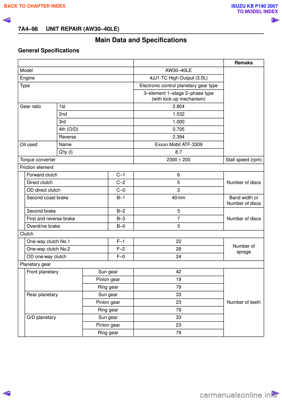
Main Data and Specifications
General Specifications
Remaks
Model AW30–40LE
Engine 4JJ1-TC High Output (3.0L)
Type Electronic control planetary gear type
3–element 1 –stage 2 –phase type
(with lock-up mechanism)
Gear ratio 1st 2.804
2nd 1.532
3rd 1.000
4th (O/D) 0.705
Reverse 2.394
Oil used Name Exxon Mobil ATF-3309
Q'ty (l) 8.7
Torque conver ter 2300 ± 200 Stall speed (rpm)
Friction element Forward clutch C–16
Number of discs
Direct clutch C–25
OD direct clutch C–03
Second coast brake B–1 40 mm Band width or
Number of discs
Second brake B–25
Number of discs
First and reverse brake B–37
Overdrive brake B–05
Clutch One-way clutch No.1 F–12 2
Number of
sprage
One-way clutch No.2
F–22 8
OD one-way clutch F–02 4
Planetary gear Front planetary Sun gear 42
Number of teeth
Pinion gear
19
Ring gear 79
Rear planetary Sun gear 33
Pinion gear 23
Ring gear 79
O/D planetary Sun gear 33
Pinion gear 23
Ring gear 79
BACK TO CHAPTER INDEX
TO MODEL INDEX
ISUZU KB P190 2007
Page 4240 of 6020

CONSTRUCTION AND FUNCTION 7A1-1
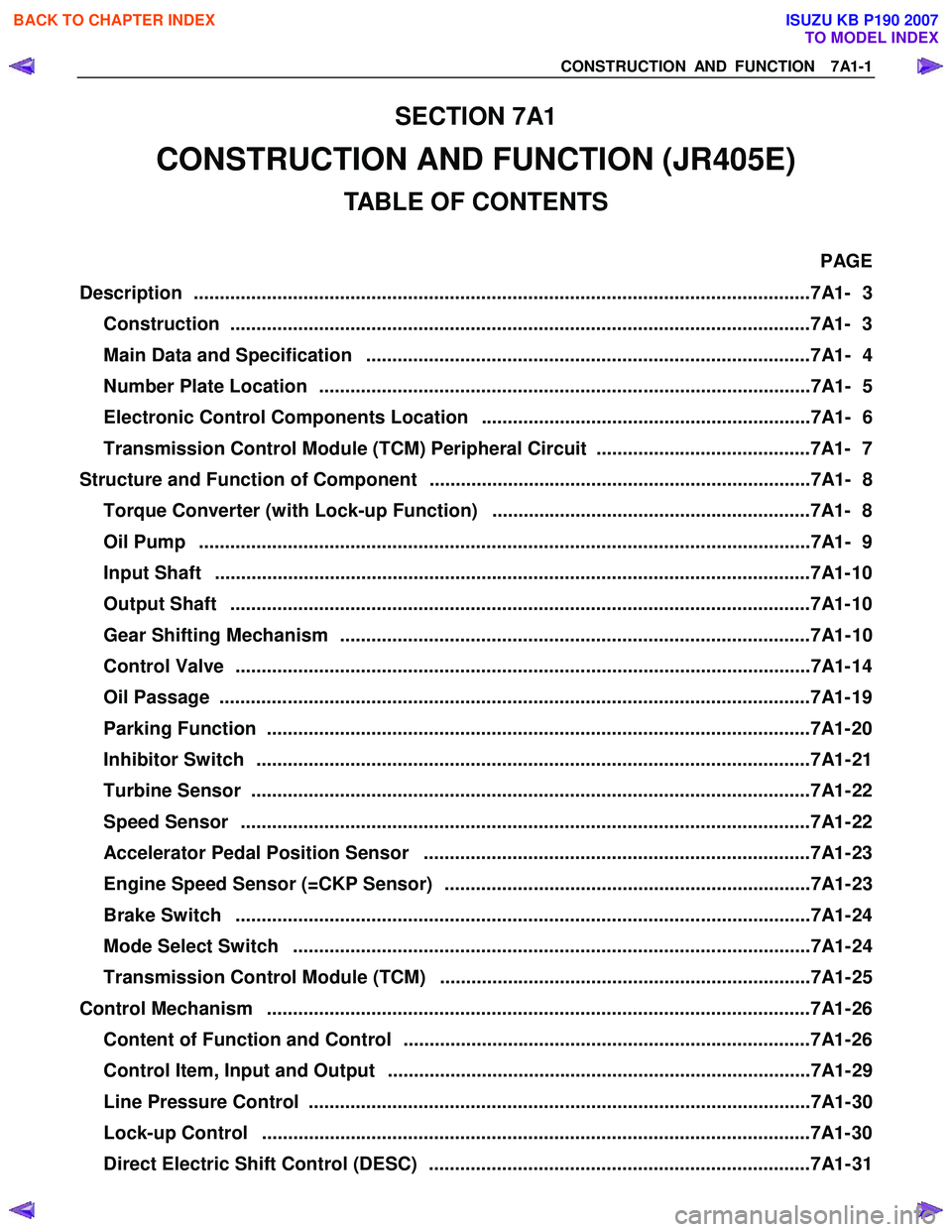
SECTION 7A1
CONSTRUCTION AND FUNCTION (JR405E)
TABLE OF CONTENTS
PAGE
Description ................................................................................................................... ...7A1- 3
Construction ...............................................................................................................7A1 - 3
Main Data and Specification .....................................................................................7A1- 4
Number Plate Location ..............................................................................................7A1- 5
Electronic Control Components Location ...............................................................7A1- 6
Transmission Control Module (TCM) Peripheral Circuit .........................................7A1- 7
Structure and Function of Component .........................................................................7A1- 8
Torque Converter (with Lock-up Function) .............................................................7A1- 8
Oil Pump .....................................................................................................................7 A1- 9
Input Shaft ..................................................................................................................7 A1- 10
Output Shaft ...............................................................................................................7A1 - 10
Gear Shifting Mechanism ..........................................................................................7A1- 10
Control Valve ..............................................................................................................7A1 - 14
Oil Passage .................................................................................................................7A 1- 19
Parking Function ........................................................................................................7A1- 2 0
Inhibitor Switch ..........................................................................................................7A1- 21
Turbine Sensor ...........................................................................................................7A1- 22
Speed Sensor .............................................................................................................7A1- 22
Accelerator Pedal Position Sensor ..........................................................................7A1- 23
Engine Speed Sensor (=CKP Sensor) ......................................................................7A1- 23
Brake Switch ..............................................................................................................7A1- 24
Mode Select Switch ...................................................................................................7A1- 24
Transmission Control Module (TCM) .......................................................................7A1- 25
Control Mechanism ........................................................................................................7A1- 26
Content of Function and Control ..............................................................................7A1- 26
Control Item, Input and Output .................................................................................7A1- 29
Line Pressure Control ................................................................................................7A1- 30
Lock-up Control .........................................................................................................7A1- 3 0
Direct Electric Shift Control (DESC) .........................................................................7A1- 31
BACK TO CHAPTER INDEX
TO MODEL INDEX
ISUZU KB P190 2007