2007 ISUZU KB P190 lock
[x] Cancel search: lockPage 4280 of 6020
CONSTRUCTION AND FUNCTION 7A1-41
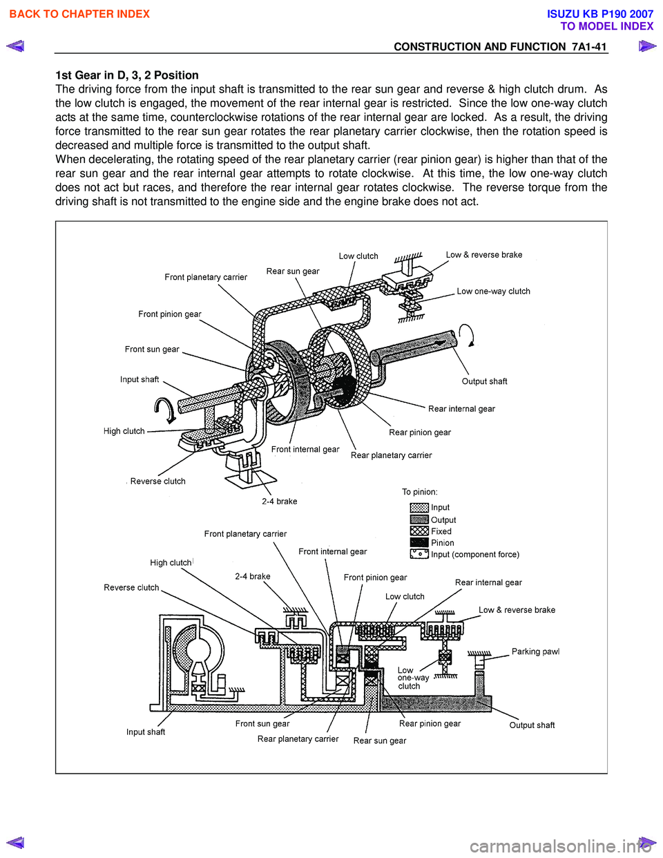
1st Gear in D, 3, 2 Position
The driving force from the input shaft is transmitted to the rear sun gear and reverse & high clutch drum. As
the low clutch is engaged, the movement of the rear internal gear is restricted. Since the low one-way clutch
acts at the same time, counterclockwise rotations of the rear internal gear are locked. As a result, the driving
force transmitted to the rear sun gear rotates the rear planetary carrier clockwise, then the rotation speed is
decreased and multiple force is transmitted to the output shaft.
When decelerating, the rotating speed of the rear planetary carrier (rear pinion gear) is higher than that of the
rear sun gear and the rear internal gear attempts to rotate clockwise. At this time, the low one-way clutch
does not act but races, and therefore the rear internal gear rotates clockwise. The reverse torque from the
driving shaft is not transmitted to the engine side and the engine brake does not act.
BACK TO CHAPTER INDEX
TO MODEL INDEX
ISUZU KB P190 2007
Page 4282 of 6020
CONSTRUCTION AND FUNCTION 7A1-43
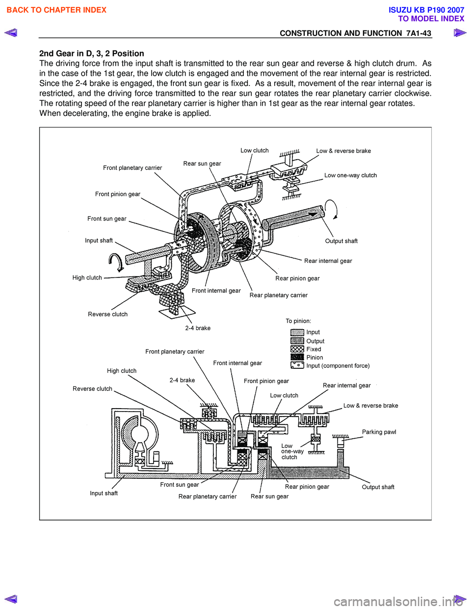
2nd Gear in D, 3, 2 Position
The driving force from the input shaft is transmitted to the rear sun gear and reverse & high clutch drum. As
in the case of the 1st gear, the low clutch is engaged and the movement of the rear internal gear is restricted.
Since the 2-4 brake is engaged, the front sun gear is fixed. As a result, movement of the rear internal gear is
restricted, and the driving force transmitted to the rear sun gear rotates the rear planetary carrier clockwise.
The rotating speed of the rear planetary carrier is higher than in 1st gear as the rear internal gear rotates.
When decelerating, the engine brake is applied.
BACK TO CHAPTER INDEX
TO MODEL INDEX
ISUZU KB P190 2007
Page 4284 of 6020
CONSTRUCTION AND FUNCTION 7A1-45
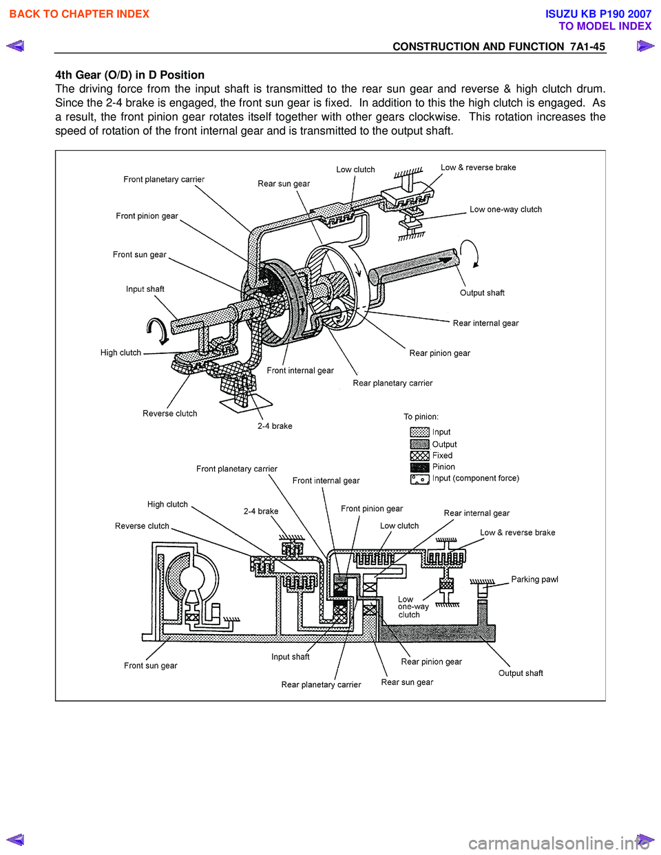
4th Gear (O/D) in D Position
The driving force from the input shaft is transmitted to the rear sun gear and reverse & high clutch drum.
Since the 2-4 brake is engaged, the front sun gear is fixed. In addition to this the high clutch is engaged. As
a result, the front pinion gear rotates itself together with other gears clockwise. This rotation increases the
speed of rotation of the front internal gear and is transmitted to the output shaft.
BACK TO CHAPTER INDEX
TO MODEL INDEX
ISUZU KB P190 2007
Page 4285 of 6020

TRANSMISSION CONTROL SYSTEM (JR405E) 7A2-1
TRANSMISSION
TRANSMISSION CONTROL SYSTEM (JR405E)
This manual conforms when Scan Tool of ISO CAN Base Software is used.
TABLE OF CONTENTS
Specifications ...................................................... 7A2-2Transmission General Specifications ............... 7A2-2
Transmission Fluid Temperature vs. Resistance..... 7A2-3
Clutch, Brake, Solenoid and Pressure Switch Logic........ 7A2-4
Diagnostic Trouble Code (DTC) List ................ 7A2-5
Schematic and Routing Diagrams....................... 7A2-6 Transmission Controls Schematics .................. 7A2-6
Component Locator........................................... 7A2-13 Transmission Controls Component Views ..... 7A2-13
Transmission Control Module (TCM) Connector End Views ................................... 7A2-17
Transmission Control Connector End Views.. 7A2-18
Diagnostic Information and Procedures ............ 7A2-21
Diagnostic Starting Point - Transmission Controls......... 7A2-21
Diagnostic System Check - Transmission Controls....... 7A2-22
Scan Tool Data List ........................................ 7A2-24
Scan Tool Data Definitions............................. 7A2-25
Scan Tool Output Controls ............................. 7A2-27
Scan Tool Does Not Power Up ...................... 7A2-28
Scan Tool Does Not Communicate with Keyword Device .................................... 7A2-29
Lost Communication with The Transmission Control Module (TCM)
.... 7A2-31
DTC P0560 (Flash Code 16).......................... 7A2-33
DTC P0602 .................................................... 7A2-35
DTC P0705 (Flash Code 17).......................... 7A2-36
DTC P0710 (Flash Code 15).......................... 7A2-40
DTC P0717 (Flash Code 14).......................... 7A2-44
DTC P0722 (Flash Code 11).......................... 7A2-47
DTC P0727 (Flash Code 13).......................... 7A2-50
DTC P0731, P0732, P0733 or P0734 (Flash Code 41, 42, 43 or 44)....................... 7A2-52
DTC P0748 (Flash Code 35).......................... 7A2-55
DTC P0753 (Flash Code 31).......................... 7A2-58
DTC P0758 (Flash Code 32).......................... 7A2-61
DTC P0763 (Flash Code 33).......................... 7A2-64
DTC P0768 (Flash Code 34).......................... 7A2-67
DTC P1120 (Flash Code 22).......................... 7A2-70
DTC P1750 (Flash Code 51).......................... 7A2-71
DTC P1755 (Flash Code 52).......................... 7A2-73
DTC P1853 (Flash Code 26).......................... 7A2-75
DTC P1858 (Flash Code 27).......................... 7A2-78
DTC P1860 (Flash Code 36).......................... 7A2-81
DTC P1863 (Flash Code 28).......................... 7A2-84
DTC P1875 (Flash Code 25).......................... 7A2-87
Check Trans Lamp Inoperative, Always On or Always Blinking ...................... 7A2-89
Symptoms - Transmission Controls .................. 7A2-92 Symptoms - Transmission Controls ............... 7A2-92
Intermittent Conditions ................................... 7A2-93 Vehicle Does Not Run .................................... 7A2-95
Trouble at Starting.......................................... 7A2-95
Faulty Gearshift .............................................. 7A2-95
Faulty Shift Pattern......................................... 7A2-95
No or Error Gearshift ...................................... 7A2-95
Faulty Operation During Running................... 7A2-95
Faulty Operation in Stopping.......................... 7A2-95
Faulty Lock Up ............................................... 7A2-95
No Lock Up .................................................... 7A2-95
Transmission Fluid Leak ................................ 7A2-95
Others ............................................................ 7A2-95
Test Instructions .............................................. 7A2-121 Line Pressure Test ....................................... 7A2-121
Stall Test ...................................................... 7A2-123
Time Lag Test .............................................. 7A2-124
Road Test..................................................... 7A2-125
TCM Signal Test .......................................... 7A2-134
Repair Instructions .......................................... 7A2-139
Transmission Controls Module (TCM) Replacement.... 7A2-139
Service Programming System (SPS) Description........ 7A2-139
Service Programming System (SPS) (Remote Procedure)......................... 7A2-140
Service Programming System (SPS) (Pass-Thru Procedure)..................... 7A2-141
Description and Operation .............................. 7A2-143 Transmission Identification Information........ 7A2-143
Transmission General Description ............... 7A2-143
Transmission Component Description ......... 7A2-144
Transmission Control System Description ... 7A2-152
Transmission Power Flow Description ......... 7A2-161
Special Tools and Equipment ......................... 7A2-170 Special Tools and Equipment ...................... 7A2-170
BACK TO CHAPTER INDEX
TO MODEL INDEX
ISUZU KB P190 2007
Page 4289 of 6020
TRANSMISSION CONTROL SYSTEM (JR405E) 7A2-5
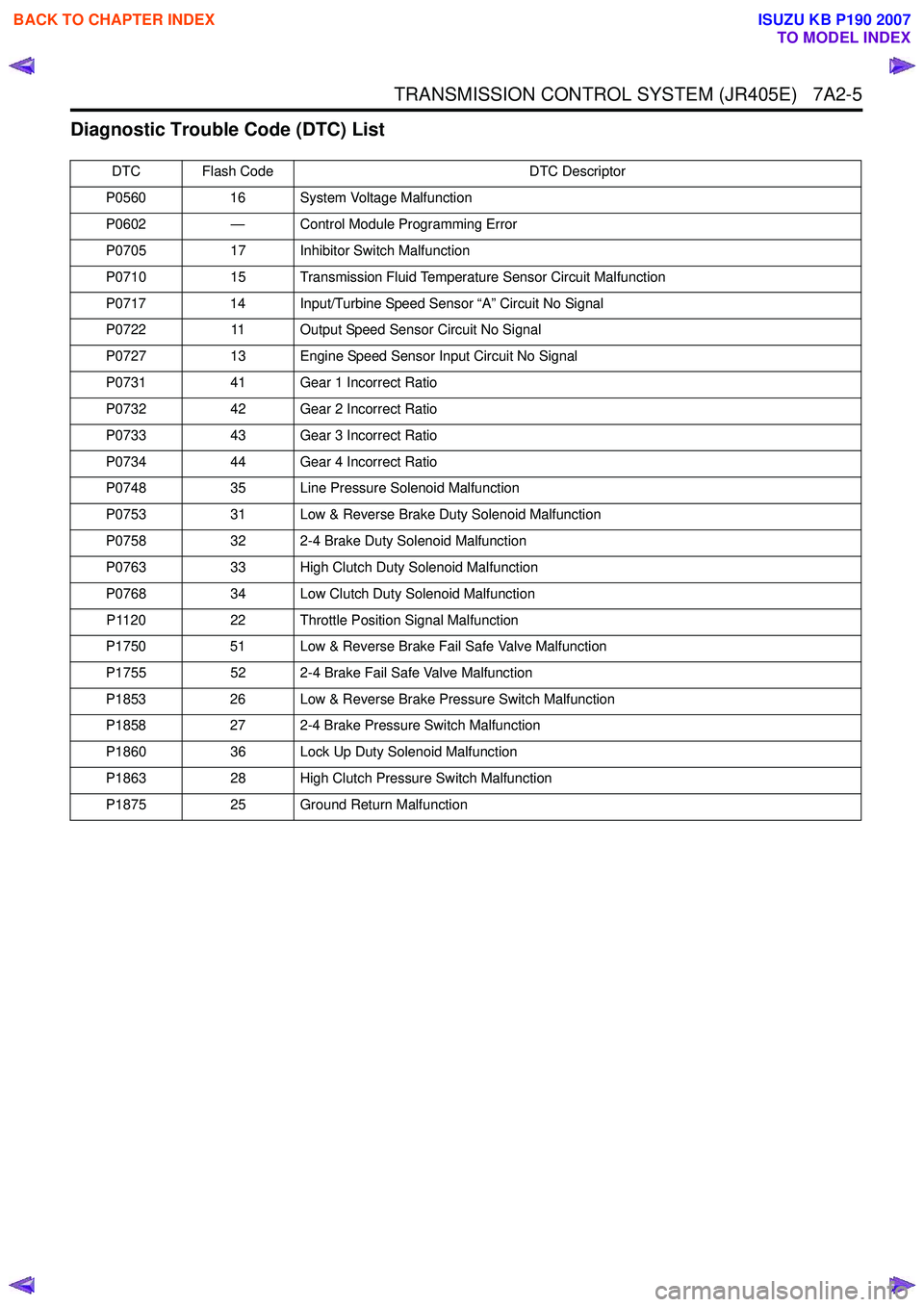
Diagnostic Trouble Code (DTC) List
DTC Flash CodeDTC Descriptor
P0560 16 System Voltage Malfunction
P0602 — Control Module Programming Error
P0705 17 Inhibitor Switch Malfunction
P0710 15 Transmission Fluid Temperature Sensor Circuit Malfunction
P0717 14 Input/Turbine Speed Sensor “A” Circuit No Signal
P0722 11 Output Speed Sensor Circuit No Signal
P0727 13 Engine Speed Sensor Input Circuit No Signal
P0731 41 Gear 1 Incorrect Ratio
P0732 42 Gear 2 Incorrect Ratio
P0733 43 Gear 3 Incorrect Ratio
P0734 44 Gear 4 Incorrect Ratio
P0748 35 Line Pressure Solenoid Malfunction
P0753 31 Low & Reverse Brake Duty Solenoid Malfunction
P0758 32 2-4 Brake Duty Solenoid Malfunction
P0763 33 High Clutch Duty Solenoid Malfunction
P0768 34 Low Clutch Duty Solenoid Malfunction
P1120 22 Throttle Position Signal Malfunction
P1750 51 Low & Reverse Brake Fail Safe Valve Malfunction
P1755 52 2-4 Brake Fail Safe Valve Malfunction
P1853 26 Low & Reverse Brake Pressure Switch Malfunction
P1858 27 2-4 Brake Pressure Switch Malfunction
P1860 36 Lock Up Duty Solenoid Malfunction
P1863 28 High Clutch Pressure Switch Malfunction
P1875 25 Ground Return Malfunction
BACK TO CHAPTER INDEX
TO MODEL INDEX
ISUZU KB P190 2007
Page 4300 of 6020
7A2-16 TRANSMISSION CONTROL SYSTEM (JR405E)
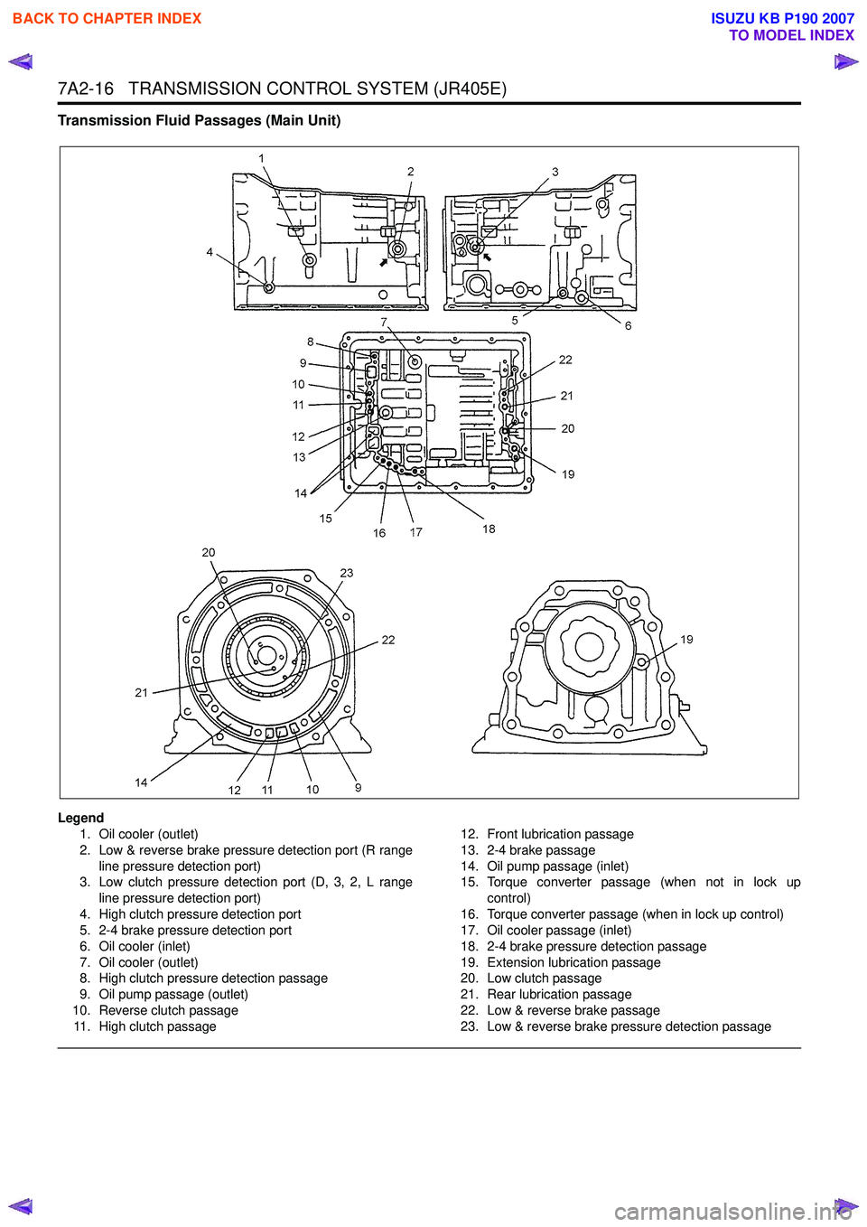
Transmission Fluid Passages (Main Unit)
Legend1. Oil cooler (outlet)
2. Low & reverse brake pressure detection port (R range line pressure detection port)
3. Low clutch pressure detection port (D, 3, 2, L range
line pressure detection port)
4. High clutch pressure detection port
5. 2-4 brake pressure detection port
6. Oil cooler (inlet)
7. Oil cooler (outlet)
8. High clutch pressure detection passage
9. Oil pump passage (outlet)
10. Reverse clutch passage 11. High clutch passage 12. Front lubrication passage
13. 2-4 brake passage
14. Oil pump passage (inlet)
15. Torque converter passage (when not in lock up
control)
16. Torque converter passage (when in lock up control)
17. Oil cooler passage (inlet)
18. 2-4 brake pressure detection passage
19. Extension lubrication passage
20. Low clutch passage
21. Rear lubrication passage
22. Low & reverse brake passage
23. Low & reverse brake pressure detection passage
BACK TO CHAPTER INDEX
TO MODEL INDEX
ISUZU KB P190 2007
Page 4312 of 6020
7A2-28 TRANSMISSION CONTROL SYSTEM (JR405E)
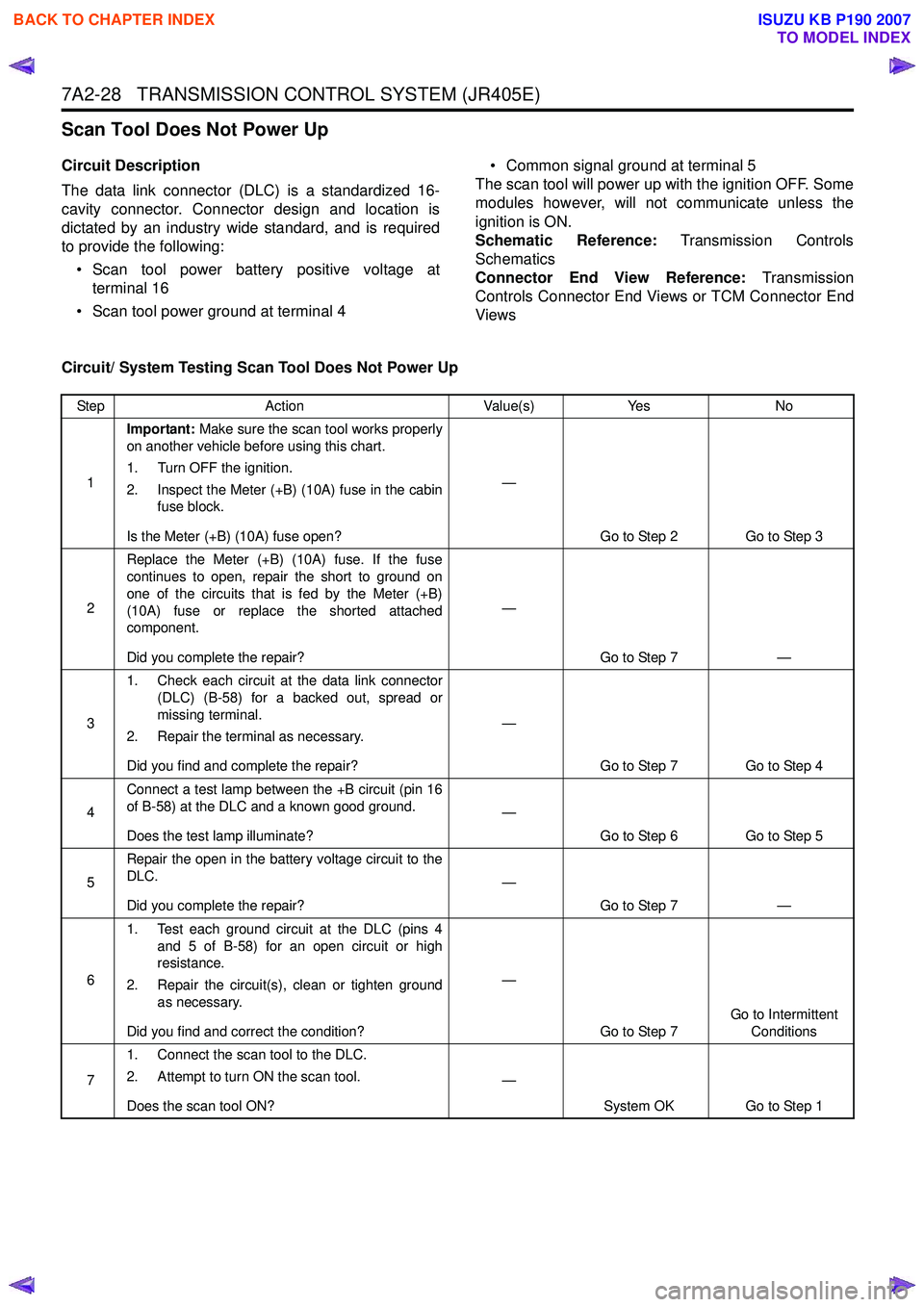
Scan Tool Does Not Power Up
Circuit Description
The data link connector (DLC) is a standardized 16-
cavity connector. Connector design and location is
dictated by an industry wide standard, and is required
to provide the following:
• Scan tool power battery positive voltage at terminal 16
• Scan tool power ground at terminal 4 • Common signal ground at terminal 5
The scan tool will power up with the ignition OFF. Some
modules however, will not communicate unless the
ignition is ON.
Schematic Reference: Transmission Controls
Schematics
Connector End View Reference: Transmission
Controls Connector End Views or TCM Connector End
Views
Circuit/ System Testing Scan Tool Does Not Power Up
Step Action Value(s)Yes No
1 Important:
Make sure the scan tool works properly
on another vehicle before using this chart.
1. Turn OFF the ignition.
2. Inspect the Meter (+B) (10A) fuse in the cabin fuse block.
Is the Meter (+B) (10A) fuse open? —
Go to Step 2 Go to Step 3
2 Replace the Meter (+B) (10A) fuse. If the fuse
continues to open, repair the short to ground on
one of the circuits that is fed by the Meter (+B)
(10A) fuse or replace the shorted attached
component.
Did you complete the repair? —
Go to Step 7 —
3 1. Check each circuit at the data link connector
(DLC) (B-58) for a backed out, spread or
missing terminal.
2. Repair the terminal as necessary.
Did you find and complete the repair? —
Go to Step 7 Go to Step 4
4 Connect a test lamp between the +B circuit (pin 16
of B-58) at the DLC and a known good ground.
Does the test lamp illuminate? —
Go to Step 6 Go to Step 5
5 Repair the open in the battery voltage circuit to the
DLC.
Did you complete the repair? —
Go to Step 7 —
6 1. Test each ground circuit at the DLC (pins 4
and 5 of B-58) for an open circuit or high
resistance.
2. Repair the circuit(s), clean or tighten ground as necessary.
Did you find and correct the condition? —
Go to Step 7 Go to Intermittent
Conditions
7 1. Connect the scan tool to the DLC.
2. Attempt to turn ON the scan tool.
Does the scan tool ON? —
System OK Go to Step 1
BACK TO CHAPTER INDEX
TO MODEL INDEX
ISUZU KB P190 2007
Page 4313 of 6020
![ISUZU KB P190 2007 Workshop Repair Manual TRANSMISSION CONTROL SYSTEM (JR405E) 7A2-29
Scan Tool Does Not Communicate with Keyword Device
Circuit Description
The TCM, electronic hydraulic control unit (EHCU)
[ABS module] and supplemental r ISUZU KB P190 2007 Workshop Repair Manual TRANSMISSION CONTROL SYSTEM (JR405E) 7A2-29
Scan Tool Does Not Communicate with Keyword Device
Circuit Description
The TCM, electronic hydraulic control unit (EHCU)
[ABS module] and supplemental r](/manual-img/61/57177/w960_57177-4312.png)
TRANSMISSION CONTROL SYSTEM (JR405E) 7A2-29
Scan Tool Does Not Communicate with Keyword Device
Circuit Description
The TCM, electronic hydraulic control unit (EHCU)
[ABS module] and supplemental restraint system
(SRS) control module all communicate with the scan
tool over the Keyword serial data link.
Diagnostic Aids
The following conditions will cause a loss of Keyword
serial data communication between the scan tool and
the TCM.
• A Keyword serial data circuit open • A Keyword serial data circuit shorted to ground
• A Keyword serial data circuit shorted to voltage
• An internal condition within a module or connector on the Keyword serial data circuit, that causes a
short to voltage or ground to the Keyword serial
data circuit
Schematic Reference: Transmission Controls
Schematics
Connector End View Reference: Transmission
Controls Connector End Views or TCM Connector End
Views
Circuit/ System Testing Scan Tool Does Not Communicate with Keyward Device
Step Action Value(s)Yes No
1 Did you perform the Diagnostic System Check -
Engine Controls? —
Go to Step 2 Go to Diagnostic
System Check - Transmission Controls
2 1. Install a scan tool.
2. Turn ON the ignition, with the engine OFF.
3. Attempt to establish communication with the listed control modules.
•TCM
• Electronic hydraulic control unit (EHCU) [ABS module] (If so equipped)
• Supplemental restraint system (SRS) control module (If so equipped)
Does the scan tool communicate with any of the
listed control modules? —
Go to Step 3 Go to Step 7
3 Does the scan tool communicate with the TCM?
—Go to Step 4 Go to Lost
Communication with
The Transmission Control Module (TCM)
4 Notice:
If no ABS is installed, skip to Step 5.
Does the scan tool communicate with the EHCU? —
Go to Step 5 Go to Diagnostic
System Check - Anti-lock Brake Controls
5 Notice:
If no SRS is installed, skip to Step 6.
Does the scan tool communicate with the SRS
control module? —
Go to Step 6 Go to Diagnostic
System Check -SRS Controls
6 Test the Keyword serial data circuit for an
intermittently short to ground or intermittently short
to voltage. Then, test the Keyword serial data
circuit for an intermittently open (based on which
control module did not communicate) at the
connection in the circuit.
Did you find and correct the condition? —
Go to Step 15 System OK
7 1. Inspect for an intermittent, for a poor
connection and for corrosion at the data link
connector (DLC) (pin 7 of B-58).
2. Repair the connection(s) as necessary.
Did you find and correct the condition? —
Go to Step 15 Go to Step 8
BACK TO CHAPTER INDEX
TO MODEL INDEX
ISUZU KB P190 2007