2007 ISUZU KB P190 Harness
[x] Cancel search: HarnessPage 843 of 6020

6A – 38 ENGINE MECHANICAL
6. Front propeller shaft (for 4x4 model)
Remove the spline yoke flange bolt at the transfer output
shaft.
Do not allow the spline yoke to fall away from the front
propeller shaft.
If the spline yoke should fall away from the front propeller
shaft, align the setting marks on the spline yoke and the
propeller shaft to reassemble the two marks. The setting
marks are punched circles approx. 3mm (0.12 in) in
diameter.
7. Clutch slave cylinder (for M/T model)
8. ATF pipe (for A/T model)
9 Shift control cable (for A/T model)
10. Transmission sensor harness Remove the vehicle speed sensor connector, inhibitor
switch connector (A/T), ATF temperature sensor
connector, back up light switch connector (M/T) from
transmission.
11. Breather hose (for A/T model)
12. Transmission shift lever (for M/T model) Remove the shift lever from the floor.
13. Transfer shift lever (for 4x4 model) Remove the shift lever from the floor.
14. Transmission member 1) Support the transmission with the transmission jack.
2) Remove the transmission member mounting bolts fixing the transmission member to the chassis frame.
15. Torque converter bolt (for A/T model) 1) Remove the under cover under the torque converter housing.
2) Rotate the flywheel by using tire lever or some other tool, and then remove the torque converter bolts.
16. Transmission coupling bolt 1) Support the engine with the garage jack.
2) Use the jack to slightly lower the transmission.
3) Remove the transmission coupling bolts.
17. Transmission (and transfer) Separate the transmission (and transfer) from the
engine.Take care not to damage the transmission, the
engine, and their related parts..
F06R300007
P1010025
BACK TO CHAPTER INDEX
TO MODEL INDEX
ISUZU KB P190 2007
Page 844 of 6020

ENGINE MECHANICAL 6A – 39
18. Radiator 1) Drain the engine coolant.
2) Remove the reservoir hose.
3) Remove the upper and lower hose.
4) Remove the fan guide.
5) Remove the radiator.
19. Fan
P1010034
20. Air cleaner
1) Remove the MAF sensor connector (4JA1TC/4JH1TC) from air cleaner duct.
2) Remove the air cleaner duct and the air cleaner box from engine room.
3) Remove the two air ducts from inter cooler (4JA1TC/4JH1TC).
21. Power Steering Pump Loosen the power steering pump adjust plate bolt, then
remove the power steering pump assembly. Place the
power steering pump assembly along with piping on the
body side.
22. Air conditioner compressor 1) Remove air compressor magnet connector.
2) Remove the air conditioner compressor. Place the air conditioner compressor along with piping on the body
side.
23. Engine Control Cable Remove the engine control cable from its bracket
(4JA1TC/4JH1TC) or the injection pump (4JA1T(L)).
24. Vacuum Piping Remove the vacuum pipe from the vacuum pump, the
EGR valve, injection pump FICD (4JA1T(L)).
25. Engine Harness 1) Remove following connectors from engine.
• TPS connector
• Oil pressure switch connector
• Thermo switch connector
• Injection pump connector
• Engine earth
• Thermometer unit connector
• TDC sensor
2) Remove the clips fixing engine harness.
P1010009
BACK TO CHAPTER INDEX
TO MODEL INDEX
ISUZU KB P190 2007
Page 941 of 6020

6A – 136 ENGINE MECHANICAL
RTW 36ASH000601
Removal
1. Radiator Grille
• Refer to removal procedure in Sheet Metal section.
RTW 36ASH000501
2. Front Bumper Fascia
• Remove the nine clips and four screws.
• Disconnect the fog light harness connectors.
RTW 46ASH002101
3. Front Bumper Impact Support Assembly
• Remove the nut and two bolts.
4. Inter Cooler
• Remove the nut and two bolts.
• Disconnect the air hose.
Installation
4. Inter Cooler • Tighten the nut and two bolts.
3. Front Bumper Impact Support Assembly
• Tighten the nut and two bolts.
2. Front Bumper Fascia
• Install the nine clips and four screws.
• Connect the fog light harness connectors.
1. Radiator grille
• Refer to installation procedure in Sheet Metal section.
BACK TO CHAPTER INDEX
TO MODEL INDEX
ISUZU KB P190 2007
Page 973 of 6020

FUEL SYSTEM 6C – 9
Removal
CAUTION: When repair to the fuel system has been
completed, start engine and check the fuel system for
loose connection or leakage. For the fuel system
diagnosis, see Section “Driveability and Emission".
1. Disconnect battery ground cable.
2. Loosen slowly the fuel filler cap.
NOTE: Be careful not to spouting out fuel because of change
the pressure in the fuel tank.
NOTE: Cover opening of the filler neck to prevent any dust
entering.
3. Jack up the vehicle.
4. Support underneath of the fuel tank with a lifter.
5. Remove the inner liner of the wheel house at rear left side.
6. Remove fixing bolt of the filler neck from the body.
7. Disconnect the quick connector (3) of the fuel tube from the
fuel pipe.
NOTE: Cover the quick connector to prevent any dust entering
and fuel leakage.
NOTE: Refer to “Fuel Tube/Quick Connector Fittings” in this
section when performing any repairs.
8. Remove fixing bolt (1) of the tank band and remove the tank band (2).
9. Disconnect the pump and sender connector on the fuel
pump and remove the harness from weld clip on the fuel
tank.
10. Lower the fuel tank (5).
NOTE: W hen lower the fuel tank from the vehicle, don’t scratch
each hose and tube by around other parts.
Installation
1. Raise the fuel tank.
NOTE: W hen raise the fuel tank to the vehicle, don’t scratch
each hose and tube by around other parts.
2. Connect the pump and sender connector to the fuel pump and install the harness to weld clip on the tank.
NOTE: The connector must be certainly connected against
stopper.
3. Install the tank band and fasten bolt.
Torque N·m (kg·m / lb ft)
68 (6.9 / 50)
NOTE: The anchor of the tank band must be certainly installed
to guide hole on frame.
4. Connect the quick connector of the fuel tube to the fuel pipe and the evapo tube from evapo joint connector.
NOTE: Pull off the left checker on the fuel pipe.
NOTE: Refer to “Fuel Tube/Quick Connector Fittings” in this
section when performing any repairs.
BACK TO CHAPTER INDEX
TO MODEL INDEX
ISUZU KB P190 2007
Page 983 of 6020

FUEL SYSTEM 6C – 19
7. Power Steering Pump Bracket
6C-4 8. Throttle Position Sensor Harness Connector
(4JA1TC/4JH1TC only) Disconnect the harness connector from the throttle
position sensor.
9. Oil Level Gauge
10. Fuel Pipe 1) Disconnect the fuel hoses from the fuel filter or priming pump.
2) Disconnect the fuel hoses from the injection pump.
11. Fuel Filter Assembly (Except EURO III model)
6C-5
12. Fuel Filter Bracket (Except EURO III model)
13. Leak Off Hose
Disconnect the leak off hose at the injection pump.
14. Injection Pipe Clip
15. Injection Pipe
1) Loosen the injection pipe sleeve nuts at the delivery valve side and the injection nozzle side.
Note:
Do not apply excessive force to the injection pipes.
2) Loosen the injection pipe clip.
3) Remove the injection pipes.
Note:
Plug the delivery holder ports with the caps to prevent
the entry of foreign material.
16. Intake Manifold 1) Remove the EGR valve from the intake manifold and EGR pipe.
2) Loosen the intake rubber hoses clip.
3) Loosen the intake manifold bolts and nuts.
17. Injection Pump Cover (4JA1TC/4JH1TC only)
BACK TO CHAPTER INDEX
TO MODEL INDEX
ISUZU KB P190 2007
Page 988 of 6020

6C – 24 FUEL SYSTEM
13. Throttle Position Sensor Harness Connector
(4JA1TC/4JH1TC only)
Reconnect the harness connector to the throttle position
sensor.
14. Power Steering Pump Bracket
15. Fan
16. Vacuum Hose
Connect the vacuum hose to the EGR valve and the
intake throttle.
Euro under Euro I Euro II Euro III
4JA1L without with with Not used
4JA1TC Not used Not used Not used With cooler
(EGR cooler)
4JH1TC without with with With
(EGR cooler)
17. Accelerator Control Cable
1) Connect the accelerator cable to the injection pump (4JA1T) the intake throttle. (4JA1TC/4JH1TC only)
18. Power Steering Pump Assembly
19. Drive Belt
Install the drive belt and adjust the belt tension.
20. Battery
BACK TO CHAPTER INDEX
TO MODEL INDEX
ISUZU KB P190 2007
Page 1066 of 6020

6E-32 Engine Control System (4JH1)
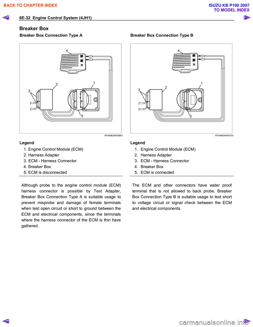
Breaker Box
Breaker Box Connection Type A
RTW 66ESH003601
Legend
1. Engine Control Module (ECM)
2. Harness Adapter
3. ECM - Harness Connector
4. Breaker Box
5. ECM is disconnected
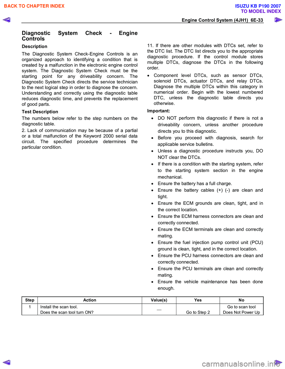
Breaker Box Connection Type B
RTW 66ESH003701
Legend
1. Engine Control Module (ECM)
2. Harness Adapter
3. ECM - Harness Connector
4. Breaker Box
5. ECM is connected
Although probe to the engine control module (ECM)
harness connector is possible by Test Adapter,
Breaker Box Connection Type A is suitable usage to
prevent misprobe and damage of female terminals
when test open circuit or short to ground between the
ECM and electrical components, since the terminals
where the harness connector of the ECM is thin have
gathered.
The ECM and other connectors have water proof
terminal that is not allowed to back probe. Breaker
Box Connection Type B is suitable usage to test short
to voltage circuit or signal check between the ECM
and electrical components.
BACK TO CHAPTER INDEX
TO MODEL INDEX
ISUZU KB P190 2007
Page 1067 of 6020

Engine Control System (4JH1) 6E-33
Diagnostic System Check - Engine
Controls
Description
The Diagnostic System Check-Engine Controls is an
organized approach to identifying a condition that is
created by a malfunction in the electronic engine control
system. The Diagnostic System Check must be the
starting point for any driveability concern. The
Diagnostic System Check directs the service technician
to the next logical step in order to diagnose the concern.
Understanding and correctly using the diagnostic table
reduces diagnostic time, and prevents the replacement
of good parts.
Test Description
The numbers below refer to the step numbers on the
diagnostic table.
2. Lack of communication may be because of a partial
or a total malfunction of the Keyword 2000 serial data
circuit. The specified procedure determines the
particular condition.
11. If there are other modules with DTCs set, refer to
the DTC list. The DTC list directs you to the appropriate
diagnostic procedure. If the control module stores
multiple DTCs, diagnose the DTCs in the following
order.
• Component level DTCs, such as sensor DTCs,
solenoid DTCs, actuator DTCs, and relay DTCs.
Diagnose the multiple DTCs within this category in
numerical order. Begin with the lowest numbered
DTC, unless the diagnostic table directs you
otherwise.
Important:
• DO NOT perform this diagnostic if there is not a
driveability concern, unless another procedure
directs you to this diagnostic.
• Before you proceed with diagnosis, search fo
r
applicable service bulletins.
• Unless a diagnostic procedure instructs you, DO
NOT clear the DTCs.
• If there is a condition with the starting system, refe
r
to the starting system section in the engine
mechanical.
• Ensure the battery has a full charge.
• Ensure the battery cables (+) (-) are clean and
tight.
• Ensure the ECM grounds are clean, tight, and in
the correct location.
• Ensure the ECM harness connectors are clean and
correctly connected.
• Ensure the ECM terminals are clean and correctl
y
mating.
• Ensure the fuel injection pump control unit (PCU)
ground is clean, tight, and in the correct location.
• Ensure the PCU harness connectors are clean and
correctly connected.
• Ensure the PCU terminals are clean and correctl
y
mating.
• Ensure the vehicle maintenance has been done
enough.
Step Action Value(s) Yes No
1 Install the scan tool.
Does the scan tool turn ON?
Go to Step 2 Go to scan tool
Does Not Power Up
BACK TO CHAPTER INDEX
TO MODEL INDEX
ISUZU KB P190 2007