2007 ISUZU KB P190 engine oil
[x] Cancel search: engine oilPage 3317 of 6020
Engine Management – V6 – Diagnostics Page 6C1-2–39
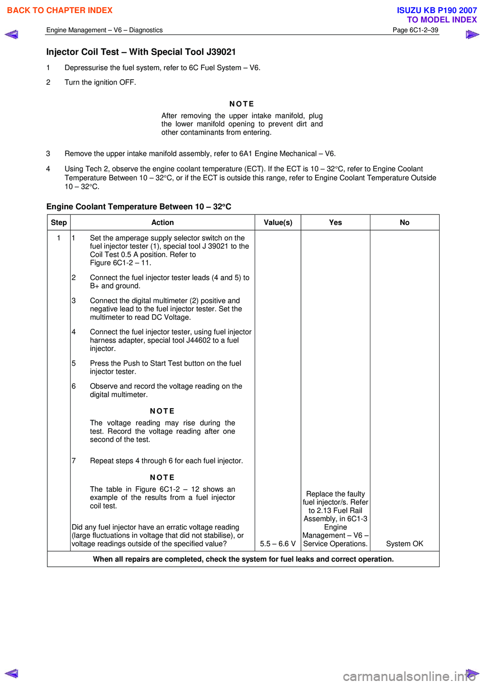
Injector Coil Test – With Special Tool J39021
1 Depressurise the fuel system, refer to 6C Fuel System – V6.
2 Turn the ignition OFF.
NOTE
After removing the upper intake manifold, plug
the lower manifold opening to prevent dirt and
other contaminants from entering.
3 Remove the upper intake manifold assembly, refer to 6A1 Engine Mechanical – V6.
4 Using Tech 2, observe the engine coolant temperature (ECT). If the ECT is 10 – 32 °C, refer to Engine Coolant
Temperature Between 10 – 32 °C, or if the ECT is outside this range, refer to Engine Coolant Temperature Outside
10 – 32 °C.
Engine Coolant Temperature Between 10 – 32 °
°°
°
C
Step Action Value(s) Yes No
1 1 Set the amperage supply selector switch on the
fuel injector tester (1), special tool J 39021 to the
Coil Test 0.5 A position. Refer to
Figure 6C1-2 – 11.
2 Connect the fuel injector tester leads (4 and 5) to B+ and ground.
3 Connect the digital multimeter (2) positive and negative lead to the fuel injector tester. Set the
multimeter to read DC Voltage.
4 Connect the fuel injector tester, using fuel injector harness adapter, special tool J44602 to a fuel
injector.
5 Press the Push to Start Test button on the fuel injector tester.
6 Observe and record the voltage reading on the digital multimeter.
NOTE
The voltage reading may rise during the
test. Record the voltage reading after one
second of the test.
7 Repeat steps 4 through 6 for each fuel injector. NOTE
The table in Figure 6C1-2 – 12 shows an
example of the results from a fuel injector
coil test.
Did any fuel injector have an erratic voltage reading
(large fluctuations in voltage that did not stabilise), or
voltage readings outside of the specified value? 5.5 – 6.6 V Replace the faulty
fuel injector/s. Refer to 2.13 Fuel Rail
Assembly, in 6C1-3 Engine
Management – V6 – Service Operations. System OK
When all repairs are completed, check the system for fuel leaks and correct operation.
BACK TO CHAPTER INDEX
TO MODEL INDEX
ISUZU KB P190 2007
Page 3318 of 6020

Engine Management – V6 – Diagnostics Page 6C1-2–40
Engine Coolant Temperature Outside 10 – 32°
°°
°
C
Step Action Value(s) Yes No
1 1 Set the amperage supply selector switch on the
fuel injector tester (1), special tool J 39021 to the
Coil Test 0.5 A position. Refer to
Figure 6C1-2 – 11.
2 Connect the fuel injector tester leads (4 and 5) to B+ and ground.
3 Connect the digital multimeter (2) positive and negative lead to the fuel injector tester. Set the
multimeter to read DC Voltage.
4 Connect the fuel injector tester, using injector harness adapter, special tool J44602 to a fuel
injector.
5 Press the Push to Start Test button on the fuel injector tester.
6 Observe and record the voltage reading on the digital multimeter.
NOTE
The voltage reading may rise during the
test. Record the voltage reading after one
second of the test.
7 Repeat steps 4 through 6 for each fuel injector.
8 Identify the highest voltage reading recorded from the six fuel injectors tested that is 9.5 V or less.
NOTE
Disregard those voltage readings that are
greater than 9.5 V. Voltage readings greater
than 9.5 V indicate a faulty fuel injector.
9 Subtract the remaining voltage readings recorded in Step 8, from the highest voltage reading.
Are any of the values recorded in Step 9 greater than
the specified value? 0.6 V
Go to Step 2 System OK
2 1 Replace any fuel injector that has any of the
following:
− a subtracted value exceeding 0.6 V,
− an initial reading greater than 9.5 V, and
− an erratic reading.
NOTE
The table in Figure 6C1-2 – 13 shows an
example of the results from a fuel injector
coil test.
Has the repair been completed? – System OK. –
When all repairs are completed, check the system for fuel leaks and correct operation.
BACK TO CHAPTER INDEX
TO MODEL INDEX
ISUZU KB P190 2007
Page 3319 of 6020
Engine Management – V6 – Diagnostics Page 6C1-2–41
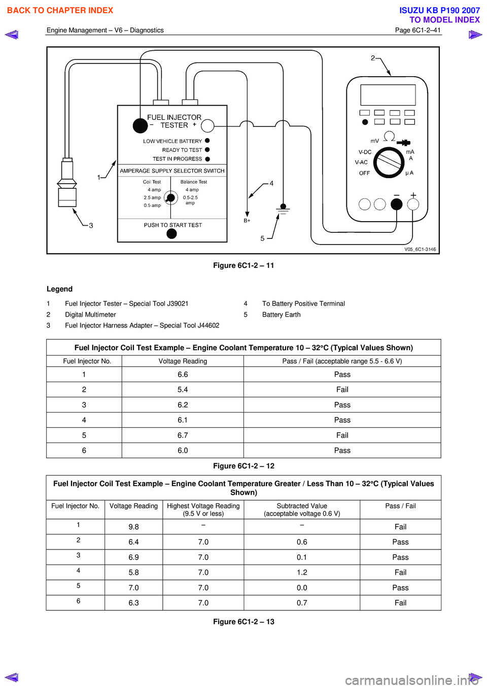
Figure 6C1-2 – 11
Legend
1 Fuel Injector Tester – Special Tool J39021
2 Digital Multimeter
3 Fuel Injector Harness Adapter – Special Tool J44602 4 To Battery Positive Terminal
5 Battery Earth
Fuel Injector Coil Test Example – Engine Coolant Temperature 10 – 32 °
°°
°
C (Typical Values Shown)
Fuel Injector No. Voltage Reading Pass / Fail (acceptable range 5.5 - 6.6 V)
1 6.6 Pass
2 5.4 Fail
3 6.2 Pass
4 6.1 Pass
5 6.7 Fail
6 6.0 Pass
Figure 6C1-2 – 12
Fuel Injector Coil Test Example – Engine Coolant Temperature Greater / Less Than 10 – 32 °
°°
°
C (Typical Values
Shown)
Fuel Injector No. Voltage Reading Highest Voltage Reading (9.5 V or less) Subtracted Value
(acceptable voltage 0.6 V) Pass / Fail
1 9.8 – – Fail
2 6.4 7.0 0.6 Pass
3 6.9 7.0 0.1 Pass
4 5.8 7.0 1.2 Fail
5 7.0 7.0 0.0 Pass
6 6.3 7.0 0.7 Fail
Figure 6C1-2 – 13
BACK TO CHAPTER INDEX
TO MODEL INDEX
ISUZU KB P190 2007
Page 3320 of 6020
Engine Management – V6 – Diagnostics Page 6C1-2–42
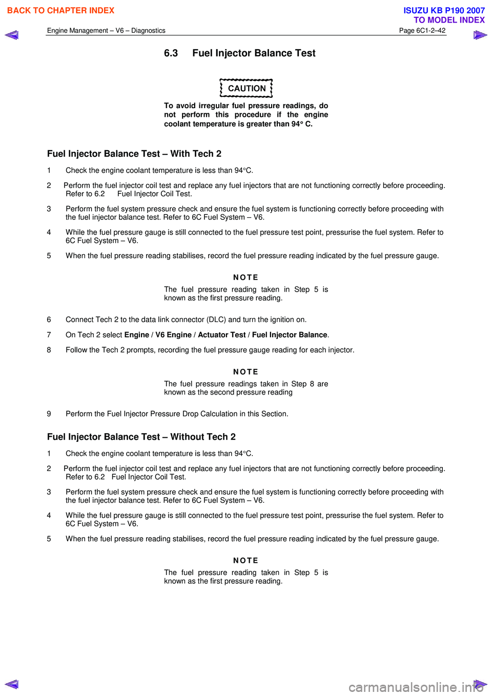
6.3 Fuel Injector Balance Test
To avoid irregular fuel pressure readings, do
not perform this procedure if the engine
coolant temperature is greater than 94 °
°°
°
C.
Fuel Injector Balance Test – With Tech 2
1 Check the engine coolant temperature is less than 94 °C.
2 Perform the fuel injector coil test and replace any fuel injectors that are not functioning correctly before proceeding. Refer to 6.2 Fuel Injector Coil Test.
3 Perform the fuel system pressure check and ensure the fuel system is functioning correctly before proceeding with the fuel injector balance test. Refer to 6C Fuel System – V6.
4 W hile the fuel pressure gauge is still connected to the fuel pressure test point, pressurise the fuel system. Refer to 6C Fuel System – V6.
5 W hen the fuel pressure reading stabilises, record the fuel pressure reading indicated by the fuel pressure gauge.
NOTE
The fuel pressure reading taken in Step 5 is
known as the first pressure reading.
6 Connect Tech 2 to the data link connector (DLC) and turn the ignition on.
7 On Tech 2 select Engine / V6 Engine / Actuator Test / Fuel Injector Balance .
8 Follow the Tech 2 prompts, recording the fuel pressure gauge reading for each injector.
NOTE
The fuel pressure readings taken in Step 8 are
known as the second pressure reading
9 Perform the Fuel Injector Pressure Drop Calculation in this Section.
Fuel Injector Balance Test – Without Tech 2
1 Check the engine coolant temperature is less than 94 °C.
2 Perform the fuel injector coil test and replace any fuel injectors that are not functioning correctly before proceeding. Refer to 6.2 Fuel Injector Coil Test.
3 Perform the fuel system pressure check and ensure the fuel system is functioning correctly before proceeding with the fuel injector balance test. Refer to 6C Fuel System – V6.
4 W hile the fuel pressure gauge is still connected to the fuel pressure test point, pressurise the fuel system. Refer to 6C Fuel System – V6.
5 W hen the fuel pressure reading stabilises, record the fuel pressure reading indicated by the fuel pressure gauge.
NOTE
The fuel pressure reading taken in Step 5 is
known as the first pressure reading.
BACK TO CHAPTER INDEX
TO MODEL INDEX
ISUZU KB P190 2007
Page 3325 of 6020
Engine Management – V6 – Diagnostics Page 6C1-2–47
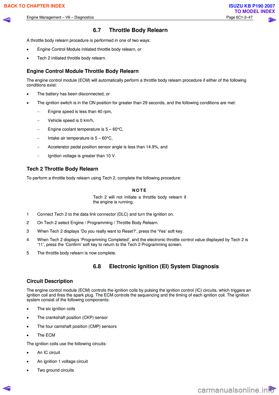
6.7 Throttle Body Relearn
A throttle body relearn procedure is performed in one of two ways:
• Engine Control Module initiated throttle body relearn, or
• Tech 2 initiated throttle body relearn.
Engine Control Module Throttle Body Relearn
The engine control module (ECM) will automatically perform a throttle body relearn procedure if either of the following
conditions exist:
• The battery has been disconnected, or
• The ignition switch is in the ON position for greater than 29 seconds, and the following conditions are met:
− Engine speed is less than 40 rpm,
− Vehicle speed is 0 km/h,
− Engine coolant temperature is 5 – 60°C,
− Intake air temperature is 5 – 60°C,
− Accelerator pedal position sensor angle is less than 14.9%, and
− Ignition voltage is greater than 10 V.
Tech 2 Throttle Body Relearn
To perform a throttle body relearn using Tech 2, complete the following procedure:
NOTE
Tech 2 will not initiate a throttle body relearn if
the engine is running.
1 Connect Tech 2 to the data link connector (DLC) and turn the ignition on.
2 On Tech 2 select Engine / Programming / Throttle Body Relearn.
3 W hen Tech 2 displays ‘Do you really want to Reset?’, press the ‘Yes’ soft key.
4 W hen Tech 2 displays ‘Programming Completed’, and the electronic throttle control value displayed by Tech 2 is ‘11’, press the ‘Confirm’ soft key to return to the Tech 2 Programming screen.
5 The throttle body relearn is now complete.
6.8 Electronic Ignition (EI) System Diagnosis
Circuit Description
The engine control module (ECM) controls the ignition coils by pulsing the ignition control (IC) circuits, which triggers an
ignition coil and fires the spark plug. The ECM controls the sequencing and the timing of each ignition coil. The ignition
system consist of the following components:
• The six ignition coils
• The crankshaft position (CKP) sensor
• The four camshaft position (CMP) sensors
• The ECM
The ignition coils use the following circuits:
• An IC circuit
• An ignition 1 voltage circuit
• Two ground circuits
BACK TO CHAPTER INDEX
TO MODEL INDEX
ISUZU KB P190 2007
Page 3326 of 6020
Engine Management – V6 – Diagnostics Page 6C1-2–48
Additional Information
• Use the J 35616-B Connector Test Adapter Kit for any test that requires probing the ECM harness connector or a
component harness connector.
• Inspect the ignition coils for aftermarket devices. An aftermarket device connected to the ignition coil circuits, may
cause a condition with the ignition coils.
• For an intermittent fault condition, refer to 5.2 Intermittent Fault Conditions in this Section.
• To assist diagnosis, refer to 3 W iring Diagrams and Connector Charts in this Section, for the system wiring
diagram and connector charts.
Test Description
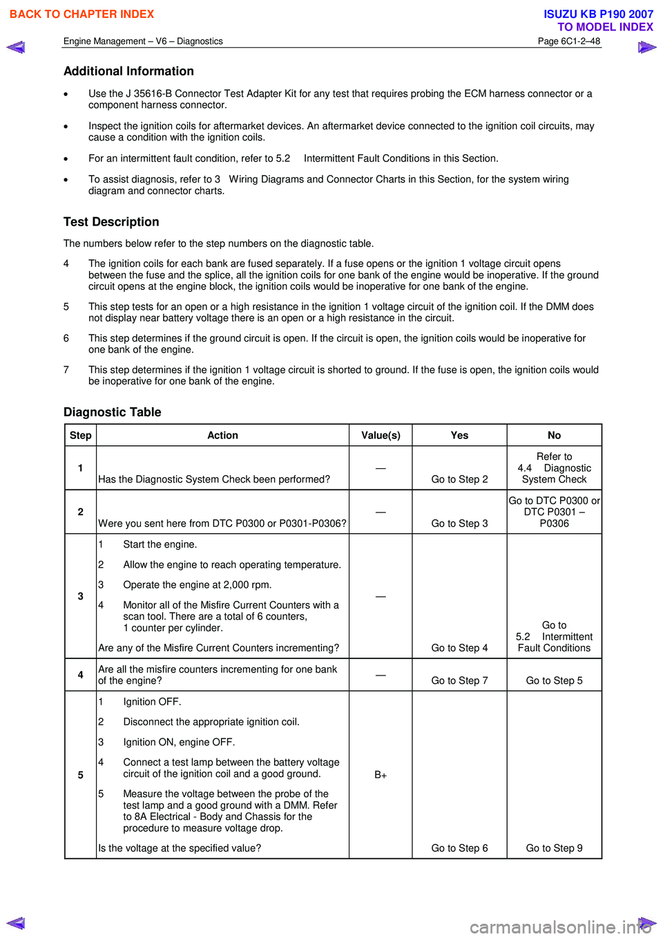
The numbers below refer to the step numbers on the diagnostic table.
4 The ignition coils for each bank are fused separately. If a fuse opens or the ignition 1 voltage circuit opens between the fuse and the splice, all the ignition coils for one bank of the engine would be inoperative. If the ground
circuit opens at the engine block, the ignition coils would be inoperative for one bank of the engine.
5 This step tests for an open or a high resistance in the ignition 1 voltage circuit of the ignition coil. If the DMM does not display near battery voltage there is an open or a high resistance in the circuit.
6 This step determines if the ground circuit is open. If the circuit is open, the ignition coils would be inoperative for one bank of the engine.
7 This step determines if the ignition 1 voltage circuit is shorted to ground. If the fuse is open, the ignition coils would be inoperative for one bank of the engine.
Diagnostic Table
Step Action Value(s) Yes No
1
Has the Diagnostic System Check been performed? —
Go to Step 2 Refer to
4.4 Diagnostic System Check
2 W ere you sent here from DTC P0300 or P0301-P0306? —
Go to Step 3 Go to DTC P0300 or
DTC P0301 – P0306
3 1 Start the engine.
2 Allow the engine to reach operating temperature.
3 Operate the engine at 2,000 rpm.
4 Monitor all of the Misfire Current Counters with a scan tool. There are a total of 6 counters,
1 counter per cylinder.
Are any of the Misfire Current Counters incrementing? —
Go to Step 4 Go to
5.2 Intermittent Fault Conditions
4 Are all the misfire counters incrementing for one bank
of the engine? —
Go to Step 7 Go to Step 5
5 1 Ignition OFF.
2 Disconnect the appropriate ignition coil.
3 Ignition ON, engine OFF.
4 Connect a test lamp between the battery voltage circuit of the ignition coil and a good ground.
5 Measure the voltage between the probe of the test lamp and a good ground with a DMM. Refer
to 8A Electrical - Body and Chassis for the
procedure to measure voltage drop.
Is the voltage at the specified value? B+
Go to Step 6 Go to Step 9
BACK TO CHAPTER INDEX
TO MODEL INDEX
ISUZU KB P190 2007
Page 3327 of 6020

Engine Management – V6 – Diagnostics Page 6C1-2–49
6 1 Connect the test lamp between the battery
voltage circuit of the ignition coil and to each
ground circuit of the ignition coil.
Does the test lamp illuminate at each ground circuit? —
Go to Step 8 Go to Step 10
7 1 Test the battery voltage circuit for an open or high
resistance at the splice of the affected bank of
ignition coils. Refer to 8A Electrical - Body and
Chassis for circuit testing procedures.
Did you find and correct the condition? —
Go to Step 12 Go to Step 10
8 1 Test for an intermittent and for a poor connection
at the ignition coil. Refer to 8A Electrical - Body
and Chassis for circuit testing procedures.
Did you find and correct the condition? —
Go to Step 12 Go to Step 11
9 NOTE
The battery voltage circuit is shared with
other components. Disconnecting a
component on the shared battery voltage
circuit may isolate a shorted component.
Review the electrical schematic and
diagnose the shared circuits and
components.
1 Repair a short to ground, an open or high resistance in the ignition 1 voltage circuit. Refer to
Refer to 8A Electrical - Body and Chassis for
wiring repair procedures.
2 Replace the fuse as necessary.
Did you complete the repair? —
Go to Step 12 —
10 1 Repair the open or high resistance in the ground
circuit. Refer to 8A Electrical - Body and Chassis
for wiring repair procedures.
Did you complete the repair? —
Go to Step 12 —
11 1 Replace the ignition coil. Refer to 2.15 Ignition
Coils, in 6C1-3 Engine Management – V6 –
Service Operations.
Did you complete the replacement? —
Go to Step 12 —
12 1 Connect all disconnected components.
2 Use Tech 2 to clear the DTC/s.
3 Start the engine.
4 Observe the Capture Info with Tech 2.
Do any of the misfire counters increment? —
Go to Step 2 Go to Step 13
13 1 Using Tech 2, select the DTC display function.
Does Tech 2 display any DTCs? — Go to the
appropriate DTC
Table in this Section System OK
When all diagnosis and repairs are completed, clear all DTCs and verify correct operation
BACK TO CHAPTER INDEX
TO MODEL INDEX
ISUZU KB P190 2007
Page 3331 of 6020
Engine Management – V6 – Diagnostics Page 6C1-2–53
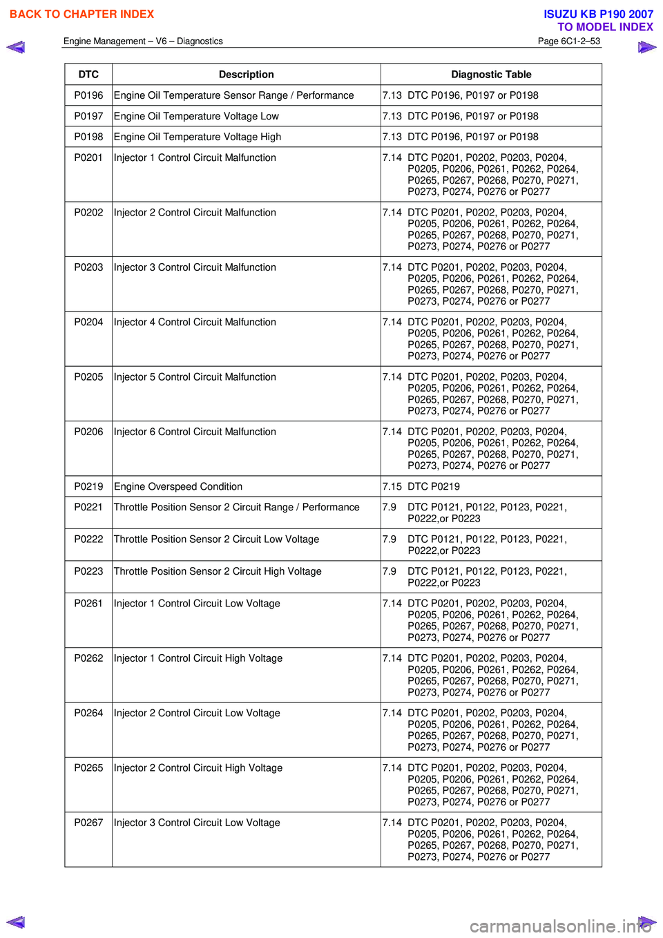
DTC Description Diagnostic Table
P0196 Engine Oil Temperature Sensor Range / Performance 7.13 DTC P0196, P0197 or P0198
P0197 Engine Oil Temperature Voltage Low 7.13 DTC P0196, P0197 or P0198
P0198 Engine Oil Temperature Voltage High 7.13 DTC P0196, P0197 or P0198
P0201 Injector 1 Control Circuit Malfunction 7.14 DTC P0201, P0202, P0203, P0204,
P0205, P0206, P0261, P0262, P0264,
P0265, P0267, P0268, P0270, P0271,
P0273, P0274, P0276 or P0277
P0202 Injector 2 Control Circuit Malfunction 7.14 DTC P0201, P0202, P0203, P0204,
P0205, P0206, P0261, P0262, P0264,
P0265, P0267, P0268, P0270, P0271,
P0273, P0274, P0276 or P0277
P0203 Injector 3 Control Circuit Malfunction 7.14 DTC P0201, P0202, P0203, P0204,
P0205, P0206, P0261, P0262, P0264,
P0265, P0267, P0268, P0270, P0271,
P0273, P0274, P0276 or P0277
P0204 Injector 4 Control Circuit Malfunction 7.14 DTC P0201, P0202, P0203, P0204,
P0205, P0206, P0261, P0262, P0264,
P0265, P0267, P0268, P0270, P0271,
P0273, P0274, P0276 or P0277
P0205 Injector 5 Control Circuit Malfunction 7.14 DTC P0201, P0202, P0203, P0204,
P0205, P0206, P0261, P0262, P0264,
P0265, P0267, P0268, P0270, P0271,
P0273, P0274, P0276 or P0277
P0206 Injector 6 Control Circuit Malfunction 7.14 DTC P0201, P0202, P0203, P0204,
P0205, P0206, P0261, P0262, P0264,
P0265, P0267, P0268, P0270, P0271,
P0273, P0274, P0276 or P0277
P0219 Engine Overspeed Condition 7.15 DTC P0219
P0221 Throttle Position Sensor 2 Circuit Range / Performance 7.9 DTC P0121, P0122, P0123, P0221,
P0222,or P0223
P0222 Throttle Position Sensor 2 Circuit Low Voltage 7.9 DTC P0121, P0122, P0123, P0221,
P0222,or P0223
P0223 Throttle Position Sensor 2 Circuit High Voltage 7.9 DTC P0121, P0122, P0123, P0221,
P0222,or P0223
P0261 Injector 1 Control Circuit Low Voltage 7.14 DTC P0201, P0202, P0203, P0204,
P0205, P0206, P0261, P0262, P0264,
P0265, P0267, P0268, P0270, P0271,
P0273, P0274, P0276 or P0277
P0262 Injector 1 Control Circuit High Voltage 7.14 DTC P0201, P0202, P0203, P0204,
P0205, P0206, P0261, P0262, P0264,
P0265, P0267, P0268, P0270, P0271,
P0273, P0274, P0276 or P0277
P0264 Injector 2 Control Circuit Low Voltage 7.14 DTC P0201, P0202, P0203, P0204,
P0205, P0206, P0261, P0262, P0264,
P0265, P0267, P0268, P0270, P0271,
P0273, P0274, P0276 or P0277
P0265 Injector 2 Control Circuit High Voltage 7.14 DTC P0201, P0202, P0203, P0204,
P0205, P0206, P0261, P0262, P0264,
P0265, P0267, P0268, P0270, P0271,
P0273, P0274, P0276 or P0277
P0267 Injector 3 Control Circuit Low Voltage 7.14 DTC P0201, P0202, P0203, P0204,
P0205, P0206, P0261, P0262, P0264,
P0265, P0267, P0268, P0270, P0271,
P0273, P0274, P0276 or P0277
BACK TO CHAPTER INDEX
TO MODEL INDEX
ISUZU KB P190 2007