2007 ISUZU KB P190 engine oil
[x] Cancel search: engine oilPage 3211 of 6020
Fuel System – V6 Page 6C – 9
A small amount of fuel may be released when
connecting the fuel pressure gauge to the fuel
pressure test point. Cover the fittings with a
shop towel to absorb any fuel spillage before
connecting the fuel pressure gauge. After the
fuel pressure test procedure, place the soiled
towel in an approved container for disposal.
3 At the fuel pressure test point, remove the Schrader valve sealing cap.
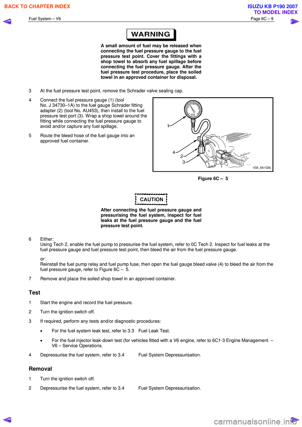
4 Connect the fuel pressure gauge (1) (tool No. J 34730–1A) to the fuel gauge Schrader fitting
adapter (2) (tool No. AU453), then install to the fuel
pressure test port (3). W rap a shop towel around the
fitting while connecting the fuel pressure gauge to
avoid and/or capture any fuel spillage.
5 Route the bleed hose of the fuel gauge into an approved fuel container.
Figure 6C – 5
After connecting the fuel pressure gauge and
pressurising the fuel system, inspect for fuel
leaks at the fuel pressure gauge and the fuel
pressure test point.
6 Either: Using Tech 2, enable the fuel pump to pressurise the fuel system, refer to 0C Tech 2. Inspect for fuel leaks at the
fuel pressure gauge and fuel pressure test point, then bleed the air from the fuel pressure gauge.
or: Reinstall the fuel pump relay and fuel pump fuse, then open the fuel gauge bleed valve (4) to bleed the air from the
fuel pressure gauge, refer to Figure 6C – 5.
7 Remove and place the soiled shop towel in an approved container.
Test
1 Start the engine and record the fuel pressure.
2 Turn the ignition switch off.
3 If required, perform any tests and/or diagnostic procedures:
• For the fuel system leak test, refer to 3.3 Fuel Leak Test.
• For the fuel injector leak-down test (for vehicles fitted with a V6 engine, refer to 6C1-3 Engine Management –
V6 – Service Operations.
4 Depressurise the fuel system, refer to 3.4 Fuel System Depressurisation.
Removal
1 Turn the ignition switch off.
2 Depressurise the fuel system, refer to 3.4 Fuel System Depressurisation.
BACK TO CHAPTER INDEX
TO MODEL INDEX
ISUZU KB P190 2007
Page 3212 of 6020
Fuel System – V6 Page 6C – 10
After relieving the fuel system pressure, a
small amount of fuel may be released when
servicing the fuel lines or connections. Cover
the fittings with a shop towel before
disconnecting. This catches any leaking fuel.
Place the soiled towel in an approved
container when disconnection is completed.
3 W rap a shop towel around the fuel pressure test point to absorb any fuel spillage.
4 Remove the fuel pressure gauge and drain any fuel remaining in the fuel pressure gauge into an approved fuel container.
5 Remove the soiled shop towel and place in an approved container.
6 Repressurise the fuel system, refer to 3.4 Fuel System Depressurisation.
7 Road-test the vehicle and check for correct operation.
3.3 Fuel Leak Test
After installing any fuel system component
and before starting the engine, check the fuel
system for leaks.
NOTE
For the fuel injector leak-down test (for vehicles
fitted with a V6 engine), refer to 6C1-3 Engine
Management – V6 – Service Operations.
1 Turn the ignition switch on for two seconds.
2 Turn the ignition switch off for 10 seconds.
3 Turn the ignition switch on.
4 Check for fuel leaks, particularly at points marked �z (that is, quick-connect fittings, fuel rails, fuel injectors,
Schrader valve and evaporative emission control canister purge solenoid, refer to Figure 6C – 6.
BACK TO CHAPTER INDEX
TO MODEL INDEX
ISUZU KB P190 2007
Page 3214 of 6020
Fuel System – V6 Page 6C – 12
A small amount of fuel may be released when
pressing on the Schrader valve. Cover the
fitting with a shop towel to absorb any fuel
spillage before removing the Schrader valve
sealing cap. Place the soiled towel in an
approved container for disposal.
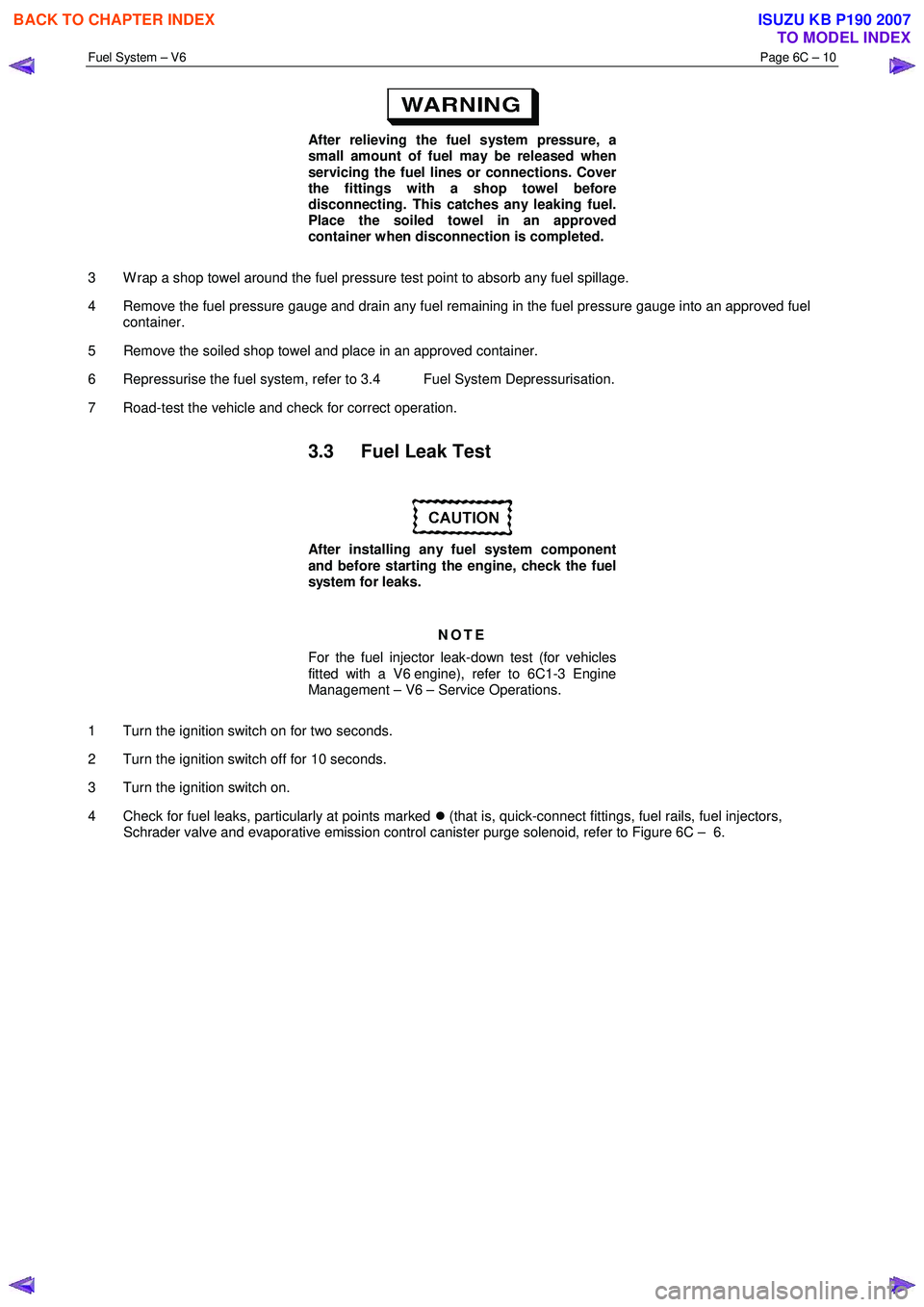
7 At the fuel pressure test point (2), remove the Schrader valve sealing cap (1), refer to Figure 6C – 7.
Figure 6C – 7
Legend
1 Schrader Valve Sealing Cap
2 Pressure Test Point 3 Schrader Valve
Wear safety glasses when performing the fuel
pressure relief procedure.
8 Place a shop towel around the Schrader valve to soak up the expelled petrol.
9 Use a small screwdriver to press the Schrader valve down (3).
10 Remove the soiled shop towel and place in an approved container.
Repressurise
1 Reinstall the fuel pump relay and fuel pump fuse.
2 Perform the following procedure to inspect for leaks at the fuel pressure test point: a Turn the ignition switch on for two seconds.
b Turn the ignition switch off for 10 seconds.
c Turn the ignition switch on.
d Check for leaks at the fuel pressure test point.
3 Tighten the fuel filler cap.
4 Start the engine and recheck for leaks.
5 Reinstall the Schrader valve sealing cap.
BACK TO CHAPTER INDEX
TO MODEL INDEX
ISUZU KB P190 2007
Page 3217 of 6020
Fuel System – V6 Page 6C – 15
Reinstall
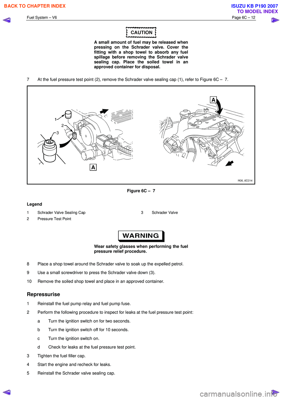
1 Apply a small amount of engine oil or light oil to the
fuel line to assist in the assembly of the connector.
NOTE
Assembly of the fuel line and quick connectors
should take place immediately after applying the
oil to prevent any dust from sticking to the
surface, which may cause the connector to leak.
Figure 6C – 12
4.2 Fuel Filter
Removal
1 Depressurize the fuel system, refer to 3.4 Fuel
System Depressurisation.
2 Disconnect the battery ground cable.
A small amount of fuel will flow out of the
fuel lines and filter when disconnected.
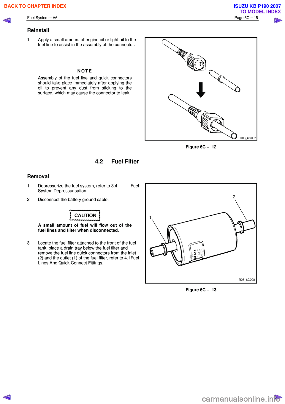
3 Locate the fuel filter attached to the front of the fuel tank, place a drain tray below the fuel filter and
remove the fuel line quick connectors from the inlet
(2) and the outlet (1) of the fuel filter, refer to 4.1 Fuel
Lines And Quick Connect Fittings.
Figure 6C – 13
BACK TO CHAPTER INDEX
TO MODEL INDEX
ISUZU KB P190 2007
Page 3244 of 6020
Engine Management – V6 – General Information Page 6C1-1–2
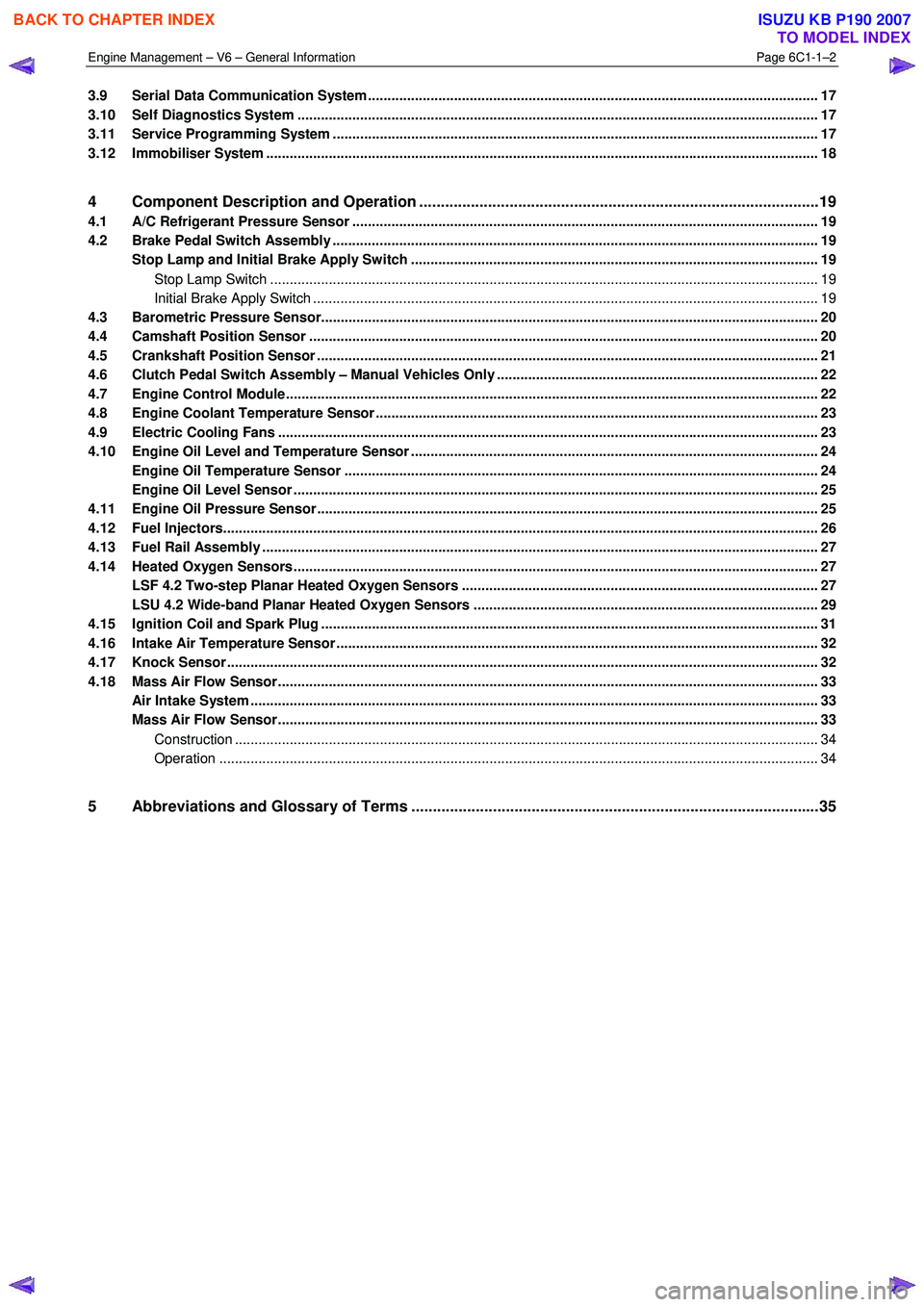
3.9 Serial Data Communication System ................................................................................................................... 17
3.10 Self Diagnostics System ..................................................................................................................................... 17
3.11 Service Programming System ..................................................................................................... ....................... 17
3.12 Immobiliser System ............................................................................................................................................. 18
4 Component Description and Operation ............................................................................................ .19
4.1 A/C Refrigerant Pressure Sensor ....................................................................................................................... 19
4.2 Brake Pedal Switch Assembly ............................................................................................................................ 19
Stop Lamp and Initial Brake Apply Switch ....................................................................................... ................. 19
Stop Lamp Switch ............................................................................................................................................ 19
Initial Brake Apply Switch ..................................................................................................... ............................ 19
4.3 Barometric Pressure Sensor..................................................................................................... .......................... 20
4.4 Camshaft Position Sensor .................................................................................................................................. 20
4.5 Crankshaft Position Sensor ................................................................................................................................ 21
4.6 Clutch Pedal Switch Assembly – Manual Vehicles Only ............................................................................ ...... 22
4.7 Engine Control Module........................................................................................................................................ 22
4.8 Engine Coolant Temperature Sensor .............................................................................................. ................... 23
4.9 Electric Cooling Fans .......................................................................................................................................... 23
4.10 Engine Oil Level and Temperature Sensor ........................................................................................ ................ 24
Engine Oil Temperature Sensor ......................................................................................................................... 24
Engine Oil Level Sensor ...................................................................................................................................... 25
4.11 Engine Oil Pressure Sensor..................................................................................................... ........................... 25
4.12 Fuel Injectors........................................................................................................................................................ 26
4.13 Fuel Rail Assembly ............................................................................................................. ................................. 27
4.14 Heated Oxygen Sensors .......................................................................................................... ............................ 27
LSF 4.2 Two-step Planar Heated Oxygen Sensors .................................................................................. ......... 27
LSU 4.2 Wide-band Planar Heated Oxygen Sensors ................................................................................. ....... 29
4.15 Ignition Coil and Spark Plug ............................................................................................................................... 31
4.16 Intake Air Temperature Sensor .................................................................................................. ......................... 32
4.17 Knock Sensor ....................................................................................................................................................... 32
4.18 Mass Air Flow Sensor........................................................................................................... ............................... 33
Air Intake System ................................................................................................................................................. 33
Mass Air Flow Sensor........................................................................................................... ............................... 33
Construction ..................................................................................................................................................... 34
Operation ......................................................................................................................................................... 34
5 Abbreviations and Glossary of Terms ............................................................................................ ...35
BACK TO CHAPTER INDEX
TO MODEL INDEX
ISUZU KB P190 2007
Page 3245 of 6020
Engine Management – V6 – General Information Page 6C1-1–3
1 General Information
The V6 engine management system
incorporates functions and components that
could cause personal injury or vehicle
damage. Refer to 6C1-2 Engine Management –
V6 – Diagnostics, and 6C1-3 Engine
Management – V6 – Service Operations,
before attempting any diagnosis or repairs.
1.1 Introduction
The V6 engine management system is designed to improve engine performance and increase vehicle safety while
meeting the stringent Euro 3 vehicle emission standard. This is achieved by the introduction of the following engine
management sub-systems and components:
• Throttle actuator control (TAC) System – the TAC system allows the engine control module (ECM) to electronically
control the throttle plate opening eliminating the need for the following components:
• mechanical link between the throttle plate and accelerator pedal,
• cruise control module, and
• idle air control motor.
Refer to 3.5 Throttle Actuator Control System for details of the TAC System operation and to 3.6 Cruise Control System for details of the cruise control operation.
This feature results in improved driveability, better fuel economy and emission control.
• W ide band heated oxygen sensor provides a more accurate measurement of the oxygen concentration in the
exhaust gas. Refer to 4.14 Heated Oxygen Sensors.
• Dual spray fuel injectors are now used. The use of this spray pattern is used in engines with two intake valves per
cylinder. The dual spray is achieved by having two openings in the spray orifice disc that are arranged in such a
way that two fuel sprays result, being aimed at each intake valve port. Refer to 4.12 Fuel Injectors.
• Pencil Coil – allows the ignition coil to be fitted directly on the spark plug eliminating the need for spark plug wires.
Refer to 4.15 Ignition Coil and Spark Plug.
The engine management system has a self diagnostic capability, as well as connections to enable diagnosis of faults. If
the ECM recognises operational problems it can alert the driver via the malfunction indicator lamp (MIL) in the instrument
cluster. The ECM also interfaces with other systems in the vehicle as required.
For further information on the air-conditioning system refer to 2A Heater and Air-conditioning,
For the location of fuses, fusible links and relays, refer to 8A Electrical-Body and Chassis.
1.2 Emission Control
ADR 79/01 Emissions Standards
MY2006 I190 Rodeo has been configured to comply with Australian Design Rule 79/01, that adopts the technical
requirements of the European Council Directive 98/69/EC. Commonly referred to as “Euro 3”, the new legislation
modifies the exhaust emissions, compared to the existing ADR 37/01 (or ‘Euro 2’) vehicle emissions standards.
Australian Design Rule 79/01 implements the 'Euro 3' exhaust and evaporative emissions requirements for petrol fuelled
passenger cars, forward control vehicles and passenger off-road vehicles with a gross vehicle mass (GVM) up to 3.5
tonnes. All new vehicles within these categories and first registered from January 1, 2006 must comply with ADR 79/01.
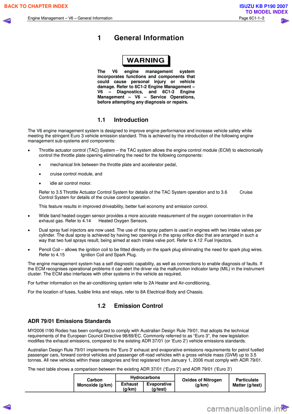
The next table shows a comparison between the existing ADR 37/01 (‘Euro 2’) and ADR 79/01 (‘Euro 3’) Hydrocarbons
Carbon
Monoxide (g/km) Exhaust
(g/km) Evaporative
(g/test) Oxides of Nitrogen
(g/km) Particulate
Matter (g/test)
BACK TO CHAPTER INDEX
TO MODEL INDEX
ISUZU KB P190 2007
Page 3248 of 6020
Engine Management – V6 – General Information Page 6C1-1–6
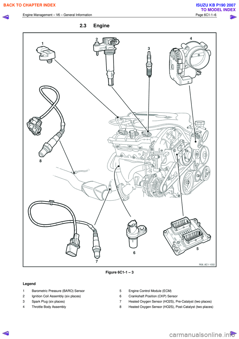
2.3 Engine
Figure 6C1-1 – 3
Legend
1 Barometric Pressure (BARO) Sensor
2 Ignition Coil Assembly (six places)
3 Spark Plug (six places)
4 Throttle Body Assembly 5 Engine Control Module (ECM)
6 Crankshaft Position (CKP) Sensor
7 Heated Oxygen Sensor (HO2S), Pre-Catalyst (two places)
8 Heated Oxygen Sensor (HO2S), Post-Catalyst (two places)
BACK TO CHAPTER INDEX
TO MODEL INDEX
ISUZU KB P190 2007
Page 3249 of 6020
Engine Management – V6 – General Information Page 6C1-1–7
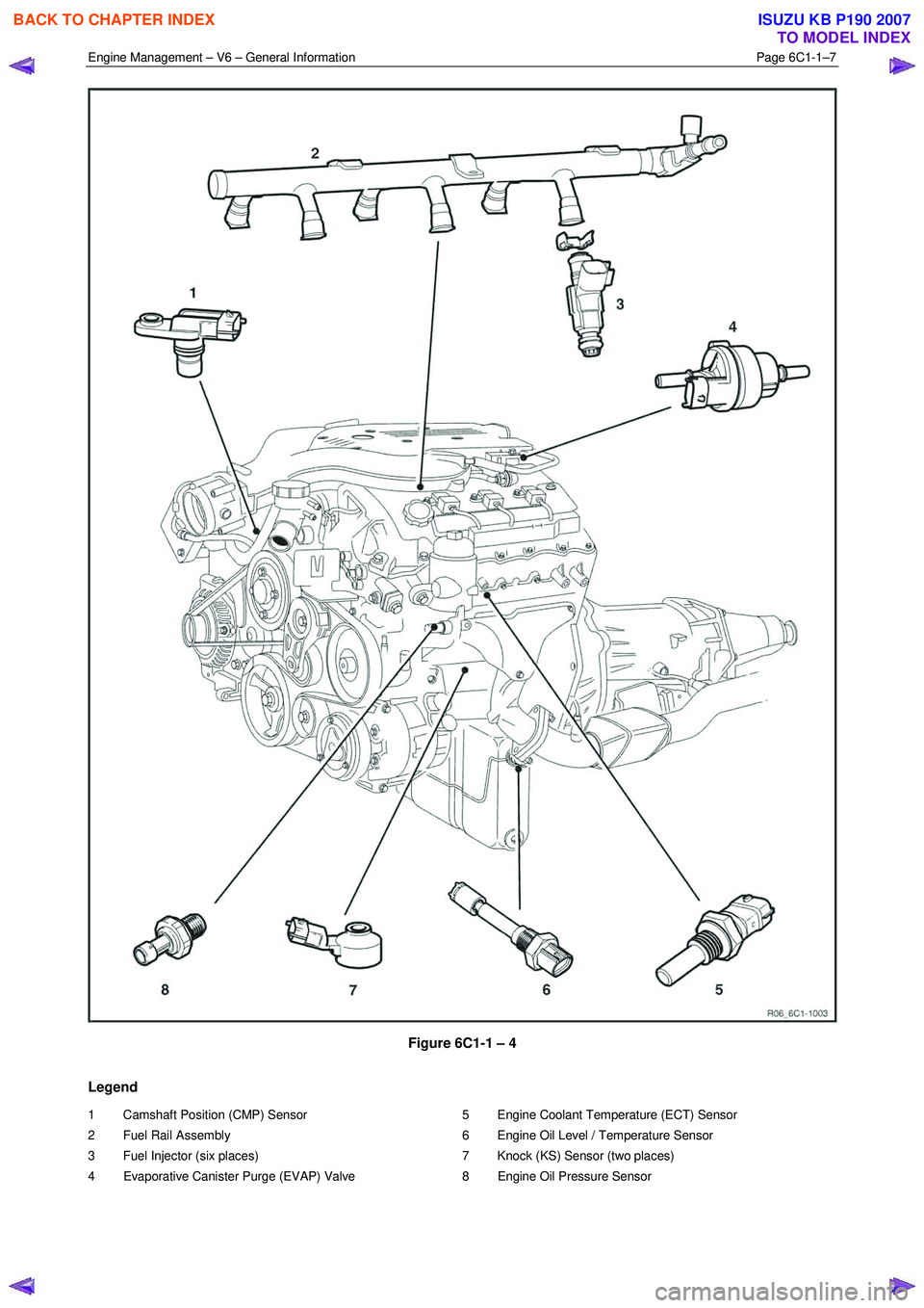
Figure 6C1-1 – 4
Legend
1 Camshaft Position (CMP) Sensor
2 Fuel Rail Assembly
3 Fuel Injector (six places)
4 Evaporative Canister Purge (EVAP) Valve 5 Engine Coolant Temperature (ECT) Sensor
6 Engine Oil Level / Temperature Sensor
7 Knock (KS) Sensor (two places)
8 Engine Oil Pressure Sensor
BACK TO CHAPTER INDEX
TO MODEL INDEX
ISUZU KB P190 2007