2007 ISUZU KB P190 engine oil
[x] Cancel search: engine oilPage 3133 of 6020
Engine Mechanical – V6 Page 6A1–356
Page 6A1–356
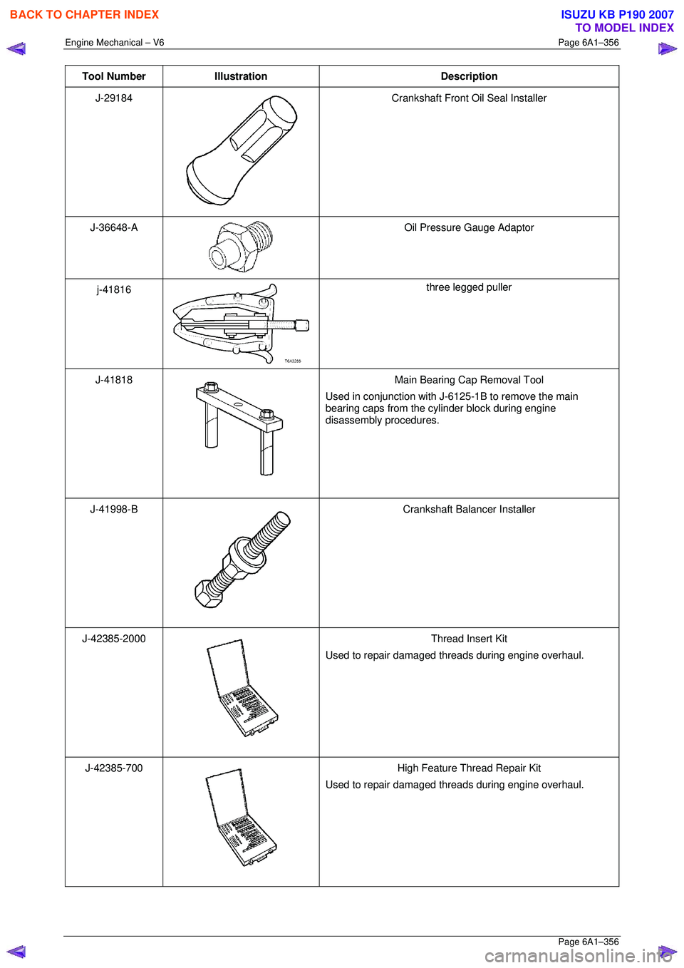
Tool Number Illustration Description
J-29184
Crankshaft Front Oil Seal Installer
J-36648-A
Oil Pressure Gauge Adaptor
j-41816
three legged puller
J-41818
Main Bearing Cap Removal Tool
Used in conjunction with J-6125-1B to remove the main
bearing caps from the cylinder block during engine
disassembly procedures.
J-41998-B
Crankshaft Balancer Installer
J-42385-2000
Thread Insert Kit
Used to repair damaged threads during engine overhaul.
J-42385-700
High Feature Thread Repair Kit
Used to repair damaged threads during engine overhaul.
BACK TO CHAPTER INDEX
TO MODEL INDEX
ISUZU KB P190 2007
Page 3137 of 6020
Engine Cooling – V6 Engine Page 6B1–2
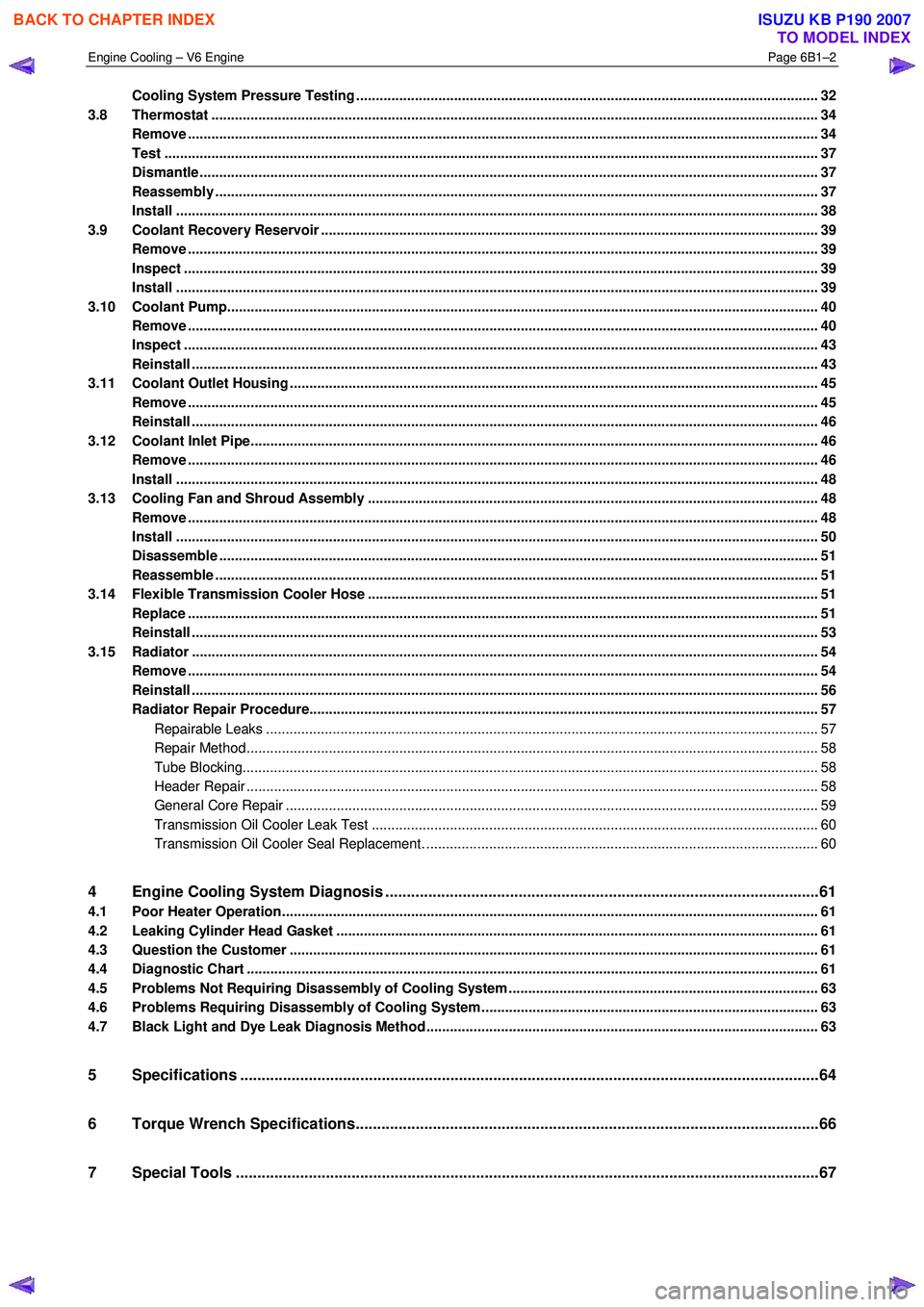
Cooling System Pressure Testing ................................................................................................ ...................... 32
3.8 Thermostat ........................................................................................................................................................... 34
Remove ................................................................................................................................................................. 34
Test ....................................................................................................................................................................... 37
Dismantle ...................................................................................................................... ........................................ 37
Reassembly .......................................................................................................................................................... 37
Install .................................................................................................................................................................... 38
3.9 Coolant Recovery Reservoir ..................................................................................................... .......................... 39
Remove ................................................................................................................................................................. 39
Inspect .................................................................................................................................................................. 39
Install .................................................................................................................................................................... 39
3.10 Coolant Pump................................................................................................................... .................................... 40
Remove ................................................................................................................................................................. 40
Inspect .................................................................................................................................................................. 43
Reinstall ................................................................................................................................................................ 43
3.11 Coolant Outlet Housing ......................................................................................................... .............................. 45
Remove ................................................................................................................................................................. 45
Reinstall ................................................................................................................................................................ 46
3.12 Coolant Inlet Pipe............................................................................................................. .................................... 46
Remove ................................................................................................................................................................. 46
Install .................................................................................................................................................................... 48
3.13 Cooling Fan and Shroud Assembly ................................................................................................ ................... 48
Remove ................................................................................................................................................................. 48
Install .................................................................................................................................................................... 50
Disassemble ......................................................................................................................................................... 51
Reassemble .......................................................................................................................................................... 51
3.14 Flexible Transmission Cooler Hose .............................................................................................. ..................... 51
Replace ................................................................................................................................................................. 51
Reinstall ................................................................................................................................................................ 53
3.15 Radiator ....................................................................................................................... ......................................... 54
Remove ......................................................................................................................... ........................................ 54
Reinstall ................................................................................................................................................................ 56
Radiator Repair Procedure...................................................................................................... ............................ 57
Repairable Leaks ............................................................................................................................................. 57
Repair Method.................................................................................................................................................. 58
Tube Blocking................................................................................................................................................... 58
Header Repair .................................................................................................................. ................................ 58
General Core Repair ............................................................................................................ ............................ 59
Transmission Oil Cooler Leak Test .............................................................................................. .................... 60
Transmission Oil Cooler Seal Replacement. ...................................................................................... .............. 60
4 Engine Cooling System Diagnosis .....................................................................................................61
4.1 Poor Heater Operation......................................................................................................................................... 61
4.2 Leaking Cylinder Head Gasket ................................................................................................... ........................ 61
4.3 Question the Customer ....................................................................................................................................... 61
4.4 Diagnostic Chart .................................................................................................................................................. 61
4.5 Problems Not Requiring Disassembly of Cooling System ........................................................................... .... 63
4.6 Problems Requiring Disassembly of Cooling System ...................................................................................... 63
4.7 Black Light and Dye Leak Diagnosis Method .................................................................................................... 63
5 Specifications .......................................................................................................................................64
6 Torque Wrench Specifications................................................................................................... .........66
7 Special Tools ........................................................................................................................................67
BACK TO CHAPTER INDEX
TO MODEL INDEX
ISUZU KB P190 2007
Page 3140 of 6020
Engine Cooling – V6 Engine Page 6B1–5
2 General Description
2.1 Radiator Assembly
The radiator has an aluminium core and is of the cross-flow design. Plastic side tanks are attached to the core by clinch
tabs. The clinch tabs are formed as part of the core assembly.
The lower frame of the radiator assembly is attached to the vehicle frame by two bolts supported in rubber mounts, pegs
are attached to the upper area of each side tank. These pegs are used to support the radiator with two rubber insert
mounting brackets.
A high temperature rubber seal is used to seal the mating surface between the core and each side tank. The seal(s)
must be replaced any time the side tank is removed from the core.
NOTE
The radiator core side tanks or transmission oil
cooler cannot be replaced separately. If there is a
fault with any of these components, the radiator
assembly must be replaced. Small core repairs
may be made using an aluminised silicon based
liquid repair agent. Refer to 3.15 Radiator in
this Section.
For vehicles with automatic transmission, a transmission oil cooler is located in the right-hand side radiator tank. The
cooler pipes from and to the transmission are connected to the oil cooler flexible hoses by means of quick connect
fittings.
The cooling fan motor is attached by three screws to the one-piece plastic fan shroud. In turn, the fan shroud is mounted
to the rear of the radiator and is located and supported by two bolts and two locating tabs. The upper clips lock the fan
shroud in place and can be released by hand to facilitate fan shroud removal. The shroud must be removed to allow fan
motor and blade assembly removal.
One harness connector is mounted to the upper section of the fan shroud allowing the fan motor and blade assemblies
to be removed individually from the shroud. The fan motor and blade is balanced as an assembly. These two
components are serviced only as a unit and are not to be separated.
The shroud, fan assembly and transmission cooler hoses can be removed and installed individually from the vehicle. For
removal and installation procedures, refer to 3.13Cooling Fan and Shroud Assembly, 3.14 Flexible Transmission
Cooler Hose and 3.15 Radiator in this Section.
BACK TO CHAPTER INDEX
TO MODEL INDEX
ISUZU KB P190 2007
Page 3143 of 6020
Engine Cooling – V6 Engine Page 6B1–8
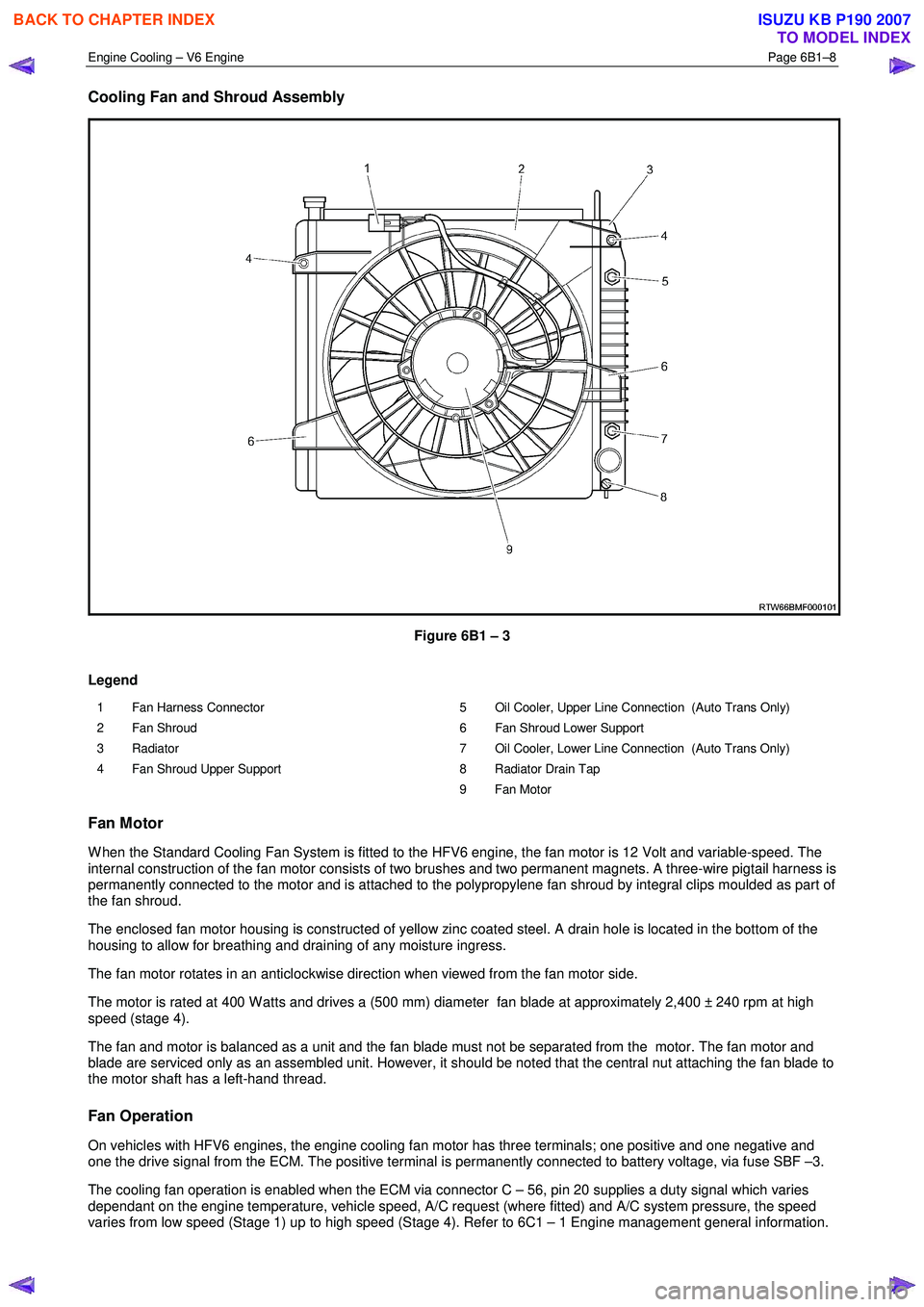
Cooling Fan and Shroud Assembly
Figure 6B1 – 3
Legend
1 Fan Harness Connector
2 Fan Shroud
3 Radiator
4 Fan Shroud Upper Support 5 Oil Cooler, Upper Line Connection (Auto Trans Only)
6 Fan Shroud Lower Support
7 Oil Cooler, Lower Line Connection (Auto Trans Only)
8 Radiator Drain Tap
9 Fan Motor
Fan Motor
W hen the Standard Cooling Fan System is fitted to the HFV6 engine, the fan motor is 12 Volt and variable-speed. The
internal construction of the fan motor consists of two brushes and two permanent magnets. A three-wire pigtail harness is
permanently connected to the motor and is attached to the polypropylene fan shroud by integral clips moulded as part of
the fan shroud.
The enclosed fan motor housing is constructed of yellow zinc coated steel. A drain hole is located in the bottom of the
housing to allow for breathing and draining of any moisture ingress.
The fan motor rotates in an anticlockwise direction when viewed from the fan motor side.
The motor is rated at 400 W atts and drives a (500 mm) diameter fan blade at approximately 2,400 ± 240 rpm at high
speed (stage 4).
The fan and motor is balanced as a unit and the fan blade must not be separated from the motor. The fan motor and
blade are serviced only as an assembled unit. However, it should be noted that the central nut attaching the fan blade to
the motor shaft has a left-hand thread.
Fan Operation
On vehicles with HFV6 engines, the engine cooling fan motor has three terminals; one positive and one negative and
one the drive signal from the ECM. The positive terminal is permanently connected to battery voltage, via fuse SBF –3.
The cooling fan operation is enabled when the ECM via connector C – 56, pin 20 supplies a duty signal which varies
dependant on the engine temperature, vehicle speed, A/C request (where fitted) and A/C system pressure, the speed
varies from low speed (Stage 1) up to high speed (Stage 4). Refer to 6C1 – 1 Engine management general information.
BACK TO CHAPTER INDEX
TO MODEL INDEX
ISUZU KB P190 2007
Page 3148 of 6020
Engine Cooling – V6 Engine Page 6B1–13
2.6 Coolant Filler Cap
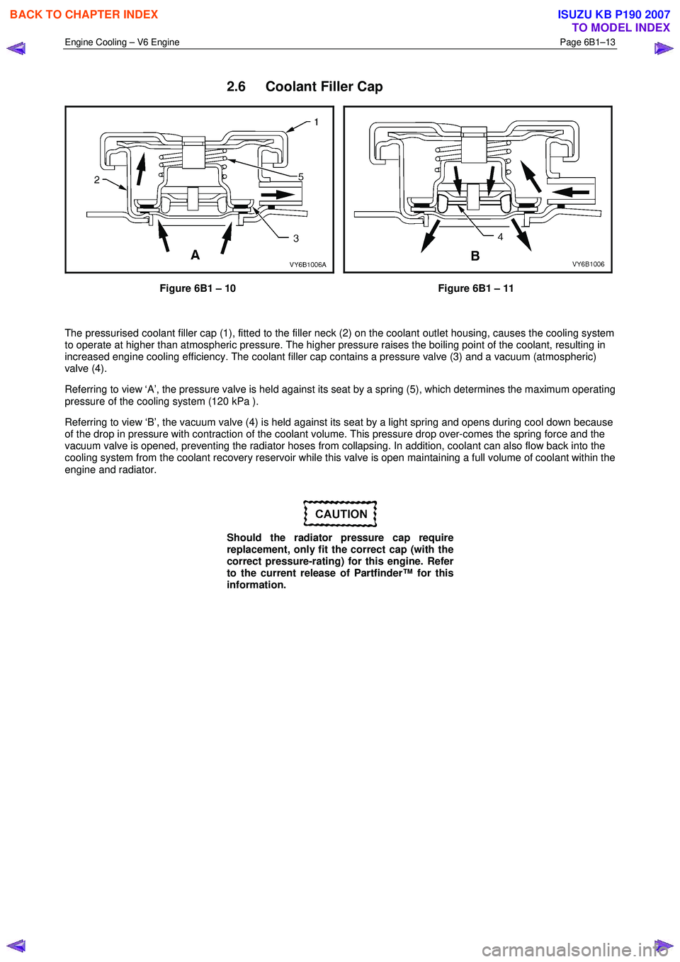
Figure 6B1 – 10 Figure 6B1 – 11
The pressurised coolant filler cap (1), fitted to the filler neck (2) on the coolant outlet housing, causes the cooling system
to operate at higher than atmospheric pressure. The higher pressure raises the boiling point of the coolant, resulting in
increased engine cooling efficiency. The coolant filler cap contains a pressure valve (3) and a vacuum (atmospheric)
valve (4).
Referring to view ‘A’, the pressure valve is held against its seat by a spring (5), which determines the maximum operating
pressure of the cooling system (120 kPa ).
Referring to view ‘B’, the vacuum valve (4) is held against its seat by a light spring and opens during cool down because
of the drop in pressure with contraction of the coolant volume. This pressure drop over-comes the spring force and the
vacuum valve is opened, preventing the radiator hoses from collapsing. In addition, coolant can also flow back into the
cooling system from the coolant recovery reservoir while this valve is open maintaining a full volume of coolant within the
engine and radiator.
Should the radiator pressure cap require
replacement, only fit the correct cap (with the
correct pressure-rating) for this engine. Refer
to the current release of Partfinder™ for this
information.
BACK TO CHAPTER INDEX
TO MODEL INDEX
ISUZU KB P190 2007
Page 3152 of 6020
Engine Cooling – V6 Engine Page 6B1–17
3 Top up as required, using a 50 / 50 mix of clean water and the recommended coolant, which is either DEX-COOL®
long-life coolant or its equivalent, known as Extended Life Anti-freeze Coolant conforming to GM specification
6277M. Refer to 3.2 Coolant Maintenance and 3.3 Draining and Filling Cooling System in this Section, for the
necessary procedures and further information.
3.2 Coolant Maintenance
Do not mix different types of anti-freeze or
corrosion inhibitors, as they may be
incompatible. If a different type has been used
in the cooling system, flush the system with
clean water, refer to 3.4 Cleaning Cooling
System – Cooling System Flush in this
Section and refill cooling system with the
correct coolant. Refer to 3.3 Draining and
Filling Cooling System in this Section.
The cooling system is designed to use a coolant (a mixture of ethylene glycol antifreeze with added corrosion inhibitors,
and water), rather than plain water. The use of glycol also raises the boiling point and increases the cooling system
efficiency. For this reason, it is of the utmost importance that the correct concentration level of ethylene glycol in the
cooling system is maintained.
Addition of plain water into the cooling system when 'topping-up' may dilute the coolant mixture to a point where the
antifreeze / anti-boil and corrosion inhibitor properties of ethylene glycol become ineffective.
The coolant should comprise of a mixture 50% ethylene glycol antifreeze / inhibitor with 50% clear, clean water.
Ethylene glycol conforming to the correct specification is either named DEX-COOL® long-life coolant or its equivalent,
known as Extended Life Anti-freeze Coolant conforming to GM specification 6277M. Both are available in a number of
different quantities. Check the current release of Partfinder™ for specific details.
BACK TO CHAPTER INDEX
TO MODEL INDEX
ISUZU KB P190 2007
Page 3158 of 6020

Engine Cooling – V6 Engine Page 6B1–23
1 W ith the engine off, remove the coolant filler cap on
the coolant outlet housing, located at the front left-
hand side of the engine.
Figure 6B1 – 19
2 If filling a completely empty cooling system for automatic transmission models, mix 5 litres of clean
water with 5 litres of the recommended coolant or
5.2 litres of each for manual transmission models.
3 Add coolant via the engine coolant filler neck on the coolant outlet housing.
NOTE
Do not replace the coolant filler cap before
starting the engine (in step 6). Leaving the filler
cap off allows the engine to warm up without
pressurising.
4 Reconnect battery ground lead. Refer to 6D1 – 3 Battery – V6.
5 Start the engine and set the HVAC controls to: • Full hot
• Low fan
Figure 6B1 – 20
6 Run the engine at approximately 2,000 rpm to warm up the engine.
7 W ait until the radiator fan switches on.
8 W hen the radiator fan has switched on, let the engine rpm drop back to idle.
9 Turn the engine off when the radiator fan switches off.
10 Top up the coolant until full.
11 Replace the coolant filler cap.
Do not loosen or remove the radiator filler cap
when the coolant temperature is high. Steam
or boiling coolant will gush out and you may
be burnt. To open the radiator filler cap, cover
the filler cap with a thick cloth when the
coolant has cooled, release the pressure by
slowly turning the filler cap, and remove the
cap.
BACK TO CHAPTER INDEX
TO MODEL INDEX
ISUZU KB P190 2007
Page 3168 of 6020
Engine Cooling – V6 Engine Page 6B1–33
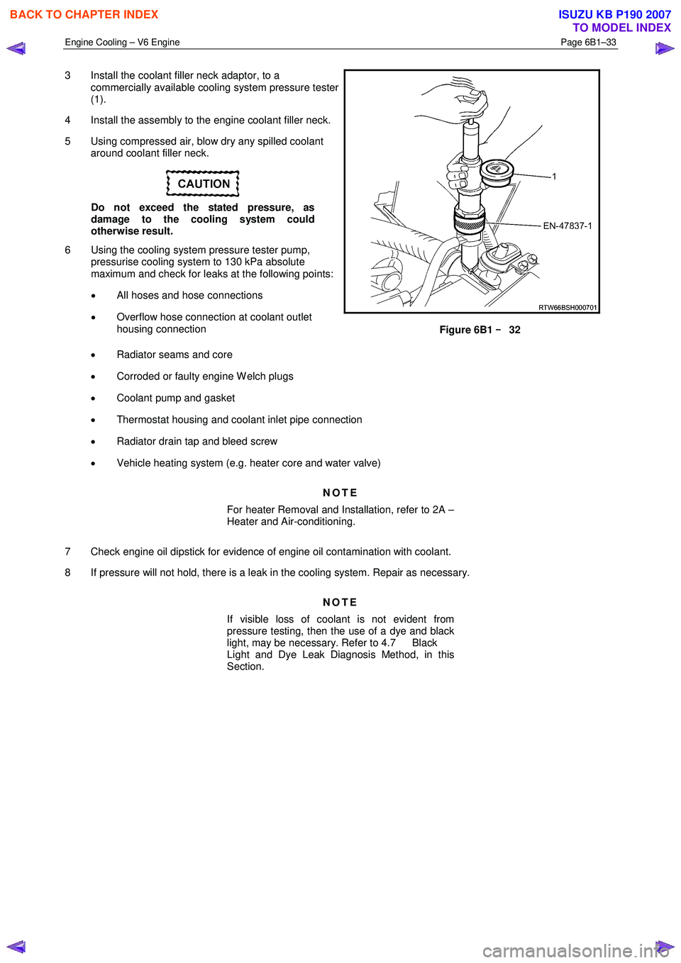
3 Install the coolant filler neck adaptor, to a
commercially available cooling system pressure tester
(1).
4 Install the assembly to the engine coolant filler neck.
5 Using compressed air, blow dry any spilled coolant around coolant filler neck.
Do not exceed the stated pressure, as
damage to the cooling system could
otherwise result.
6 Using the cooling system pressure tester pump, pressurise cooling system to 130 kPa absolute
maximum and check for leaks at the following points:
• All hoses and hose connections
• Overflow hose connection at coolant outlet
housing connection
Figure 6B1 –
––
–
32
• Radiator seams and core
• Corroded or faulty engine W elch plugs
• Coolant pump and gasket
• Thermostat housing and coolant inlet pipe connection
• Radiator drain tap and bleed screw
• Vehicle heating system (e.g. heater core and water valve)
NOTE
For heater Removal and Installation, refer to 2A –
Heater and Air-conditioning.
7 Check engine oil dipstick for evidence of engine oil contamination with coolant.
8 If pressure will not hold, there is a leak in the cooling system. Repair as necessary.
NOTE
If visible loss of coolant is not evident from
pressure testing, then the use of a dye and black
light, may be necessary. Refer to 4.7 Black
Light and Dye Leak Diagnosis Method, in this
Section.
BACK TO CHAPTER INDEX
TO MODEL INDEX
ISUZU KB P190 2007