Page 3078 of 6020
Engine Mechanical – V6 Page 6A1–301
Page 6A1–301
7 Install the M14 rear oil gallery threaded plug (1) and
tighten to the correct torque specification.
M14 cylinder block rear oil gallery
threaded plug torque specif ication .......... 27.0 – 35.0 Nm
Figure 6A1 – 546
8 Install the right-hand side M14 coolant drain threaded
plug (1) and tighten to the co rrect torque specification.
Right-hand side M14 cylinder block
coolant drain threaded plug
torque specificatio n ................................. 27. 0 – 35.0 Nm
Figure 6A1 – 547
9 Install the right-hand side M14 oil gallery threaded plug (1) and tighten to the co rrect torque specification.
Right-hand side M14 cylinder block
oil gallery threaded plug
torque specificatio n ................................. 27. 0 – 35.0 Nm
Figure 6A1 – 548
BACK TO CHAPTER INDEX
TO MODEL INDEX
ISUZU KB P190 2007
Page 3079 of 6020
Engine Mechanical – V6 Page 6A1–302
Page 6A1–302
10 Install the cylinder block-to-oil pan alignment
dowels (1).
Figure 6A1 – 549
11 Install the new right-hand front oil pan rail oil gallery expansion plug (1).
Figure 6A1 – 550
12 Install the oil jet (2), three places.
13 Install the oil jet attaching bolt (1), three places and tighten to the correct torque specification.
Oil jet attaching bolt
torque specificatio n ................................... 8. 0 – 12.0 Nm
Figure 6A1 – 551
BACK TO CHAPTER INDEX
TO MODEL INDEX
ISUZU KB P190 2007
Page 3084 of 6020
Engine Mechanical – V6 Page 6A1–307
Page 6A1–307
NOTE
All swarf must be removed from the tapped hole
prior to insert installation.
Safety glasses must be worn when using
compressed air.
9 Using compressed air, clean out any swarf.
Figure 6A1 – 563
NOTE
Do not allow oil or other foreign material to
contact the outside diameter (OD) of the insert.
10 Lubricate the threads of the driver installation tool (2)
with the driver oil (1).
Figure 6A1 – 564
11 Install the insert (2) onto t he driver installation tool (1).
Figure 6A1 – 565
BACK TO CHAPTER INDEX
TO MODEL INDEX
ISUZU KB P190 2007
Page 3086 of 6020

Engine Mechanical – V6 Page 6A1–309
Page 6A1–309
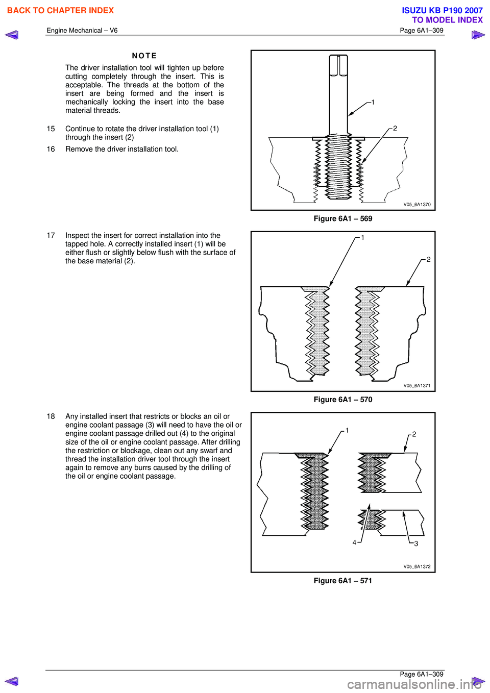
NOTE
The driver installation tool will tighten up before
cutting completely through the insert. This is
acceptable. The threads at the bottom of the
insert are being formed and the insert is
mechanically locking the insert into the base
material threads.
15 Continue to rotate the driver installation tool (1) through the insert (2)
16 Remove the driver installation tool.
Figure 6A1 – 569
17 Inspect the insert for co rrect installation into the
tapped hole. A correctly installed insert (1) will be
either flush or slightly below flush with the surface of
the base material (2).
Figure 6A1 – 570
18 Any installed insert that restricts or blocks an oil or
engine coolant passage (3) will need to have the oil or
engine coolant passage drilled out (4) to the original
size of the oil or engine c oolant passage. After drilling
the restriction or block age, clean out any swarf and
thread the installation driver tool through the insert
again to remove any burrs caused by the drilling of
the oil or engine coolant passage.
Figure 6A1 – 571
BACK TO CHAPTER INDEX
TO MODEL INDEX
ISUZU KB P190 2007
Page 3090 of 6020
Engine Mechanical – V6 Page 6A1–313
Page 6A1–313
11 Spray a commercially available thread cleaner into
the tapped hole.
Figure 6A1 – 580
NOTE
All swarf must be removed from the tapped hole
prior to insert installation.
Safety glasses must be worn when using
compressed air.
12 Using compressed air, clean out any swarf.
Figure 6A1 – 581
NOTE
• Do not remove the fixt ure plate, ensure the
fixture plate is in stalled during the
installation process of the insert.
• Do not allow oil or other foreign material to
contact the outside diam eter (OD) of the
insert.
13 Lubricate the threads of the driver installation tool (2)
with the driver oil (1).
Figure 6A1 – 582
BACK TO CHAPTER INDEX
TO MODEL INDEX
ISUZU KB P190 2007
Page 3096 of 6020
Engine Mechanical – V6 Page 6A1–319
Page 6A1–319
12 Spray a commercially available thread cleaner into
the tapped hole.
Figure 6A1 – 597
NOTE
All swarf must be removed from the tapped hole
prior to insert installation.
Safety glasses must be worn when using
compressed air.
13 Using compressed air, clean out any swarf.
Figure 6A1 – 598
NOTE
Do not allow oil or other foreign material to
contact the outside diameter (OD) of the insert.
14 Lubricate the threads of the driver installation tool (2)
with the driver oil (1).
Figure 6A1 – 599
BACK TO CHAPTER INDEX
TO MODEL INDEX
ISUZU KB P190 2007
Page 3121 of 6020
Engine Mechanical – V6 Page 6A1–344
Page 6A1–344
Oil Pan Front
Figure 6A1 – 626
Legend Hole Tool Number J 42385 Max. Depth in mm
Number Thread Size Drill Counter-
bore Tap Driver Insert Drill Tap
2 M8 x 1.25 206 207 208 209 210 28.5 23.0
3 M8 x 1.25 610 n/a 208 209 620 37.5 32.0
BACK TO CHAPTER INDEX
TO MODEL INDEX
ISUZU KB P190 2007
Page 3122 of 6020
Engine Mechanical – V6 Page 6A1–345
Page 6A1–345
Oil Pan Rear
Figure 6A1 – 627
Legend Hole Tool Number J 42385 Max. Depth in mm
Number Thread Size Drill Counter-
bore Tap Driver Insert Drill Tap
1 M10 x 1.5 211 212 213 214 215 Thru Thru
BACK TO CHAPTER INDEX
TO MODEL INDEX
ISUZU KB P190 2007