2007 ISUZU KB P190 ECO mode
[x] Cancel search: ECO modePage 2394 of 6020
6E–224 ENGINE DRIVEABILITY AND EMISSIONS
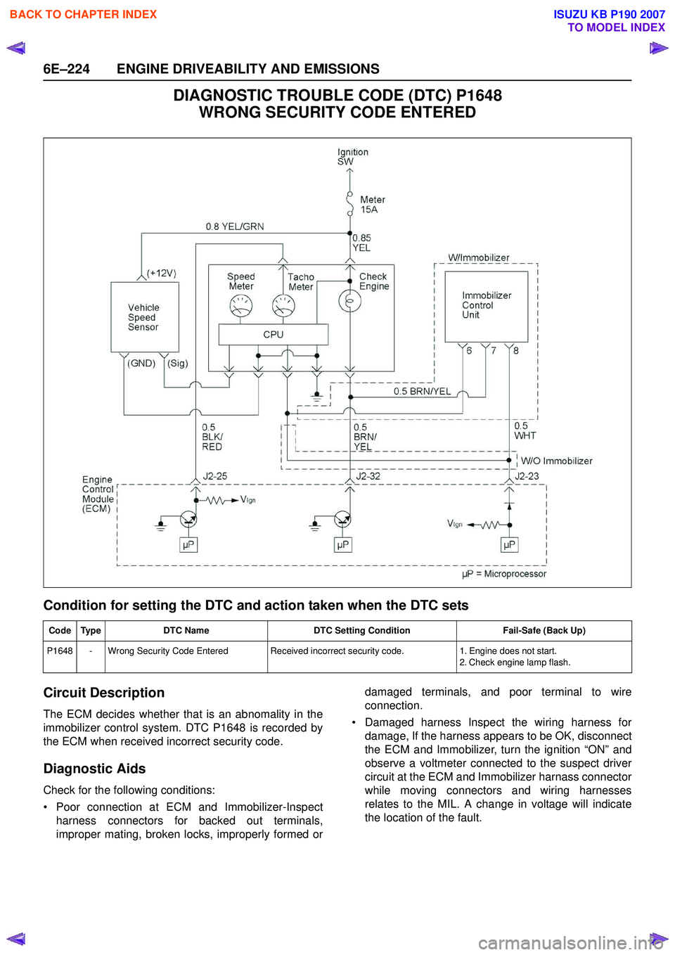
DIAGNOSTIC TROUBLE CODE (DTC) P1648 WRONG SECURITY CODE ENTERED
Condition for setting the DTC and action taken when the DTC sets
Circuit Description
The ECM decides whether that is an abnomality in the
immobilizer control system. DTC P1648 is recorded by
the ECM when received incorrect security code.
Diagnostic Aids
Check for the following conditions:
• Poor connection at ECM and Immobilizer-Inspect harness connectors for backed out terminals,
improper mating, broken locks, improperly formed or damaged terminals, and poor terminal to wire
connection.
• Damaged harness Inspect the wiring harness for damage, If the harness appears to be OK, disconnect
the ECM and Immobilizer, turn the ignition “ON” and
observe a voltmeter connected to the suspect driver
circuit at the ECM and Immobilizer harnass connector
while moving connectors and wiring harnesses
relates to the MIL. A change in voltage will indicate
the location of the fault.
Code Type DTC Name DTC Setting Condition Fail-Safe (Back Up)
P1648 - Wrong Security Code Entered Received incorrect security code. 1. Engine does not start.
2. Check engine lamp flash.
BACK TO CHAPTER INDEX
TO MODEL INDEX
ISUZU KB P190 2007
Page 2395 of 6020
ENGINE DRIVEABILITY AND EMISSIONS 6E–225
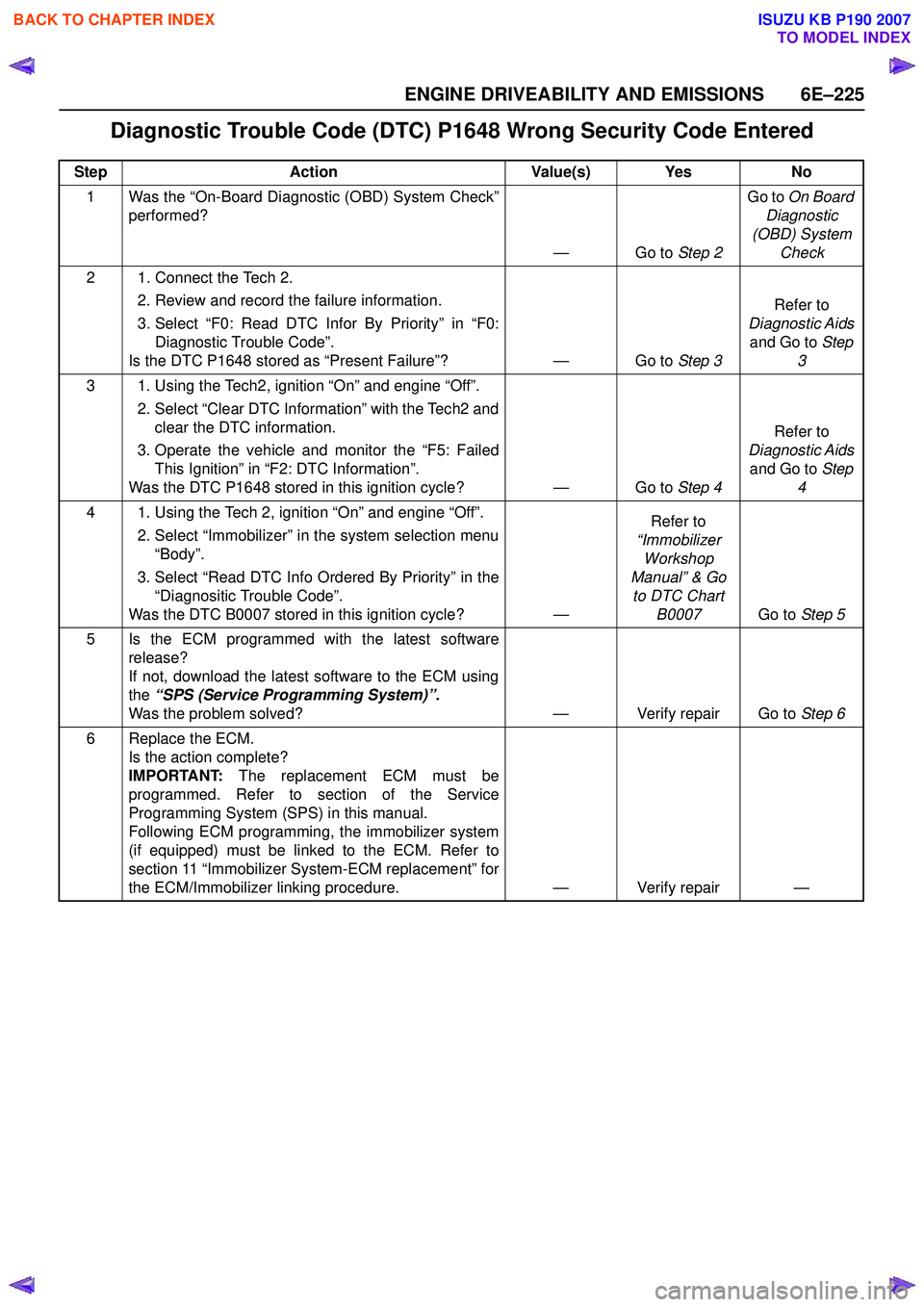
Diagnostic Trouble Code (DTC) P1648 Wrong Security Code Entered
StepAction Value(s) Yes No
1 Was the “On-Board Diagnostic (OBD) System Check” performed?
—Go to Step 2Go to
On Board
Diagnostic
(OBD) System Check
2 1. Connect the Tech 2. 2. Review and record the failure information.
3. Select “F0: Read DTC Infor By Priority” in “F0: Diagnostic Trouble Code”.
Is the DTC P1648 stored as “Present Failure”? — Go to Step 3Refer to
Diagnostic Aids and Go to Step
3
3 1. Using the Tech2, ignition “On” and engine “Off”. 2. Select “Clear DTC Information” with the Tech2 andclear the DTC information.
3. Operate the vehicle and monitor the “F5: Failed This Ignition” in “F2: DTC Information”.
Was the DTC P1648 stored in this ignition cycle? — Go to Step 4Refer to
Diagnostic Aids and Go to Step
4
4 1. Using the Tech 2, ignition “On” and engine “Off”. 2. Select “Immobilizer” in the system selection menu“Body”.
3. Select “Read DTC Info Ordered By Priority” in the “Diagnositic Trouble Code”.
Was the DTC B0007 stored in this ignition cycle? —Refer to
“Immobilizer Workshop
Manual” & Go to DTC Chart B0007 Go to Step 5
5 Is the ECM programmed with the latest software release?
If not, download the latest software to the ECM using
the “SPS (Service Programming System)”.
Was the problem solved? — Verify repair Go to Step 6
6 Replace the ECM. Is the action complete?
IMPORTANT: The replacement ECM must be
programmed. Refer to section of the Service
Programming System (SPS) in this manual.
Following ECM programming, the immobilizer system
(if equipped) must be linked to the ECM. Refer to
section 11 “Immobilizer System-ECM replacement” for
the ECM/Immobilizer linking procedure. — Verify repair —
BACK TO CHAPTER INDEX
TO MODEL INDEX
ISUZU KB P190 2007
Page 2396 of 6020

6E–226 ENGINE DRIVEABILITY AND EMISSIONS
DIAGNOSTIC TROUBLE CODE (DTC) P1649
IMMOBILIZER FUNCTION NOT PROGRAMMED
Condition for setting the DTC and action taken when the DTC sets
Circuit Description
The ECM decides whether that is an abnomality in the
immobilizer control system. DTC P1649 is recorded by
the ECM when security code & secret key not
programmed.
Diagnostic Aids
Check for the following conditions:
• Poor connection at ECM and Immobilizer-Inspect harness connectors for backed out terminals, improper mating, broken locks, improperly formed or
damaged terminals, and poor terminal to wire
connection.
• Damaged harness Inspect the wiring harness for damage, If the harness appears to be OK, disconnect
the ECM and Immobilizer, turn the ignition “ON” and
observe a voltmeter connected to the suspect driver
circuit at the ECM and Immobilizer harnass connector
while moving connectors and wiring harnesses
relates to the MIL. A change in voltage will indicate
the location of the fault.
Code Type DTC Name DTC Setting Condition Fail-Safe (Back Up)
P1649 - Immobilizer Function Not Programmed Immobilizer function is not programmed in the ECM.1. Engine does not start.
2. Check engine lamp flash.
BACK TO CHAPTER INDEX
TO MODEL INDEX
ISUZU KB P190 2007
Page 2397 of 6020
ENGINE DRIVEABILITY AND EMISSIONS 6E–227
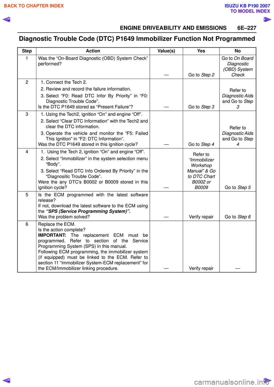
Diagnostic Trouble Code (DTC) P1649 Immobilizer Function Not Programmed
StepAction Value(s) Yes No
1 Was the “On-Board Diagnostic (OBD) System Check” performed?
—Go to Step 2Go to
On Board
Diagnostic
(OBD) System Check
2 1. Connect the Tech 2. 2. Review and record the failure information.
3. Select “F0: Read DTC Infor By Priority” in “F0: Diagnostic Trouble Code”.
Is the DTC P1649 stored as “Present Failure”? — Go to Step 3Refer to
Diagnostic Aids and Go to Step
3
3 1. Using the Tech2, ignition “On” and engine “Off”. 2. Select “Clear DTC Information” with the Tech2 andclear the DTC information.
3. Operate the vehicle and monitor the “F5: Failed This Ignition” in “F2: DTC Information”.
Was the DTC P1649 stored in this ignition cycle? — Go to Step 4Refer to
Diagnostic Aids and Go to Step
4
4 1. Using the Tech 2, ignition “On” and engine “Off”. 2. Select “Immobilizer” in the system selection menu“Body”.
3. Select “Read DTC Info Ordered By Priority” in the “Diagnositic Trouble Code”.
Were the any DTC's B0002 or B0009 stored in this
ignition cycle? —Refer to
“Immobilizer Workshop
Manual” & Go to DTC Chart B0002 or B0009 Go to Step 5
5 Is the ECM programmed with the latest software release?
If not, download the latest software to the ECM using
the “SPS (Service Programming System)”.
Was the problem solved? — Verify repair Go to Step 6
6 Replace the ECM. Is the action complete?
IMPORTANT: The replacement ECM must be
programmed. Refer to section of the Service
Programming System (SPS) in this manual.
Following ECM programming, the immobilizer system
(if equipped) must be linked to the ECM. Refer to
section 11 “Immobilizer System-ECM replacement” for
the ECM/Immobilizer linking procedure. — Verify repair —
BACK TO CHAPTER INDEX
TO MODEL INDEX
ISUZU KB P190 2007
Page 2399 of 6020
ENGINE DRIVEABILITY AND EMISSIONS 6E–229
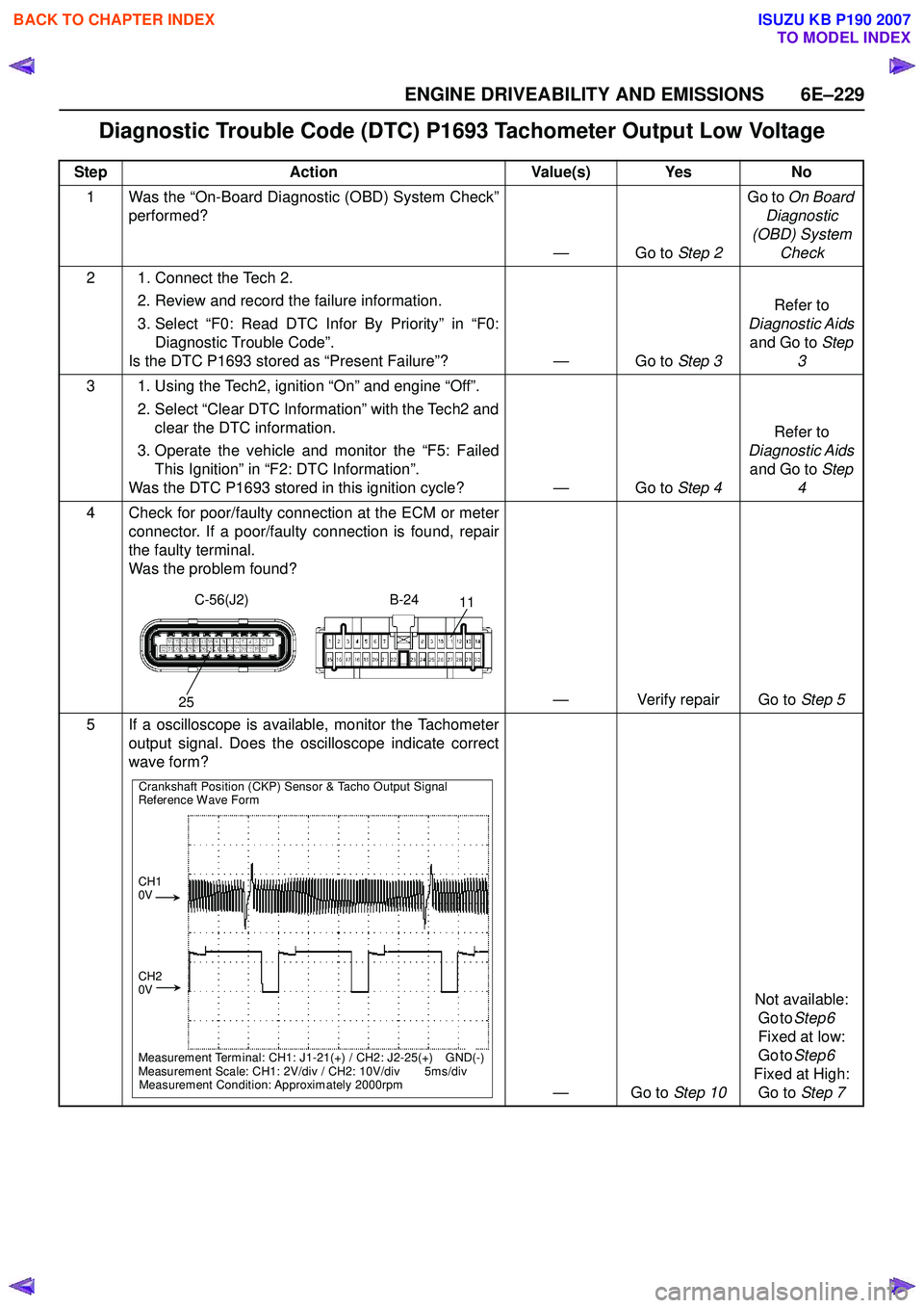
Diagnostic Trouble Code (DTC) P1693 Tachometer Output Low Voltage
StepAction Value(s) Yes No
1 Was the “On-Board Diagnostic (OBD) System Check” performed?
—Go to Step 2Go to
On Board
Diagnostic
(OBD) System Check
2 1. Connect the Tech 2. 2. Review and record the failure information.
3. Select “F0: Read DTC Infor By Priority” in “F0: Diagnostic Trouble Code”.
Is the DTC P1693 stored as “Present Failure”? — Go to Step 3Refer to
Diagnostic Aids and Go to Step
3
3 1. Using the Tech2, ignition “On” and engine “Off”. 2. Select “Clear DTC Information” with the Tech2 andclear the DTC information.
3. Operate the vehicle and monitor the “F5: Failed This Ignition” in “F2: DTC Information”.
Was the DTC P1693 stored in this ignition cycle? — Go to Step 4Refer to
Diagnostic Aids and Go to Step
4
4 Check for poor/faulty connection at the ECM or meter connector. If a poor/faulty connection is found, repair
the faulty terminal.
Was the problem found?
— Verify repair Go to Step 5
5 If a oscilloscope is available, monitor the Tachometer output signal. Does the oscilloscope indicate correct
wave form?
—Go to Step 10Not available:
Go to Step 6
Fixed at low: Go to Step 6
Fixed at High: Go to Step 7
25
C-56(J2) B-24
11
Crankshaft Position (CKP) Sensor & Tacho Output Signal
Reference Wave Form
CH1
0V
CH2
0V
Measurement Terminal: CH1: J1-21(+) / CH2: J2-25(+) GND(-)
Measurem ent Scale: CH1: 2V/div / CH2: 10V/div 5m s/div
Measurement Condition: Approxim ately 2000rpm
BACK TO CHAPTER INDEX
TO MODEL INDEX
ISUZU KB P190 2007
Page 2404 of 6020
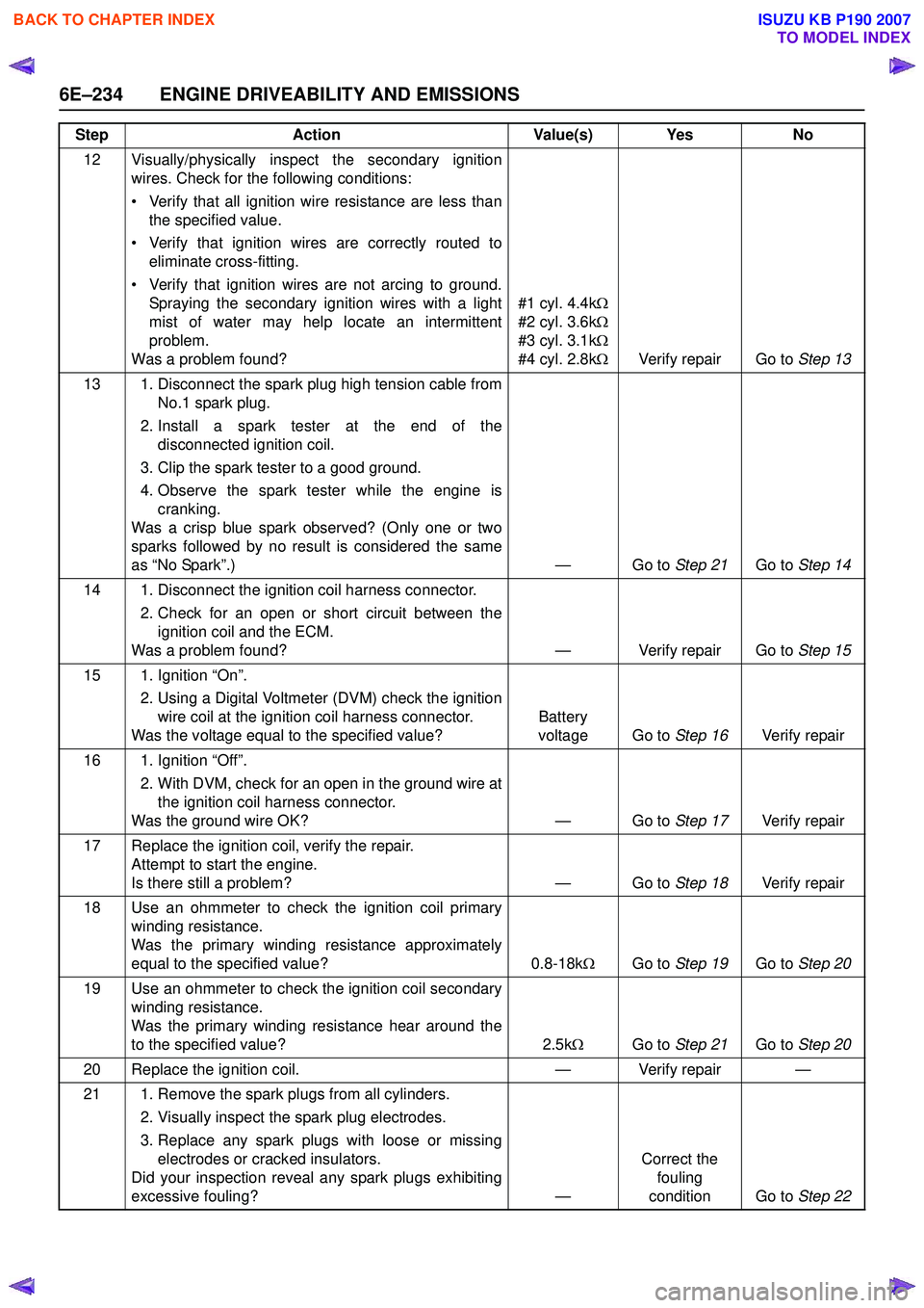
6E–234 ENGINE DRIVEABILITY AND EMISSIONS
12 Visually/physically inspect the secondary ignitionwires. Check for the following conditions:
• Verify that all ignition wire resistance are less than the specified value.
• Verify that ignition wires are correctly routed to eliminate cross-fitting.
• Verify that ignition wires are not arcing to ground. Spraying the secondary ignition wires with a light
mist of water may help locate an intermittent
problem.
Was a problem found? #1 cyl. 4.4k
Ω
#2 cyl. 3.6k Ω
#3 cyl. 3.1k Ω
#4 cyl. 2.8k ΩVerify repair Go to Step 13
13 1. Disconnect the spark plug high tension cable from No.1 spark plug.
2. Install a spark tester at the end of the disconnected ignition coil.
3. Clip the spark tester to a good ground.
4. Observe the spark tester while the engine is cranking.
Was a crisp blue spark observed? (Only one or two
sparks followed by no result is considered the same
as “No Spark”.) — Go to Step 21Go to Step 14
14 1. Disconnect the ignition coil harness connector. 2. Check for an open or short circuit between theignition coil and the ECM.
Was a problem found? — Verify repair Go to Step 15
15 1. Ignition “On”. 2. Using a Digital Voltmeter (DVM) check the ignitionwire coil at the ignition coil harness connector.
Was the voltage equal to the specified value? Battery
voltage Go to Step 16Verify repair
16 1. Ignition “Off”. 2. With DVM, check for an open in the ground wire atthe ignition coil harness connector.
Was the ground wire OK? — Go to Step 17Verify repair
17 Replace the ignition coil, verify the repair. Attempt to start the engine.
Is there still a problem? — Go to Step 18Verify repair
18 Use an ohmmeter to check the ignition coil primary winding resistance.
Was the primary winding resistance approximately
equal to the specified value? 0.8-18kΩGo to Step 19 Go to Step 20
19 Use an ohmmeter to check the ignition coil secondary winding resistance.
Was the primary winding resistance hear around the
to the specified value? 2.5kΩ Go to Step 21 Go to Step 20
20 Replace the ignition coil. — Verify repair —
21 1. Remove the spark plugs from all cylinders. 2. Visually inspect the spark plug electrodes.
3. Replace any spark plugs with loose or missing electrodes or cracked insulators.
Did your inspection reveal any spark plugs exhibiting
excessive fouling? —Correct the
fouling
condition Go to Step 22
Step
Action Value(s) Yes No
BACK TO CHAPTER INDEX
TO MODEL INDEX
ISUZU KB P190 2007
Page 2407 of 6020
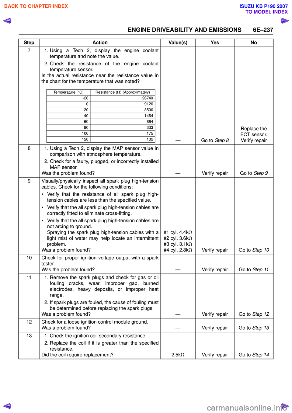
ENGINE DRIVEABILITY AND EMISSIONS 6E–237
7 1. Using a Tech 2, display the engine coolanttemperature and note the value.
2. Check the resistance of the engine coolant temperature sensor.
Is the actual resistance near the resistance value in
the chart for the temperature that was noted?
—Go to Step 8Replace the
ECT sensor. Verify repair
8 1. Using a Tech 2, display the MAP sensor value in comparison with atmosphere temperature.
2. Check for a faulty, plugged, or incorrectly installed MAP sensor.
Was the problem found? — Verify repair Go to Step 9
9 Visually/physically inspect all spark plug high-tension cables. Check for the following conditions:
• Verify that the resistance of all spark plug high- tension cables are less than the specified value.
• Verify that the all spark plug high-tension cables are correctly fitted to eliminate cross-fitting.
• Verify that the all spark plug high-tension cables are not arcing to ground.
Spraying the spark plug high-tension cables with a
light mist of water may help locate an intermittent
problem.
Was a problem found? #1 cyl. 4.4k
Ω
#2 cyl. 3.6k Ω
#3 cyl. 3.1k Ω
#4 cyl. 2.8k ΩVerify repair Go to Step 10
10 Check for proper ignition voltage output with a spark tester.
Was the problem found? — Verify repair Go to Step 11
11 1. Remove the spark plugs and check for gas or oil fouling cracks, wear, improper gap, burned
electrodes, heavy deposits, or improper heat
range.
2. If spark plugs are fouled, the cause of fouling must be determined before replacing the spark plugs.
Was a problem found? — Verify repair Go to Step 12
12 Check for a loose ignition control module ground. Was a problem found? — Verify repair Go to Step 13
13 1. Check the ignition coil secondary resistance. 2. Replace the coil if it is greater than the specifiedresistance.
Did the coil require replacement? 2.5kΩ Verify repair Go to Step 14
Step
Action Value(s) Yes No
Temperature (°C) Resistance (Ω) (Approximately)
-20 26740
0 9120
20 3500
40 1464
60 664
80 333
100 175
120 102
BACK TO CHAPTER INDEX
TO MODEL INDEX
ISUZU KB P190 2007
Page 2413 of 6020
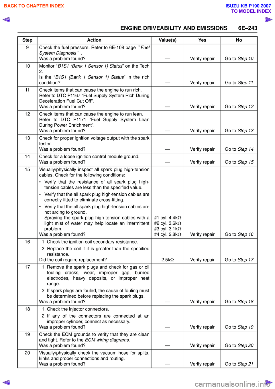
ENGINE DRIVEABILITY AND EMISSIONS 6E–243
9 Check the fuel pressure. Refer to 6E-108 page“Fuel
System Diagnosis
”.
Was a problem found? — Verify repair Go to Step 10
10 Monitor “ B1S1 (Bank 1 Sensor 1) Status ” on the Tech
2.
Is the “ B1S1 (Bank 1 Sensor 1) Status ” in the rich
condition? — Verify repair Go to Step 11
11 Check items that can cause the engine to run rich. Refer to DTC P1167 “Fuel Supply System Rich During
Deceleration Fuel Cut Off”.
Was a problem found? — Verify repair Go to Step 12
12 Check items that can cause the engine to run lean. Refer to DTC P1171 “Fuel Supply System Lean
During Power Enrichment”.
Was a problem found? — Verify repair Go to Step 13
13 Check for proper ignition voltage output with the spark tester.
Was a problem found? — Verify repair Go to Step 14
14 Check for a loose ignition control module ground. Was a problem found? — Verify repair Go to Step 15
15 Visually/physically inspect all spark plug high-tension cables. Check for the following conditions:
• Verify that the resistance of all spark plug high- tension cables are less than the specified value.
• Verify that the all spark plug high-tension cables are correctly fitted to eliminate cross-fitting.
• Verify that the all spark plug high-tension cables are not arcing to ground.
Spraying the spark plug high-tension cables with a
light mist of water may help locate an intermittent
problem.
Was a problem found? #1 cyl. 4.4k
Ω
#2 cyl. 3.6k Ω
#3 cyl. 3.1k Ω
#4 cyl. 2.8k ΩVerify repair Go to Step 16
16 1. Check the ignition coil secondary resistance. 2. Replace the coil if it is greater than the specifiedresistance.
Did the coil require replacement? 2.5kΩ Verify repair Go to Step 17
17 1. Remove the spark plugs and check for gas or oil fouling cracks, wear, improper gap, burned
electrodes, heavy deposits, or improper heat
range.
2. If spark plugs are fouled, the cause of fouling must be determined before replacing the spark plugs.
Was a problem found? — Verify repair Go to Step 18
18 1. Check the injector connectors. 2. If any of the connectors are connected at animproper cylinder, connect as necessary.
Was a problem found? — Verify repair Go to Step 19
19 Check the ECM grounds to verify that they are clean and tight. Refer to the ECM wiring diagrams.
Was a problem found? — Verify repair Go to Step 20
20 Visually/physically check the vacuum hose for splits, kinks and proper connections and routing.
Was a problem found? — Verify repair Go to Step 21
Step
Action Value(s) Yes No
BACK TO CHAPTER INDEX
TO MODEL INDEX
ISUZU KB P190 2007