2007 ISUZU KB P190 ECO mode
[x] Cancel search: ECO modePage 2416 of 6020
6E–246 ENGINE DRIVEABILITY AND EMISSIONS
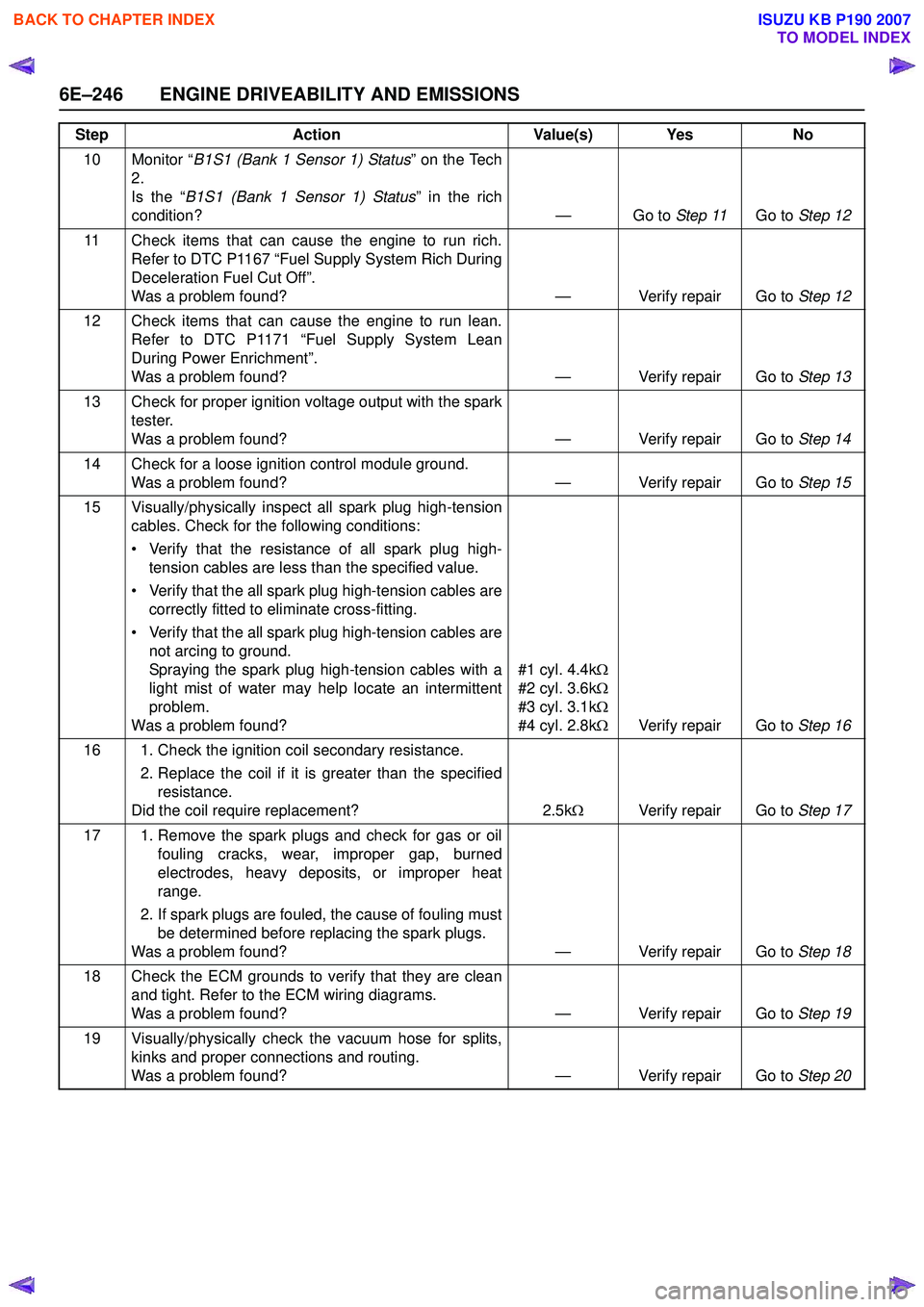
10 Monitor “B1S1 (Bank 1 Sensor 1) Status ” on the Tech
2.
Is the “ B1S1 (Bank 1 Sensor 1) Status ” in the rich
condition? — Go to Step 11Go to Step 12
11 Check items that can cause the engine to run rich. Refer to DTC P1167 “Fuel Supply System Rich During
Deceleration Fuel Cut Off”.
Was a problem found? — Verify repair Go to Step 12
12 Check items that can cause the engine to run lean. Refer to DTC P1171 “Fuel Supply System Lean
During Power Enrichment”.
Was a problem found? — Verify repair Go to Step 13
13 Check for proper ignition voltage output with the spark tester.
Was a problem found? — Verify repair Go to Step 14
14 Check for a loose ignition control module ground. Was a problem found? — Verify repair Go to Step 15
15 Visually/physically inspect all spark plug high-tension cables. Check for the following conditions:
• Verify that the resistance of all spark plug high- tension cables are less than the specified value.
• Verify that the all spark plug high-tension cables are correctly fitted to eliminate cross-fitting.
• Verify that the all spark plug high-tension cables are not arcing to ground.
Spraying the spark plug high-tension cables with a
light mist of water may help locate an intermittent
problem.
Was a problem found? #1 cyl. 4.4k
Ω
#2 cyl. 3.6k Ω
#3 cyl. 3.1k Ω
#4 cyl. 2.8k ΩVerify repair Go to Step 16
16 1. Check the ignition coil secondary resistance. 2. Replace the coil if it is greater than the specifiedresistance.
Did the coil require replacement? 2.5kΩ Verify repair Go to Step 17
17 1. Remove the spark plugs and check for gas or oil fouling cracks, wear, improper gap, burned
electrodes, heavy deposits, or improper heat
range.
2. If spark plugs are fouled, the cause of fouling must be determined before replacing the spark plugs.
Was a problem found? — Verify repair Go to Step 18
18 Check the ECM grounds to verify that they are clean and tight. Refer to the ECM wiring diagrams.
Was a problem found? — Verify repair Go to Step 19
19 Visually/physically check the vacuum hose for splits, kinks and proper connections and routing.
Was a problem found? — Verify repair Go to Step 20
Step
Action Value(s) Yes No
BACK TO CHAPTER INDEX
TO MODEL INDEX
ISUZU KB P190 2007
Page 2426 of 6020
6E–256 ENGINE DRIVEABILITY AND EMISSIONS
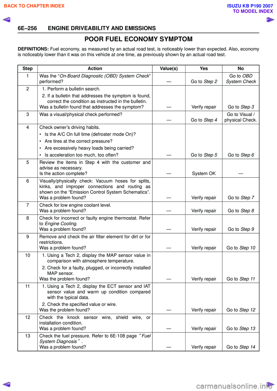
POOR FUEL ECONOMY SYMPTOM
DEFINITIONS: Fuel economy, as measured by an actual road test, is noticeably lower than expected. Also, economy
is noticeably lower than it was on this vehicle at one time, as previously shown by an actual road test.
Step Action Value(s) Yes No
1 Was the “ On-Board Diagnostic (OBD) System Check ”
performed? — Go to Step 2Go to
OBD
System Check
2 1. Perform a bulletin search. 2. If a bulletin that addresses the symptom is found,correct the condition as instructed in the bulletin.
Was a bulletin found that addresses the symptom? — Verify repair Go to Step 3
3 Was a visual/physical check performed? —Go to Step 4Go to Visual /
physical Check.
4 Check owner’s driving habits. • Is the A/C On full time (defroster mode On)?
• Are tires at the correct pressure?
• Are excessively heavy loads being carried?
• Is acceleration too much, too often? — Go to Step 5Go to Step 6
5 Review the items in Step 4 with the customer and advise as necessary.
Is the action complete? — System OK —
6 Visually/physically check: Vacuum hoses for splits, kinks, and improper connections and routing as
shown on the “Emission Control System Schematics”.
Was a problem found? — Verify repair Go to Step 7
7 Check for low engine coolant level. Was a problem found? — Verify repair Go to Step 8
8 Check for incorrect or faulty engine thermostat. Refer to Engine Cooling .
Was a problem found? — Verify repair Go to Step 9
9 Remove and check the air filter element for dirt or for restrictions.
Was a problem found? — Verify repair Go to Step 10
10 1. Using a Tech 2, display the MAP sensor value in comparison with atmosphere temperature.
2. Check for a faulty, plugged, or incorrectly installed MAP sensor.
Was the problem found? — Verify repair Go to Step 11
11 1. Using a Tech 2, display the ECT sensor and IAT sensor value and warm up condition compared
with the typical data.
2. Check the specified value or wire.
Was the problem found? — Verify repair Go to Step 12
12 Check the knock sensor wire, shield wire, or installation condition.
Was a problem found? — Verify repair Go to Step 13
13 Check the fuel pressure. Refer to 6E-108 page “Fuel
System Diagnosis
” .
Was a problem found? — Verify repair Go to Step 14
BACK TO CHAPTER INDEX
TO MODEL INDEX
ISUZU KB P190 2007
Page 2440 of 6020
6E–270 ENGINE DRIVEABILITY AND EMISSIONS
FUEL PRESSURE RELIEF
Caution: To reduce the risk of fire and personal
injury, it is necessary to relieve the fuel system
pressure before servicing the fuel system
components.
Caution: After relieving the fuel system pressure, a
small amount of fuel may be released when
servicing fuel lines or connections. Reduce the
chance of personal injury by covering the fuel line
fitting with a short towel before disconnecting the
fittings. The towel will absorb any fuel that may leak
out. When the disconnect is completed, place the
towel in an approved container.
1. Remove the fuel filler cap.
2. Remove the fuel pump relay from the underhood relay box.
3. Start the engine and allow it to stall.
4. Crank the engine for about 30 seconds.
5. Disconnect the negative battery cable.
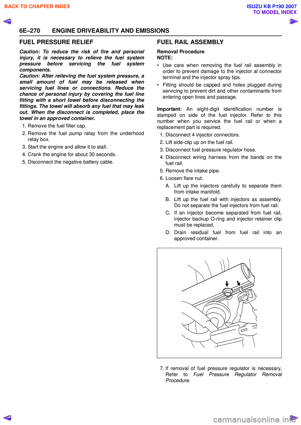
FUEL RAIL ASSEMBLY
Removal Procedure
NOTE:
• Use care when removing the fuel rail assembly in order to prevent damage to the injector al connector
terminal and the injector spray tips.
• Fitting should be capped and holes plugged during servicing to prevent dirt and other contaminants from
entering open lines and passage.
Important: An eight-digit identification number is
stamped on side of the fuel injector. Refer to this
number when you service the fuel rail or when a
replacement part is required.
1. Disconnect 4 injector connectors.
2. Lift side-clip up on the fuel rail.
3. Disconnect fuel pressure regulator hose.
4. Disconnect wiring harness from the bands on the fuel rail.
5. Remove the intake pipe.
6. Loosen flare nut.
A. Lift up the injectors carefully to separate them from intake manifold.
B. Lift up the fuel rail with injectors as assembly. Do not separate the fuel injectors from fuel rail.
C. If an injector become separated from fuel rail, injector backup O-ring and injector retainer clip
must be replaced.
D. Drain residual fuel from fuel rail into an approved container.
7. If removal of fuel pressure regulator is necessary, Refer to Fuel Pressure Regulator Removal
Procedure .
BACK TO CHAPTER INDEX
TO MODEL INDEX
ISUZU KB P190 2007
Page 2447 of 6020
ENGINE DRIVEABILITY AND EMISSIONS 6E–277
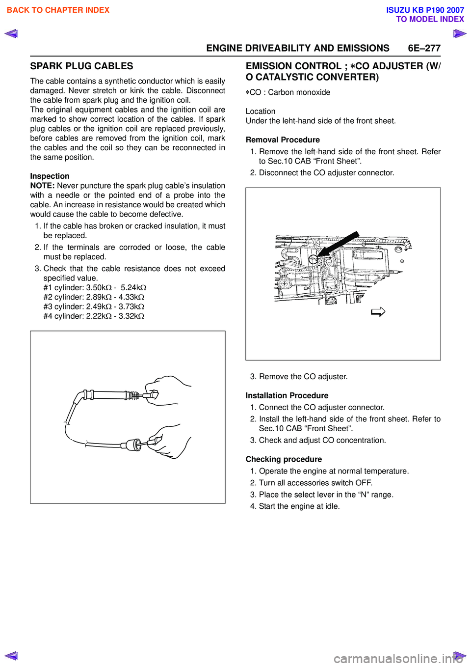
SPARK PLUG CABLES
The cable contains a synthetic conductor which is easily
damaged. Never stretch or kink the cable. Disconnect
the cable from spark plug and the ignition coil.
The original equipment cables and the ignition coil are
marked to show correct location of the cables. If spark
plug cables or the ignition coil are replaced previously,
before cables are removed from the ignition coil, mark
the cables and the coil so they can be reconnected in
the same position.
Inspection
NOTE: Never puncture the spark plug cable’s insulation
with a needle or the pointed end of a probe into the
cable. An increase in resistance would be created which
would cause the cable to become defective.
1. If the cable has broken or cracked insulation, it must be replaced.
2. If the terminals are corroded or loose, the cable must be replaced.
3. Check that the cable resistance does not exceed specified value.
#1 cylinder: 3.50k Ω - 5.24k Ω
#2 cylinder: 2.89k Ω - 4.33k Ω
#3 cylinder: 2.49k Ω - 3.73k Ω
#4 cylinder: 2.22k Ω - 3.32k Ω
EMISSION CONTROL ; *
**
*
CO ADJUSTER (W/
O CATALYSTIC CONVERTER)
* CO : Carbon monoxide
Location
Under the leht-hand side of the front sheet.
Removal Procedure 1. Remove the left-hand side of the front sheet. Refer to Sec.10 CAB “Front Sheet”.
2. Disconnect the CO adjuster connector.
3. Remove the CO adjuster.
Installation Procedure 1. Connect the CO adjuster connector.
2. Install the left-hand side of the front sheet. Refer to Sec.10 CAB “Front Sheet”.
3. Check and adjust CO concentration.
Checking procedure 1. Operate the engine at normal temperature.
2. Turn all accessories switch OFF.
3. Place the select lever in the “N” range.
4. Start the engine at idle.
BACK TO CHAPTER INDEX
TO MODEL INDEX
ISUZU KB P190 2007
Page 2481 of 6020
Engine Mechanical – V6 Page 6A1–2
Visual / Physical Inspection ................................................................................................................................ 28
Intermittent ........................................................................................................................................................... 28
2.3 Engine Misfire without Internal Engine Noises .................................................................................. ............... 29
2.4 Engine Misfire with Abnormal Internal Lower Engine Noises...................................................................... .... 30
2.5 Engine Misfire with Abnormal Valve Train Noise .............................................................................................. 31
2.6 Engine Misfire with Coolant Consumption ........................................................................................................ 31
2.7 Engine Misfire with Excessive Oil Consumption .................................................................................. ............ 31
2.8 Engine Noise on Start-up, but only Lasting a Few Seconds ....................................................................... ..... 31
2.9 Upper Engine Noise, Regardless of Engine Speed........................................................................................... 33
2.10 Lower Engine Noise, Regardless of Engine Speed ................................................................................. ......... 34
2.11 Engine Noise Under Load ................................................................................................................................... 35
2.12 Engine Will Not Crank – Crankshaft Will Not Rotate ............................................................................. ........... 35
2.13 Coolant in Combustion Chamber ....................................................................................................................... 37
Definition .............................................................................................................................................................. 37
2.14 Coolant in Engine Oil.......................................................................................................... ................................. 37
Definition .............................................................................................................................................................. 37
2.15 Engine Compression Test ........................................................................................................ ........................... 38
Preliminary Steps................................................................................................................................................. 38
Engine Cylinder Compression Test ............................................................................................... .................... 38
Test Result Evaluation......................................................................................................................................... 38
2.16 Cylinder Leakage Test .......................................................................................................... ............................... 39
2.17 Engine Oil Consumption Diagnosis ............................................................................................... .................... 39
Definition .............................................................................................................................................................. 39
2.18 Engine Oil Leak Diagnosis ...................................................................................................... ............................ 40
Introduction .......................................................................................................................................................... 40
Locating and Identifying the Leak .............................................................................................. ........................ 40
Visual Inspection ................................................................................................................................................. 40
Powder Method .................................................................................................................. .................................. 40
Black Light and Dye Method ..................................................................................................... .......................... 40
Possible Causes for Engine Oil Leaks ........................................................................................... .................... 41
2.19 Engine Oil Pressure Diagnosis ........................................................................................................................... 42
2.20 Accessory Drive Belt Diagnosis ................................................................................................. ........................ 42
Tension Check ..................................................................................................................................................... 42
Inspect .................................................................................................................................................................. 42
Drive Belt Chirp .................................................................................................................................................... 43
Definition .......................................................................................................................................................... 43
Diagnostic Aids................................................................................................................................................. 43
Test Description ............................................................................................................... ................................ 43
Diagnostic Table............................................................................................................................................... 44
Drive Belt Squeal .............................................................................................................. ................................... 45
Definition .......................................................................................................................................................... 45
Diagnostic Aids................................................................................................................................................. 45
Test Description ............................................................................................................... ................................ 45
Diagnostic Table............................................................................................................................................... 46
Drive Belt Whine ............................................................................................................... ................................... 46
Definition .......................................................................................................................................................... 46
Diagnostic Aids................................................................................................................................................. 46
Test Description ............................................................................................................... ................................ 46
Diagnostic Table............................................................................................................................................... 47
Drive Belt Rumble .............................................................................................................. .................................. 47
Definition .......................................................................................................................................................... 47
Diagnostic Aids................................................................................................................................................. 48
Test Description ............................................................................................................... ................................ 48
Diagnostic Table............................................................................................................................................... 48
Drive Belt Vibration........................................................................................................... ................................... 49
Definition .......................................................................................................................................................... 49
Diagnostic Aids................................................................................................................................................. 49
Test Description ............................................................................................................... ................................ 49
Diagnostic Table............................................................................................................................................... 50
Drive Belt Falls Off ........................................................................................................... .................................... 50
BACK TO CHAPTER INDEX
TO MODEL INDEX
ISUZU KB P190 2007
Page 2483 of 6020
Engine Mechanical – V6 Page 6A1–4
Reinstall ................................................................................................................................................................ 81
3.13 Crankshaft Balancer Assembly ................................................................................................... ....................... 84
Remove ................................................................................................................................................................. 84
Clean and Inspect .............................................................................................................. .................................. 85
Reinstall ................................................................................................................................................................ 85
3.14 Crankshaft Front Seal.......................................................................................................... ................................ 87
Replace ................................................................................................................................................................. 87
3.15 Front Cover Assembly........................................................................................................... .............................. 87
Remove ................................................................................................................................................................. 87
Disassemble ......................................................................................................................................................... 89
Clean ..................................................................................................................................................................... 90
Inspect .................................................................................................................................................................. 91
Reassemble .......................................................................................................................................................... 91
Reinstall ...................................................................................................................... .......................................... 92
3.16 Timing Chains, Tensioners, Shoes and Guides .................................................................................... ............ 94
Primary and Left-hand Secondary Timing Chain Installation ...................................................................... .... 94
Right-hand Secondary Timing Chain Installation ............................................................................................. 95
Remove ................................................................................................................................................................. 96
Right-hand Secondary Timing Chain.............................................................................................. .................. 96
Primary Timing Chain ..................................................................................................................................... 100
Left-hand Secondary Timing Chain ............................................................................................... ................. 102
Clean ................................................................................................................................................................... 105
Inspect ................................................................................................................................................................ 106
Timing Chains .................................................................................................................. .............................. 106
Camshaft Intermediate Driveshaft Sprockets ..................................................................................... ............ 106
Inlet and Exhaust Camshaft Sprocket ............................................................................................................ 106
Crankshaft Sprocket ....................................................................................................................................... 107
Primary Timing Chain Upper Guide............................................................................................... ................. 107
Primary Timing Chain Lower Guide................................................................................................................ 107
Primary Timing Chain Tensioner .................................................................................................................... 108
Left-hand Secondary Timing Chain Guide ......................................................................................... ............ 108
Left-hand Secondary Timing Chain Shoe....................................................................................................... 109
Left-hand Secondary Timing Chain Tensioner ..................................................................................... .......... 109
Right-hand Secondary Timing Chain Guide ................................................................................................... 110
Right-hand Secondary Timing Chain Shoe .................................................................................................... 110
Right-hand Secondary Timing Chain Tensioner.................................................................................... ......... 111
Reinstall .............................................................................................................................................................. 111
Left-hand Secondary Timing Chain Components.................................................................................... ....... 111
Primary Timing chain Components ................................................................................................................ 121
Right-hand Secondary Timing Chain Components ................................................................................... ..... 128
3.17 Oil Pump Assembly ........................................................................................................................................... 136
Remove ............................................................................................................................................................... 136
Disassemble ....................................................................................................................................................... 137
Clean ................................................................................................................................................................... 138
Inspect ................................................................................................................................................................ 139
Reassemble ........................................................................................................................................................ 141
Reinstall ...................................................................................................................... ........................................ 141
3.18 Camshaft Sprocket .............................................................................................................. .............................. 141
Remove ............................................................................................................................................................... 141
Right-hand Side................................................................................................................ .............................. 141
Left-hand Side ................................................................................................................................................ 144
Clean ................................................................................................................................................................... 146
Inspect ................................................................................................................................................................ 146
Reinstall ...................................................................................................................... ........................................ 147
3.19 Camshaft....................................................................................................................... ...................................... 147
Remove ............................................................................................................................................................... 147
Right-hand Side................................................................................................................ .............................. 147
Left-hand Side ................................................................................................................................................ 149
Clean ................................................................................................................................................................... 150
Inspect ................................................................................................................................................................ 150
BACK TO CHAPTER INDEX
TO MODEL INDEX
ISUZU KB P190 2007
Page 2487 of 6020
Engine Mechanical – V6 Page 6A1–8
1 General Information
The HFV6 engine features a closed vee, deep skirt die cast aluminium cylinder block with cast iron cylinder liners,
internally balanced crankcase, full length water jackets and six bolt main bearing caps.
The cylinders are arranged in two banks of three with a 60 degree included angle between the two banks.
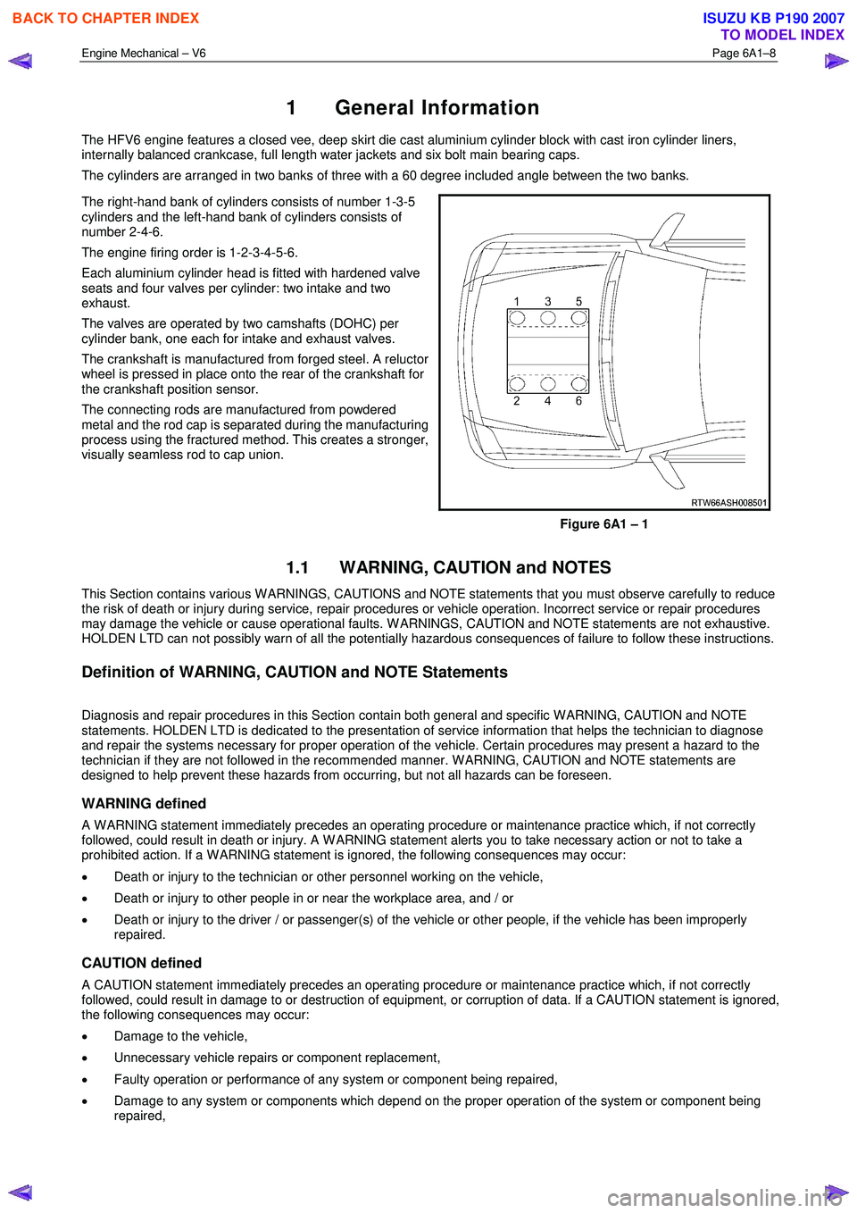
The right-hand bank of cylinders consists of number 1-3-5
cylinders and the left-hand bank of cylinders consists of
number 2-4-6.
The engine firing order is 1-2-3-4-5-6.
Each aluminium cylinder head is fitted with hardened valve
seats and four valves per cylinder: two intake and two
exhaust.
The valves are operated by two camshafts (DOHC) per
cylinder bank, one each for intake and exhaust valves.
The crankshaft is manufactured from forged steel. A reluctor
wheel is pressed in place onto the rear of the crankshaft for
the crankshaft position sensor.
The connecting rods are manufactured from powdered
metal and the rod cap is separated during the manufacturing
process using the fractured method. This creates a stronger,
visually seamless rod to cap union.
Figure 6A1 – 1
1.1 WARNING, CAUTION and NOTES
This Section contains various W ARNINGS, CAUTIONS and NOTE statements that you must observe carefully to reduce
the risk of death or injury during service, repair procedures or vehicle operation. Incorrect service or repair procedures
may damage the vehicle or cause operational faults. W ARNINGS, CAUTION and NOTE statements are not exhaustive.
HOLDEN LTD can not possibly warn of all the potentially hazardous consequences of failure to follow these instructions.
Definition of WARNING, CAUTION and NOTE Statements
Diagnosis and repair procedures in this Section contain both general and specific W ARNING, CAUTION and NOTE
statements. HOLDEN LTD is dedicated to the presentation of service information that helps the technician to diagnose
and repair the systems necessary for proper operation of the vehicle. Certain procedures may present a hazard to the
technician if they are not followed in the recommended manner. W ARNING, CAUTION and NOTE statements are
designed to help prevent these hazards from occurring, but not all hazards can be foreseen.
WARNING defined
A W ARNING statement immediately precedes an operating procedure or maintenance practice which, if not correctly
followed, could result in death or injury. A W ARNING statement alerts you to take necessary action or not to take a
prohibited action. If a W ARNING statement is ignored, the following consequences may occur:
• Death or injury to the technician or other personnel working on the vehicle,
• Death or injury to other people in or near the workplace area, and / or
• Death or injury to the driver / or passenger(s) of the vehicle or other people, if the vehicle has been improperly
repaired.
CAUTION defined
A CAUTION statement immediately precedes an operating procedure or maintenance practice which, if not correctly
followed, could result in damage to or destruction of equipment, or corruption of data. If a CAUTION statement is ignored,
the following consequences may occur:
• Damage to the vehicle,
• Unnecessary vehicle repairs or component replacement,
• Faulty operation or performance of any system or component being repaired,
• Damage to any system or components which depend on the proper operation of the system or component being
repaired,
BACK TO CHAPTER INDEX
TO MODEL INDEX
ISUZU KB P190 2007
Page 2488 of 6020
Engine Mechanical – V6 Page 6A1–9
• Faulty operation or performance of any systems or components which depend on the proper operation or
performance of the system or component under repair,
• Damage to fasteners, basic tools or special tools and / or
• Leakage of coolant, lubricant or other vital fluids.
NOTE defined
A NOTE statement immediately precedes or follows an operating procedure, maintenance practice or condition that
requires highlighting. A NOTE statement also emphasises necessary characteristics of a diagnostic or repair procedure.
A NOTE statement is designed to:
• Clarify a procedure,
• Present additional information for accomplishing a procedure,
• Give insight into the reasons for performing a procedure in the recommended manner, and / or
Present information that gives the technician the benefit of past experience in accomplishing a procedure with greater
ease.
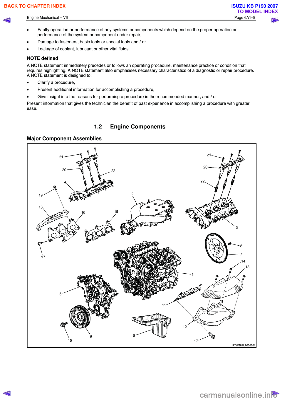
1.2 Engine Components
Major Component Assemblies
BACK TO CHAPTER INDEX
TO MODEL INDEX
ISUZU KB P190 2007