Page 2553 of 6020

Engine Mechanical – V6 Page 6A1–74
NOTE
If the lower intake manifold is cracked or
damaged, it must be replaced. No welding or
patching of the intake manifold should be
performed.
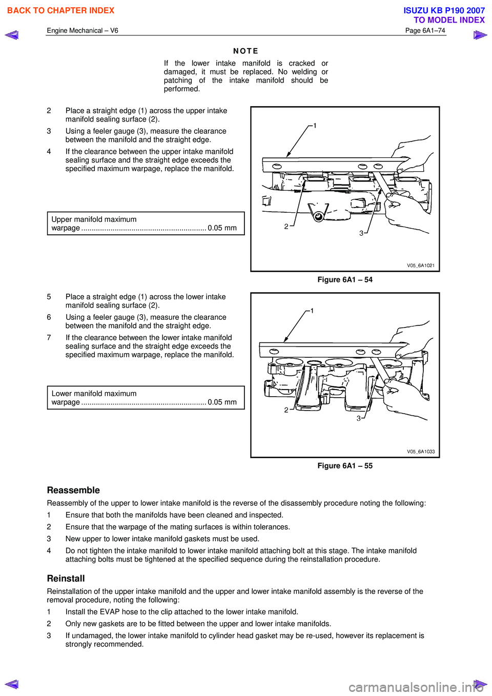
2 Place a straight edge (1) across the upper intake manifold sealing surface (2).
3 Using a feeler gauge (3), measure the clearance between the manifold and the straight edge.
4 If the clearance between the upper intake manifold sealing surface and the straight edge exceeds the
specified maximum warpage, replace the manifold.
Upper manifold maximum
warpage ............................................................ 0.05 mm
Figure 6A1 – 54
5 Place a straight edge (1) across the lower intake manifold sealing surface (2).
6 Using a feeler gauge (3), measure the clearance between the manifold and the straight edge.
7 If the clearance between the lower intake manifold sealing surface and the straight edge exceeds the
specified maximum warpage, replace the manifold.
Lower manifold maximum
warpage ............................................................ 0.05 mm
Figure 6A1 – 55
Reassemble
Reassembly of the upper to lower intake manifold is the reverse of the disassembly procedure noting the following:
1 Ensure that both the manifolds have been cleaned and inspected.
2 Ensure that the warpage of the mating surfaces is within tolerances.
3 New upper to lower intake manifold gaskets must be used.
4 Do not tighten the intake manifold to lower intake manifold attaching bolt at this stage. The intake manifold attaching bolts must be tightened at the specified sequence during the reinstallation procedure.
Reinstall
Reinstallation of the upper intake manifold and the upper and lower intake manifold assembly is the reverse of the
removal procedure, noting the following:
1 Install the EVAP hose to the clip attached to the lower intake manifold.
2 Only new gaskets are to be fitted between the upper and lower intake manifolds.
3 If undamaged, the lower intake manifold to cylinder head gasket may be re-used, however its replacement is strongly recommended.
BACK TO CHAPTER INDEX
TO MODEL INDEX
ISUZU KB P190 2007
Page 2573 of 6020

Engine Mechanical – V6 Page 6A1–94
3.16 Timing Chains, Tensioners, Shoes and
Guides
CAUTION
Setting the camshaft timing is required
whenever the camshaft drive system has
been disturbed and the relationship between
any chain and sprocket has been lost. If
required, follow the left-hand secondary
timing chain reinstallation procedure to reset
the camshaft timing.
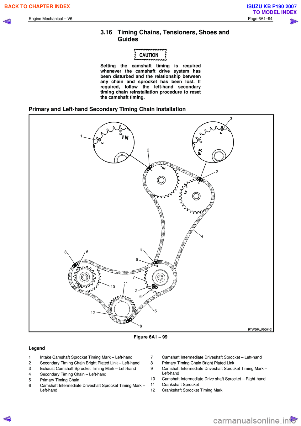
Primary and Left-hand Secondary Timing Chain Installation
Figure 6A1 – 99
Legend
1 Intake Camshaft Sprocket Timing Mark – Left-hand
2 Secondary Timing Chain Bright Plated Link – Left-hand
3 Exhaust Camshaft Sprocket Timing Mark – Left-hand
4 Secondary Timing Chain – Left-hand
5 Primary Timing Chain
6 Camshaft Intermediate Driveshaft Sprocket Timing Mark – Left-hand 7 Camshaft Intermediate Driveshaft Sprocket – Left-hand
8 Primary Timing Chain Bright Plated Link
9 Camshaft Intermediate Driveshaft Sprocket Timing Mark – Left-hand
10 Camshaft Intermediate Drive shaft Sprocket – Right-hand
11 Crankshaft Sprocket
12 Crankshaft Sprocket Timing Mark
BACK TO CHAPTER INDEX
TO MODEL INDEX
ISUZU KB P190 2007
Page 2574 of 6020
Engine Mechanical – V6 Page 6A1–95
Right-hand Secondary Timing Chain Installation
Figure 6A1 – 100
Legend
1 Intake Camshaft Sprocket Timing Mark – Left-hand
2 Secondary Timing Chain Bright Plated Link – Left-hand
3 Exhaust Camshaft Sprocket Timing Mark – Left-hand
4 Secondary Timing Chain – Left-hand
5 Primary Timing chain
6 Camshaft Intermediate Drive Chain Sprocket Timing Mark – Left-hand
7 Primary Camshaft Intermediate Drive Chain Sprocket – Left- hand
8 Primary Timing Chain Bright Plated Link 9 Camshaft Intermediate Drive Chain Sprocket Timing Mark –
Left-hand
10 Camshaft Intermediate Drive Chain Sprocket – Right-hand
11 Crankshaft Sprocket
12 Crankshaft Sprocket Timing Mark
13 Secondary Timing chain Bright Plated Link – Right-hand
14 Camshaft Intermediate Drive Chain – Right-hand
15 Exhaust Camshaft Sprocket Timing Mark - Right-side
16 Inlet Camshaft Sprocket Timing Mark - Right-side
BACK TO CHAPTER INDEX
TO MODEL INDEX
ISUZU KB P190 2007
Page 2575 of 6020
Engine Mechanical – V6 Page 6A1–96
Remove
Right-hand Secondary Timing Chain
CAUTION
After removing the upper intake manifold, and
spark plugs, plug any openings to prevent dirt
and other contaminants from entering.
1 Remove the engine front cover assembly, refer to 3.15 Front Cover Assembly.
2 Remove the spark plugs to aid crankshaft/engine rotation, refer to 6C1-3 Engine Management – V6 – Service Operations.
3 Install Tool No. EN46111 (1) onto the crankshaft (2).
Figure 6A1 – 101
4 Using Tool No. EN46111 (1), rotate the crankshaft in a clockwise direction until the crankshaft sprocket
timing mark (2) is aligned with the indexing mark (3)
on the oil pump housing.
Figure 6A1 – 102
BACK TO CHAPTER INDEX
TO MODEL INDEX
ISUZU KB P190 2007
Page 2577 of 6020
Engine Mechanical – V6 Page 6A1–98
9 Remove the right-hand secondary timing chain
tensioner bolts (1) and remove the tensioner (2).
NOTE
Take care when removing the tensioner bolts.
The tensioner plunger is subjected to spring
tension and may spring apart during tensioner
removal.
Figure 6A1 – 106
10 Remove the tensioner gasket (1) from the tensioner (2) and discard the gasket.
11 Inspect the tensioner mounting surface on the right- hand cylinder head for burrs or any defects that would
affect the sealing of a new tensioner gasket.
Figure 6A1 – 107
12 Remove the right-hand secondary timing chain shoe bolt (1).
Figure 6A1 – 108
BACK TO CHAPTER INDEX
TO MODEL INDEX
ISUZU KB P190 2007
Page 2578 of 6020
Engine Mechanical – V6 Page 6A1–99
13 Remove the right-hand secondary timing chain shoe
(1).
Figure 6A1 – 109
14 Remove the two right-hand secondary timing chain guide bolts (1) and remove the guide (2).
Figure 6A1 – 110
15 Remove the right-hand secondary timing chain (1) from the camshaft position actuators (2) and the
camshaft intermediate driveshaft sprocket (3).
Figure 6A1 – 111
BACK TO CHAPTER INDEX
TO MODEL INDEX
ISUZU KB P190 2007
Page 2579 of 6020
Engine Mechanical – V6 Page 6A1–100
Primary Timing Chain
1 Remove the right-hand secondary timing chain, refer to Right-hand Secondary Timing Chain in this Section.
2 Remove the two primary timing chain tensioner bolts (1), and remove the tensioner (2).
NOTE
Take care when removing the tensioner bolts.
The tensioner plunger is subjected to spring
tension and may spring apart during tensioner
removal.
Figure 6A1 – 112
3 Remove the gasket (1) from the tensioner (2) and discard the gasket.
4 Inspect the primary timing chain tensioner mounting surface on the engine block for burrs or any defects
that would affect the sealing of a new tensioner
gasket.
Figure 6A1 – 113
5 Remove the two primary timing chain upper guide bolts (1) and remove the guide (2).
Figure 6A1 – 114
BACK TO CHAPTER INDEX
TO MODEL INDEX
ISUZU KB P190 2007
Page 2581 of 6020
Engine Mechanical – V6 Page 6A1–102
8 If required, remove the crankshaft sprocket (1) from
the crankshaft (2).
Figure 6A1 – 118
Left-hand Secondary Timing Chain
1 Remove the primary timing chain, refer to Primary Timing Chain in this Section.
2 Remove the two left-hand secondary timing chain tensioner bolts (1) and remove the tensioner (2).
NOTE
Take care when removing the tensioner bolts.
The tensioner plunger is subjected to spring
tension and may spring apart during tensioner
removal.
Figure 6A1 – 119
3 Remove the gasket (1) from the tensioner (2) and discard the gasket.
4 Inspect the tensioner mounting surface on the left- hand cylinder head for burrs or any defects that would
affect the sealing of a new tensioner gasket.
Figure 6A1 – 120
BACK TO CHAPTER INDEX
TO MODEL INDEX
ISUZU KB P190 2007