2007 ISUZU KB P190 ECO mode
[x] Cancel search: ECO modePage 2615 of 6020
Engine Mechanical – V6 Page 6A1–136
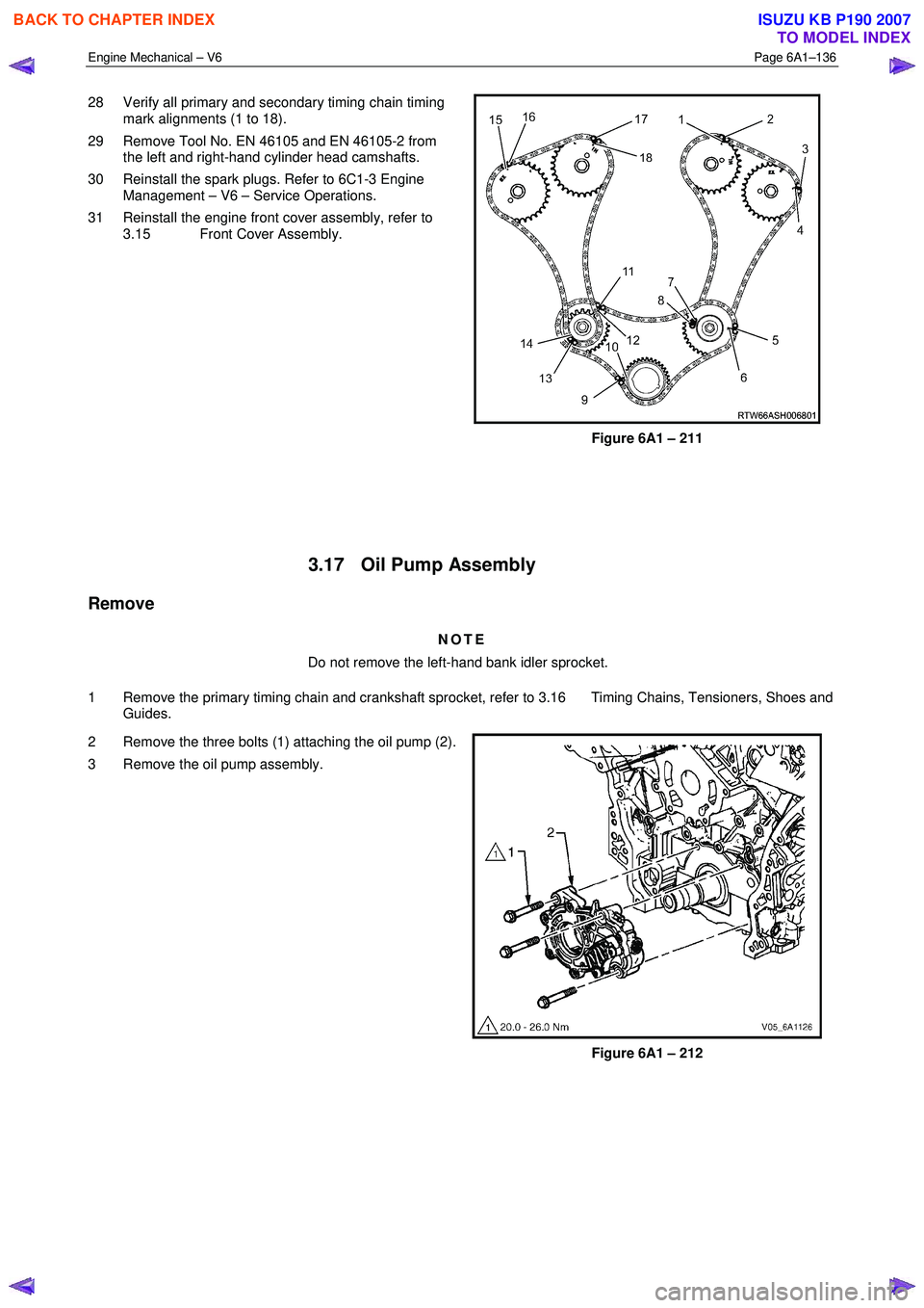
28 Verify all primary and secondary timing chain timing
mark alignments (1 to 18).
29 Remove Tool No. EN 46105 and EN 46105-2 from the left and right-hand cylinder head camshafts.
30 Reinstall the spark plugs. Refer to 6C1-3 Engine Management – V6 – Service Operations.
31 Reinstall the engine front cover assembly, refer to 3.15 Front Cover Assembly.
Figure 6A1 – 211
3.17 Oil Pump Assembly
Remove
NOTE
Do not remove the left-hand bank idler sprocket.
1 Remove the primary timing chain and crankshaft sprocket, refer to 3.16 Timing Chains, Tensioners, Shoes and Guides.
2 Remove the three bolts (1) attaching the oil pump (2).
3 Remove the oil pump assembly.
Figure 6A1 – 212
BACK TO CHAPTER INDEX
TO MODEL INDEX
ISUZU KB P190 2007
Page 2620 of 6020
Engine Mechanical – V6 Page 6A1–141
Reassemble
CAUTION
As there are no serviceable components
within the oil pump, a disassembled oil pump
must be replaced.
Reinstall
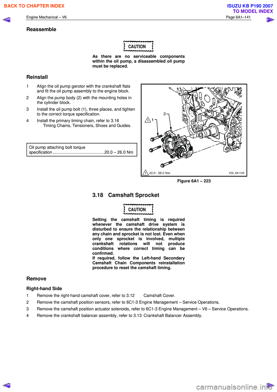
1 Align the oil pump gerotor with the crankshaft flats and fit the oil pump assembly to the engine block.
2 Align the pump body (2) with the mounting holes in the cylinder block.
3 Install the oil pump bolt (1), three places, and tighten to the correct torque specification.
4 Install the primary timing chain, refer to 3.16 Timing Chains, Tensioners, Shoes and Guides.
Oil pump attaching bolt torque
specification ............................................20.0 – 26.0 Nm
Figure 6A1 – 223
3.18 Camshaft Sprocket
CAUTION
Setting the camshaft timing is required
whenever the camshaft drive system is
disturbed to ensure the relationship between
any chain and sprocket is not lost. Even when
only one sprocket is involved, multiple
crankshaft rotations will not produce
conditions where correct timing can be
confirmed.
If required, follow the Left-hand Secondary
Camshaft Chain Components reinstallation
procedure to reset the camshaft timing.
Remove
Right-hand Side
1 Remove the right-hand camshaft cover, refer to 3.12 Camshaft Cover.
2 Remove the camshaft position sensors, refer to 6C1-3 Engine Management – Service Operations.
3 Remove the camshaft position actuator solenoids, refer to 6C1-3 Engine Management – V6 – Service Operations.
4 Remove the crankshaft balancer assembly, refer to 3.13 Crankshaft Balancer Assembly.
BACK TO CHAPTER INDEX
TO MODEL INDEX
ISUZU KB P190 2007
Page 2637 of 6020
Engine Mechanical – V6 Page 6A1–158
3.20 Rocker Arm
Remove
1 Remove the camshafts from the appropriate cylinder head, refer to 3.19 Camshaft.
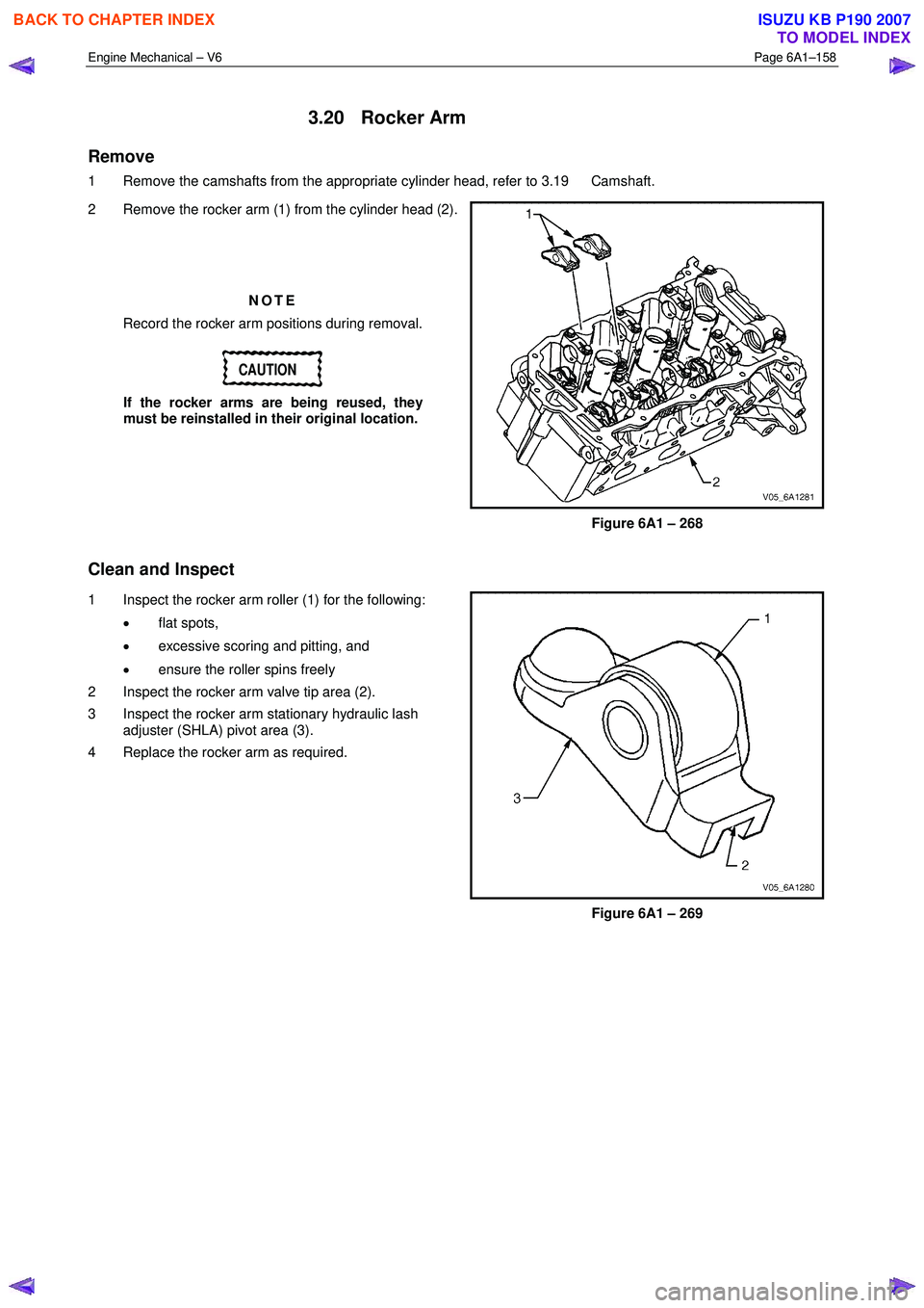
2 Remove the rocker arm (1) from the cylinder head (2).
NOTE
Record the rocker arm positions during removal.
CAUTION
If the rocker arms are being reused, they
must be reinstalled in their original location.
Figure 6A1 – 268
Clean and Inspect
1 Inspect the rocker arm roller (1) for the following:
• flat spots,
• excessive scoring and pitting, and
• ensure the roller spins freely
2 Inspect the rocker arm valve tip area (2).
3 Inspect the rocker arm stationary hydraulic lash adjuster (SHLA) pivot area (3).
4 Replace the rocker arm as required.
Figure 6A1 – 269
BACK TO CHAPTER INDEX
TO MODEL INDEX
ISUZU KB P190 2007
Page 2640 of 6020
Engine Mechanical – V6 Page 6A1–161
Reinstall
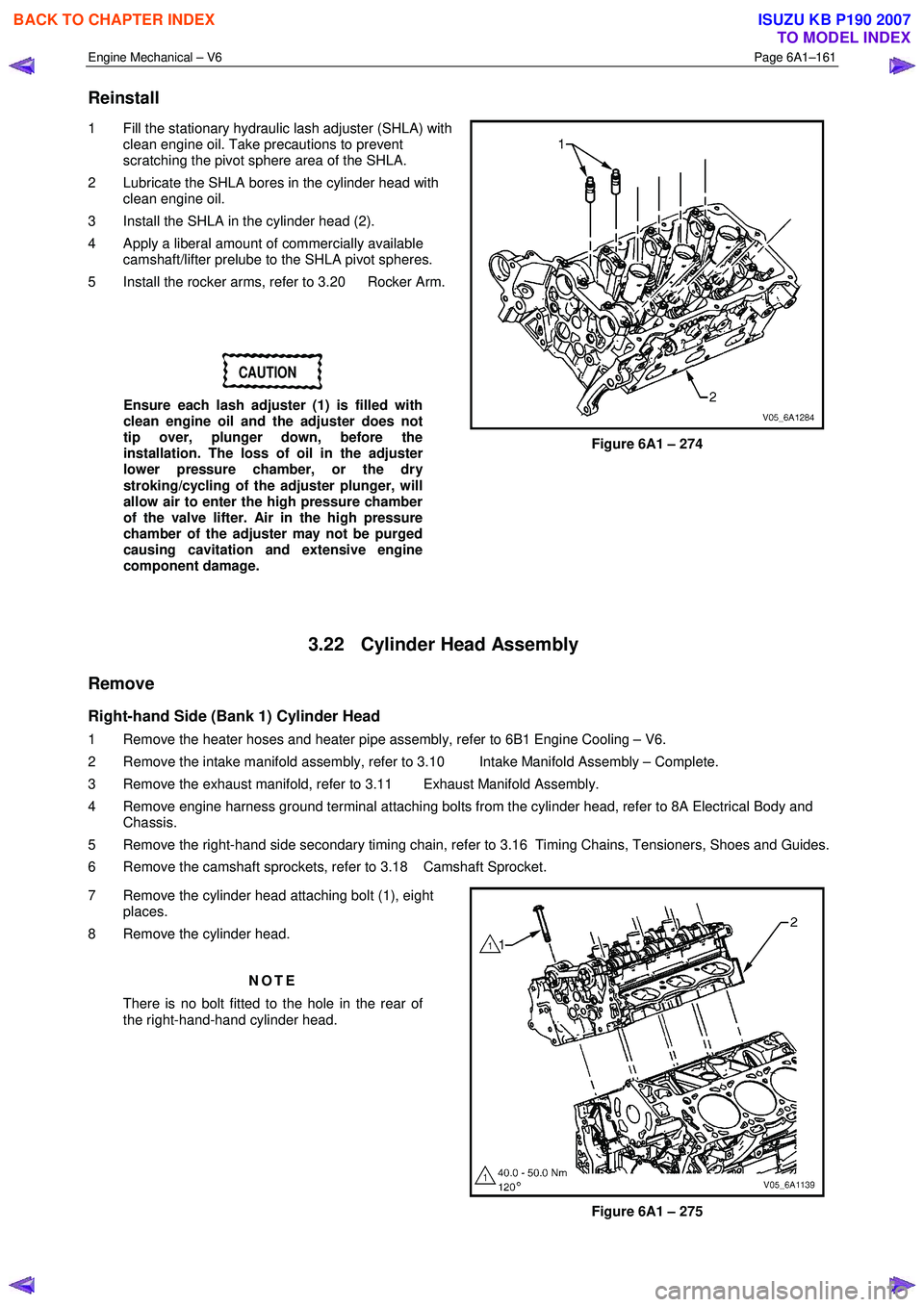
1 Fill the stationary hydraulic lash adjuster (SHLA) with
clean engine oil. Take precautions to prevent
scratching the pivot sphere area of the SHLA.
2 Lubricate the SHLA bores in the cylinder head with clean engine oil.
3 Install the SHLA in the cylinder head (2).
4 Apply a liberal amount of commercially available camshaft/lifter prelube to the SHLA pivot spheres.
5 Install the rocker arms, refer to 3.20 Rocker Arm.
CAUTION
Ensure each lash adjuster (1) is filled with
clean engine oil and the adjuster does not
tip over, plunger down, before the
installation. The loss of oil in the adjuster
lower pressure chamber, or the dry
stroking/cycling of the adjuster plunger, will
allow air to enter the high pressure chamber
of the valve lifter. Air in the high pressure
chamber of the adjuster may not be purged
causing cavitation and extensive engine
component damage.
Figure 6A1 – 274
3.22 Cylinder Head Assembly
Remove
Right-hand Side (Bank 1) Cylinder Head
1 Remove the heater hoses and heater pipe assembly, refer to 6B1 Engine Cooling – V6.
2 Remove the intake manifold assembly, refer to 3.10 Intake Manifold Assembly – Complete.
3 Remove the exhaust manifold, refer to 3.11 Exhaust Manifold Assembly.
4 Remove engine harness ground terminal attaching bolts from the cylinder head, refer to 8A Electrical Body and Chassis.
5 Remove the right-hand side secondary timing chain, refer to 3.16 Timing Chains, Tensioners, Shoes and Guides.
6 Remove the camshaft sprockets, refer to 3.18 Camshaft Sprocket.
7 Remove the cylinder head attaching bolt (1), eight places.
8 Remove the cylinder head.
NOTE
There is no bolt fitted to the hole in the rear of
the right-hand-hand cylinder head.
Figure 6A1 – 275
BACK TO CHAPTER INDEX
TO MODEL INDEX
ISUZU KB P190 2007
Page 2641 of 6020
Engine Mechanical – V6 Page 6A1–162
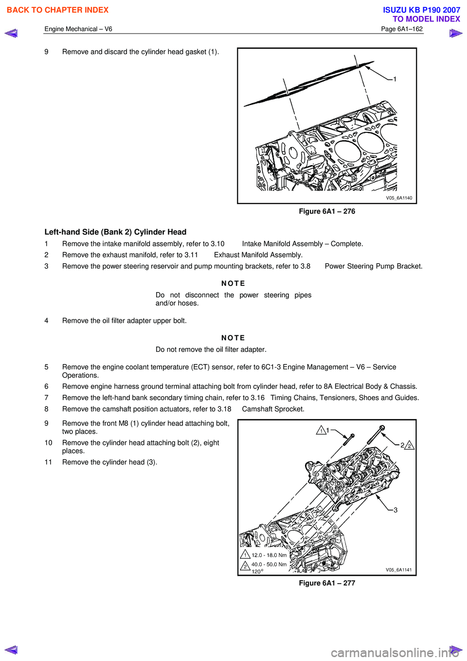
9 Remove and discard the cylinder head gasket (1).
Figure 6A1 – 276
Left-hand Side (Bank 2) Cylinder Head
1 Remove the intake manifold assembly, refer to 3.10 Intake Manifold Assembly – Complete.
2 Remove the exhaust manifold, refer to 3.11 Exhaust Manifold Assembly.
3 Remove the power steering reservoir and pump mounting brackets, refer to 3.8 Power Steering Pump Bracket.
NOTE
Do not disconnect the power steering pipes
and/or hoses.
4 Remove the oil filter adapter upper bolt. NOTE
Do not remove the oil filter adapter.
5 Remove the engine coolant temperature (ECT) sensor, refer to 6C1-3 Engine Management – V6 – Service Operations.
6 Remove engine harness ground terminal attaching bolt from cylinder head, refer to 8A Electrical Body & Chassis.
7 Remove the left-hand bank secondary timing chain, refer to 3.16 Timing Chains, Tensioners, Shoes and Guides.
8 Remove the camshaft position actuators, refer to 3.18 Camshaft Sprocket.
9 Remove the front M8 (1) cylinder head attaching bolt, two places.
10 Remove the cylinder head attaching bolt (2), eight places.
11 Remove the cylinder head (3).
Figure 6A1 – 277
BACK TO CHAPTER INDEX
TO MODEL INDEX
ISUZU KB P190 2007
Page 2646 of 6020
Engine Mechanical – V6 Page 6A1–167
Inspect
Visual Inspection
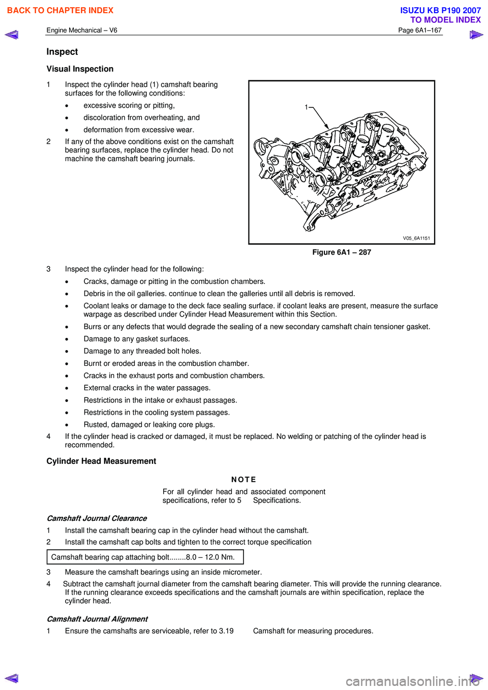
1 Inspect the cylinder head (1) camshaft bearing
surfaces for the following conditions:
• excessive scoring or pitting,
• discoloration from overheating, and
• deformation from excessive wear.
2 If any of the above conditions exist on the camshaft bearing surfaces, replace the cylinder head. Do not
machine the camshaft bearing journals.
Figure 6A1 – 287
3 Inspect the cylinder head for the following: • Cracks, damage or pitting in the combustion chambers.
• Debris in the oil galleries. continue to clean the galleries until all debris is removed.
• Coolant leaks or damage to the deck face sealing surface. if coolant leaks are present, measure the surface
warpage as described under Cylinder Head Measurement within this Section.
• Burrs or any defects that would degrade the sealing of a new secondary camshaft chain tensioner gasket.
• Damage to any gasket surfaces.
• Damage to any threaded bolt holes.
• Burnt or eroded areas in the combustion chamber.
• Cracks in the exhaust ports and combustion chambers.
• External cracks in the water passages.
• Restrictions in the intake or exhaust passages.
• Restrictions in the cooling system passages.
• Rusted, damaged or leaking core plugs.
4 If the cylinder head is cracked or damaged, it must be replaced. No welding or patching of the cylinder head is recommended.
Cylinder Head Measurement
NOTE
For all cylinder head and associated component
specifications, refer to 5 Specifications.
Camshaft Journal Clearance
1 Install the camshaft bearing cap in the cylinder head without the camshaft.
2 Install the camshaft cap bolts and tighten to the correct torque specification
Camshaft bearing cap attaching bolt........8.0 – 12.0 Nm.
3 Measure the camshaft bearings using an inside micrometer.
4 Subtract the camshaft journal diameter from the camshaft bearing diameter. This will provide the running clearance. If the running clearance exceeds specifications and the camshaft journals are within specification, replace the
cylinder head.
Camshaft Journal Alignment
1 Ensure the camshafts are serviceable, refer to 3.19 Camshaft for measuring procedures.
BACK TO CHAPTER INDEX
TO MODEL INDEX
ISUZU KB P190 2007
Page 2649 of 6020
Engine Mechanical – V6 Page 6A1–170
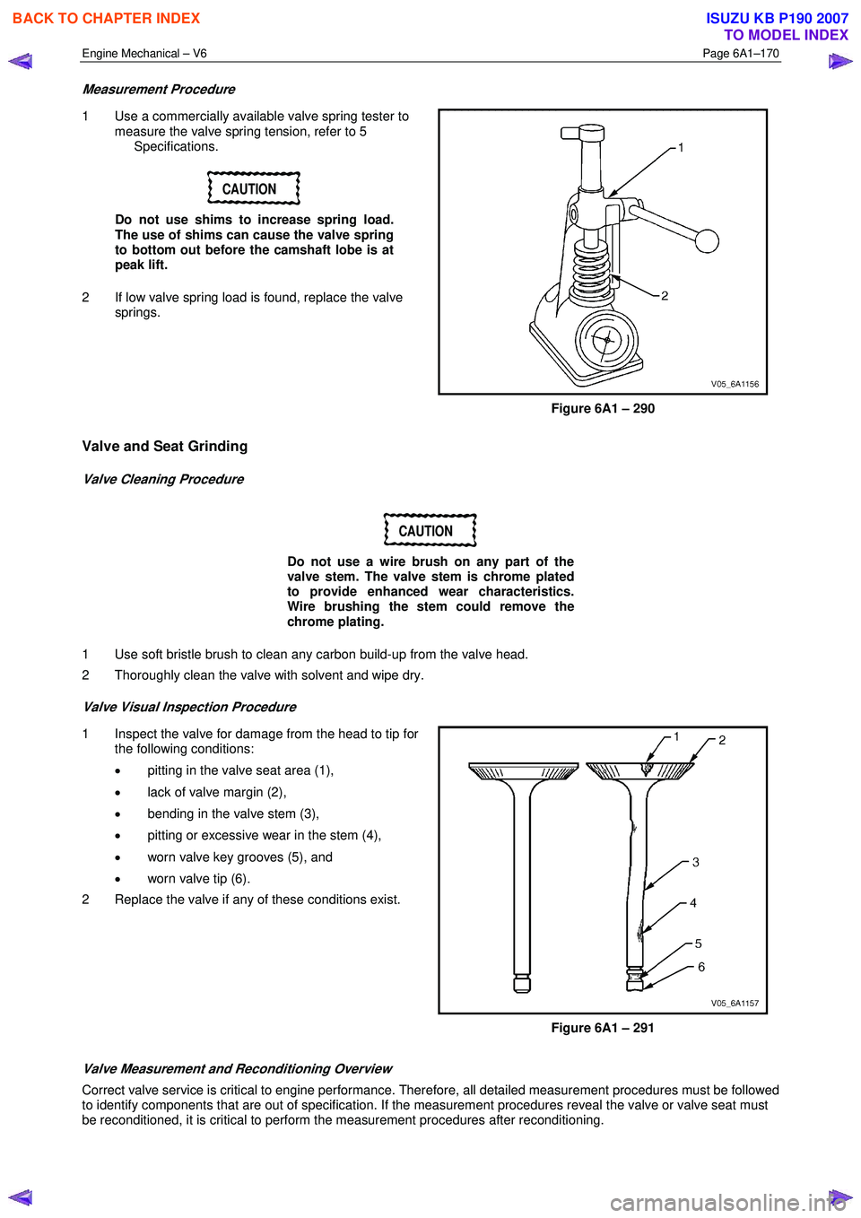
Measurement Procedure
1 Use a commercially available valve spring tester to
measure the valve spring tension, refer to 5
Specifications.
CAUTION
Do not use shims to increase spring load.
The use of shims can cause the valve spring
to bottom out before the camshaft lobe is at
peak lift.
2 If low valve spring load is found, replace the valve springs.
Figure 6A1 – 290
Valve and Seat Grinding
Valve Cleaning Procedure
CAUTION
Do not use a wire brush on any part of the
valve stem. The valve stem is chrome plated
to provide enhanced wear characteristics.
Wire brushing the stem could remove the
chrome plating.
1 Use soft bristle brush to clean any carbon build-up from the valve head.
2 Thoroughly clean the valve with solvent and wipe dry.
Valve Visual Inspection Procedure
1 Inspect the valve for damage from the head to tip for the following conditions:
• pitting in the valve seat area (1),
• lack of valve margin (2),
• bending in the valve stem (3),
• pitting or excessive wear in the stem (4),
• worn valve key grooves (5), and
• worn valve tip (6).
2 Replace the valve if any of these conditions exist.
Figure 6A1 – 291
Valve Measurement and Reconditioning Overview
Correct valve service is critical to engine performance. Therefore, all detailed measurement procedures must be followed
to identify components that are out of specification. If the measurement procedures reveal the valve or valve seat must
be reconditioned, it is critical to perform the measurement procedures after reconditioning.
BACK TO CHAPTER INDEX
TO MODEL INDEX
ISUZU KB P190 2007
Page 2650 of 6020
Engine Mechanical – V6 Page 6A1–171
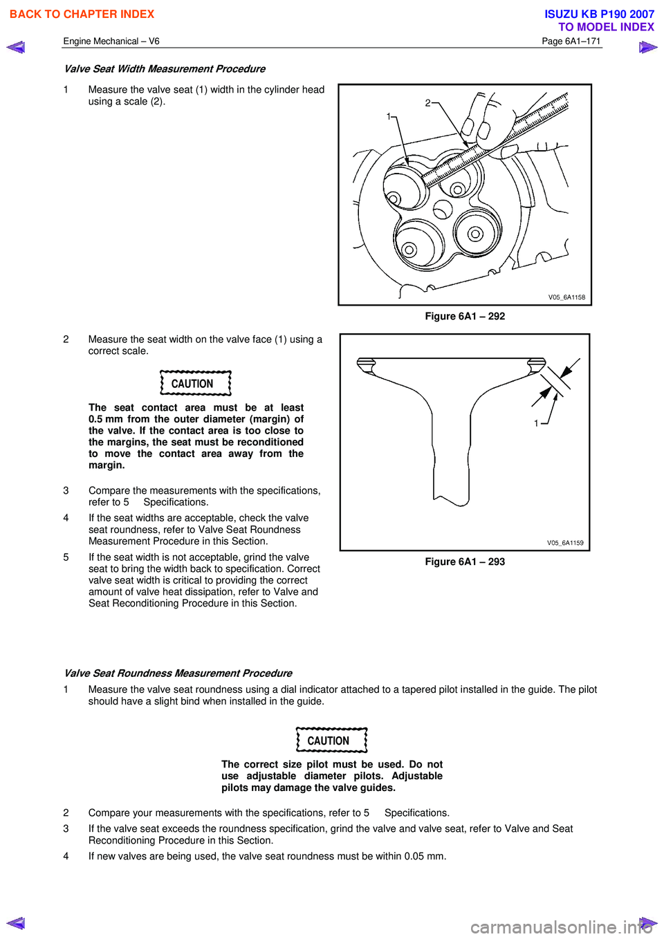
Valve Seat Width Measurement Procedure
1 Measure the valve seat (1) width in the cylinder head
using a scale (2).
Figure 6A1 – 292
2 Measure the seat width on the valve face (1) using a correct scale.
CAUTION
The seat contact area must be at least
0.5 mm from the outer diameter (margin) of
the valve. If the contact area is too close to
the margins, the seat must be reconditioned
to move the contact area away from the
margin.
3 Compare the measurements with the specifications, refer to 5 Specifications.
4 If the seat widths are acceptable, check the valve seat roundness, refer to Valve Seat Roundness
Measurement Procedure in this Section.
5 If the seat width is not acceptable, grind the valve seat to bring the width back to specification. Correct
valve seat width is critical to providing the correct
amount of valve heat dissipation, refer to Valve and
Seat Reconditioning Procedure in this Section.
Figure 6A1 – 293
Valve Seat Roundness Measurement Procedure
1 Measure the valve seat roundness using a dial indicator attached to a tapered pilot installed in the guide. The pilot should have a slight bind when installed in the guide.
CAUTION
The correct size pilot must be used. Do not
use adjustable diameter pilots. Adjustable
pilots may damage the valve guides.
2 Compare your measurements with the specifications, refer to 5 Specifications.
3 If the valve seat exceeds the roundness specification, grind the valve and valve seat, refer to Valve and Seat Reconditioning Procedure in this Section.
4 If new valves are being used, the valve seat roundness must be within 0.05 mm.
BACK TO CHAPTER INDEX
TO MODEL INDEX
ISUZU KB P190 2007