2007 ISUZU KB P190 ECO mode
[x] Cancel search: ECO modePage 2781 of 6020
Engine Mechanical – V6 Page 6A1–4
Page 6A1–4
Reinstall ................................................................................................................................................................ 97
3.13 Crankshaft Balancer Assembly ................................................................................................... .....................100
Remove ............................................................................................................................................................... 100
Clean and Inspect .............................................................................................................. ................................101
Reinstall .............................................................................................................................................................. 101
3.14 Crankshaft Front Seal.......................................................................................................... ..............................103
Replace ........................................................................................................................ .......................................103
3.15 Front Cover Assembly........................................................................................................... ............................104
Remove ............................................................................................................................................................... 104
Disassemble ....................................................................................................................................................... 105
Clean................................................................................................................................................................... 106
Inspect ........................................................................................................................ ........................................107
Reassemble ........................................................................................................................................................ 107
Reinstall .............................................................................................................................................................. 108
3.16 Timing Chains, Tensioners, Shoes and Guides .................................................................................... ..........110
Primary and Left-hand Secondary Timing Chain Installation ...................................................................... ..110
Excluding MY 06 Update .......................................................................................................... .......................110
MY06 Update .................................................................................................................... .............................111
Right-hand Secondary Timi ng Chain Installation ........................................................................................... 112
Excluding MY06 Update .......................................................................................................... .......................112
MY06 Update .................................................................................................................... .............................113
Remove ............................................................................................................................................................... 114
Right-hand Secondary Timing Chain.............................................................................................. ................114
Primary Timi ng Chain ........................................................................................................... ..........................118
Left-hand Secondary Timing C hain ............................................................................................... .................120
Clean................................................................................................................................................................... 123
Inspect ........................................................................................................................ ........................................124
Timing Chains .................................................................................................................. ..............................124
Camshaft Intermedi ate Sprockets .................................................................................................................. 124
Inlet and Exhaust Camshaft Sprocket ............................................................................................ ................124
Crankshaft Sprocket ....................................................................................................................................... 125
Primary Timing Chain Upper Guide............................................................................................... .................125
Primary Timing C hain Lower Guide............................................................................................... .................125
Primary Timing C hain Tensioner ................................................................................................. ...................126
Left-hand Secondary Ti ming Chain Guide ......................................................................................... ............126
Left-hand Secondary Ti ming Chain Shoe.......................................................................................... .............127
Left-hand Secondary Timi ng Chain Tensioner ..................................................................................... ..........127
Right-hand Sec ondary Timing Chain Guide ................................................................................................... 128
Right-hand Secondary Timing Chain Shoe ......................................................................................... ...........128
Right-hand Se condary Timing Chain Tensioner .................................................................................... .........129
Reinst all .............................................................................................................................................................. 130
Left-hand Secondary Timing Chain Components – Excluding MY06 Update ................................................ 130
Left-hand Secondary Timing Chain Components – MY06 Update ................................................................. 139
Primary Timing Chain Components – Excluding MY06 Update ..................................................................... 149
Primary Timing Chain Components – MY06 Update .................................................................................. ....156
Right-hand Secondary Timing Chain Components – Excluding MY06 Update .............................................. 164
Right-hand Secondary Timing Chain Components – MY06 Update............................................................... 171
3.17 Oil Pump Assembly .............................................................................................................. .............................180
Remove ............................................................................................................................................................... 180
Disassemble ....................................................................................................................................................... 181
Clean................................................................................................................................................................... 182
Inspect ........................................................................................................................ ........................................183
Reassemble ........................................................................................................................................................ 185
Reinstall .............................................................................................................................................................. 185
3.18 Camshaft Sprocket – Excluding MY06 Update ................................................................................................ 186
Remove ............................................................................................................................................................... 186
Right-hand Side................................................................................................................ ..............................186
Left-hand Side ................................................................................................................................................ 189
Clean................................................................................................................................................................... 191
Inspect ........................................................................................................................ ........................................191
BACK TO CHAPTER INDEX
TO MODEL INDEX
ISUZU KB P190 2007
Page 2785 of 6020
Engine Mechanical – V6 Page 6A1–8
Page 6A1–8
1 General Information
The HFV6 engine features a closed vee, deep skirt die cast aluminium cylinder block with cast iron cylinder liners,
internally balanced crankcase, full length wa ter jackets and six bolt main bearing caps.
The cylinders are arranged in two banks of three with a 60 degree included angle between the two banks.
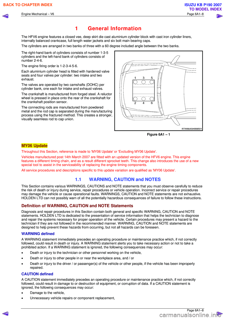
The right-hand bank of cylinders consists of number 1-3-5
cylinders and the left-hand bank of cylinders consists of
number 2-4-6.
The engine firing order is 1-2-3-4-5-6.
Each aluminium cylinder head is fitted with hardened valve
seats and four valves per cylinder: two intake and two
exhaust.
The valves are operated by two camshafts (DOHC) per
cylinder bank, one each for intake and exhaust valves.
The crankshaft is manufactured from forged steel. A reluctor
wheel is pressed in place onto the rear of the crankshaft for
the crankshaft position sensor.
The connecting rods are m anufactured from powdered
metal and the rod cap is separ ated during the manufacturing
process using the fractured me thod. This creates a stronger,
visually seamless rod to cap union.
Figure 6A1 – 1
MY06 Update
Throughout this Section, reference is made to 'MY06 Update' or 'Excluding MY06 Update'.
Vehicles manufactured post 14th Marc h 2007 are fitted with an updated version of the HFV6 engine. This engine
features a different timing chain, and as a result different sprocket teeth. This change also introduces the use of a new
special tool to assist in the serviceab ility of replacing the engine timing components.
All service procedures and descriptions specific to this update variation are qualified as 'MY06 Update'.
1.1 WARNING, CAUTION and NOTES
This Section contains various WARNING S, CAUTIONS and NOTE statements that y ou must observe carefully to reduce
the risk of death or injury during servic e, repair procedures or vehicle operation. Incorrect service or repair procedures
may damage the vehicle or cause operat ional faults. WARNINGS, CAUTION and NOTE statements are not exhaustive.
HOLDEN LTD can not possibly warn of a ll the potentially hazardous consequences of failure to follow these instructions.
Definition of WARNING, CAUTION and NOTE Statements
Diagnosis and repair procedures in this Section contain both general and specific WARNING, CAUTION and NOTE
statements. HOLDEN LTD is dedicated to the presentation of service information that helps the technician to diagnose
and repair the systems necessary for proper operation of the vehicle. Certain procedures may present a hazard to the
technician if they are not followed in the reco mmended manner. WARNING, CAUTION and NOTE statements are
designed to help prevent these hazards from o ccurring, but not all hazards can be foreseen.
WARNING defined
A WARNING statement immediately precedes an operating procedure or maint enance practice which, if not correctly
followed, could result in death or injury . A WARNING statement alerts you to ta ke necessary action or not to take a
prohibited action. If a WARNING statement is ignored, the following consequences may occur:
• Death or injury to the technician or other personnel working on the vehicle,
• Death or injury to other people in or near the workplace area, and / or
• Death or injury to the driver / or passenger(s) of the vehicle or other people, if the vehicle has been improperly
repaired.
CAUTION defined
A CAUTION statement immediately prec edes an operating procedure or maintenance practice which, if not correctly
followed, could result in damage to or destruction of equi pment, or corruption of data. If a CAUTION statement is
ignored, the following consequences may occur:
• Damage to the vehicle,
• Unnecessary vehicle repairs or component replacement,
BACK TO CHAPTER INDEX
TO MODEL INDEX
ISUZU KB P190 2007
Page 2786 of 6020
Engine Mechanical – V6 Page 6A1–9
Page 6A1–9
• Faulty operation or performance of any system or component being repaired,
• Damage to any system or components which depend on the proper operation of the system or component being
repaired,
• Faulty operation or performance of any systems or components which depend on the proper operation or
performance of the system or component under repair,
• Damage to fasteners, basic tool s or special tools and / or
• Leakage of coolant, lubricant or other vital fluids.
NOTE defined
A NOTE statement immediatel y precedes or follows an operating procedure, maintenance practice or condition that
requires highlighting. A NOTE statement also emphasises necessary characte ristics of a diagnostic or repair procedure.
A NOTE statement is designed to:
• Clarify a procedure,
• Present additional information for accomplishing a procedure,
• Give insight into the reasons for performi ng a procedure in the recommended manner, and / or
Present information that gives the tec hnician the benefit of past experience in accomplishing a procedure with greater
ease.
BACK TO CHAPTER INDEX
TO MODEL INDEX
ISUZU KB P190 2007
Page 2790 of 6020
Engine Mechanical – V6 Page 6A1–13
Page 6A1–13
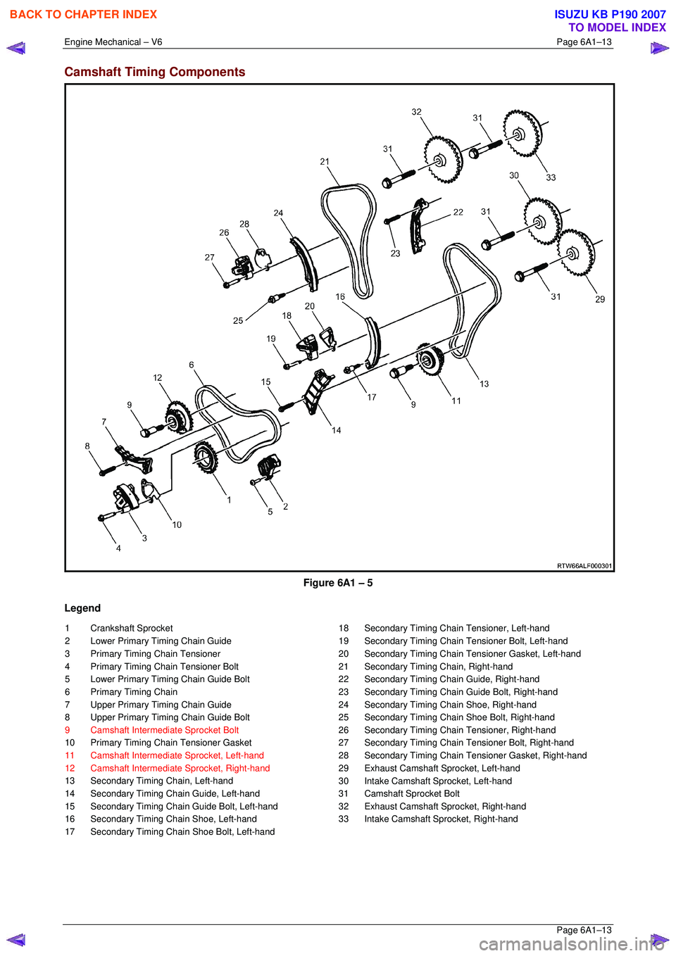
Camshaft Timing Components
Figure 6A1 – 5
Legend
1 Crankshaft Sprocket
2 Lower Primary Timing Chain Guide
3 Primary Timing Chain Tensioner
4 Primary Timing Chain Tensioner Bolt
5 Lower Primary Timing Chain Guide Bolt
6 Primary Timing Chain
7 Upper Primary Timing Chain Guide
8 Upper Primary Timing Chain Guide Bolt
9 Camshaft Intermediate Sprocket Bolt
10 Primary Timing Chain Tensioner Gasket
11 Camshaft Intermediate Sprocket, Left-hand
12 Camshaft Intermediate Sprocket, Right-hand
13 Secondary Timing Chain, Left-hand
14 Secondary Timing Chain Guide, Left-hand
15 Secondary Timing Chain Guide Bolt, Left-hand
16 Secondary Timing Chain Shoe, Left-hand
17 Secondary Timing Chain Shoe Bolt, Left-hand 18 Secondary Timing Chain Tensioner, Left-hand
19 Secondary Timing Chain Tensioner Bolt, Left-hand
20 Secondary Timing Chain Tensioner Gasket, Left-hand
21 Secondary Timing Chain, Right-hand
22 Secondary Timing Chain Guide, Right-hand
23 Secondary Timing Chain Guide Bolt, Right-hand
24 Secondary Timing Chain Shoe, Right-hand
25 Secondary Timing Chain Shoe Bolt, Right-hand
26 Secondary Timing Chai n Tensioner, Right-hand
27 Secondary Timing Chain Tensioner Bolt, Right-hand
28 Secondary Timing Chain T ensioner Gasket, Right-hand
29 Exhaust Camshaft Sprocket, Left-hand
30 Intake Camshaft Sprocket, Left-hand
31 Camshaft Sprocket Bolt
32 Exhaust Camshaft Sprocket, Right-hand
33 Intake Camshaft Sprocket, Right-hand
BACK TO CHAPTER INDEX
TO MODEL INDEX
ISUZU KB P190 2007
Page 2800 of 6020
Engine Mechanical – V6 Page 6A1–23
Page 6A1–23
Crankshaft
The crankshaft is a forged steel design with four main bearings. The number three main bearing controls crankshaft
thrust. A crankshaft position reluctor wheel is pressed onto the rear of the crankshaft, in front of the rear main journal.
The crankshaft is internally balanced with an integral oil pum p drive machined into the nose in front of the front main
journal.
Pistons, Pins and Connecting Rods
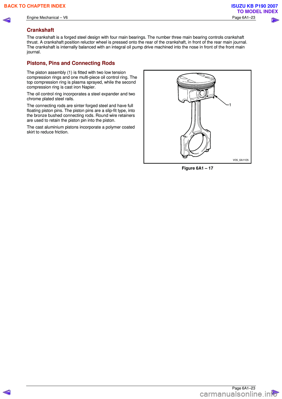
The piston assembly (1) is fitted with two low tension
compression rings and one multi-piece oil control ring. The
top compression ring is plasma sprayed, while the second
compression ring is cast iron Napier.
The oil control ring incorpor ates a steel expander and two
chrome plated steel rails.
The connecting rods are sint er forged steel and have full
floating piston pins. The piston pi ns are a slip-fit type, into
the bronze bushed connecting rods. Round wire retainers
are used to retain the piston pin into the piston.
The cast aluminium pistons incorporate a polymer coated
skirt to reduce friction.
Figure 6A1 – 17
BACK TO CHAPTER INDEX
TO MODEL INDEX
ISUZU KB P190 2007
Page 2801 of 6020
Engine Mechanical – V6 Page 6A1–24
Page 6A1–24
Camshaft Drive System
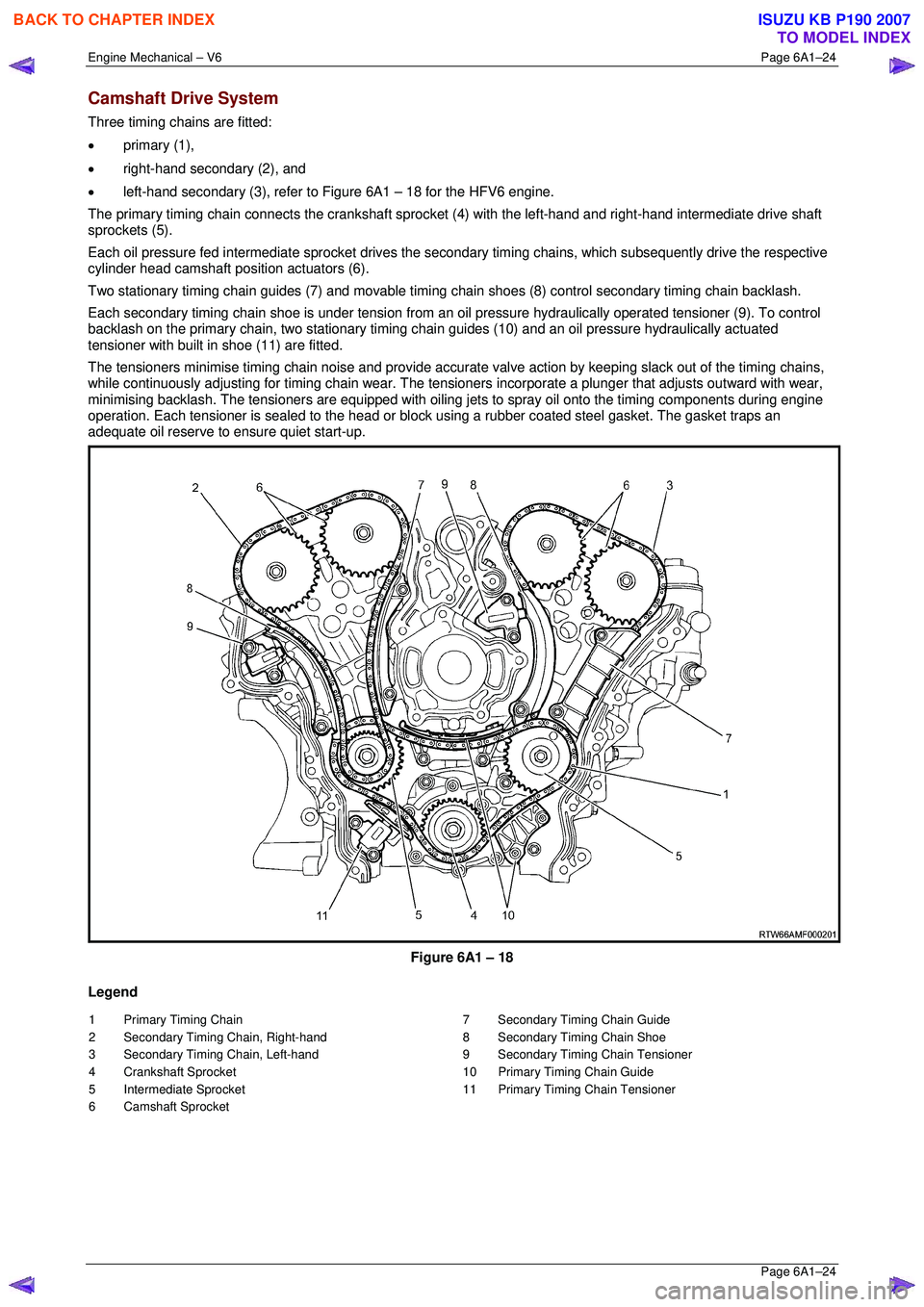
Three timing chains are fitted:
• primary (1),
• right-hand secondary (2), and
• left-hand secondary (3), refer to Figure 6A1 – 18 for the HFV6 engine.
The primary timing chain connects the crankshaft sprocket (4) with the left-hand and right-hand intermediate drive shaft
sprockets (5).
Each oil pressure fed intermediate sprocket drives the se condary timing chains, which subsequently drive the respective
cylinder head camshaft position actuators (6).
Two stationary timing chain guides (7) and movable timing c hain shoes (8) control secondary timing chain backlash.
Each secondary timing chain shoe is under tension from an oil pressure hydraulically operated tensioner (9). To control
backlash on the primary chain, two st ationary timing chain guides (10) and an oil pressure hydraulically actuated
tensioner with built in shoe (11) are fitted.
The tensioners minimise timing chain noise and provide accura te valve action by keeping slack out of the timing chains,
while continuously adjusting for timing chain wear. The tensioners incorporate a plunger that adjusts outward with wear,
minimising backlash. The tensioners are equipped with oiling jets to spray oil onto the timing components during engine
operation. Each tensioner is sealed to the head or block using a rubber coated steel gasket. The gasket traps an
adequate oil reserve to ens ure quiet start-up.
Figure 6A1 – 18
Legend
1 Primary Timing Chain
2 Secondary Timing Chain, Right-hand
3 Secondary Timing Chain, Left-hand
4 Crankshaft Sprocket
5 Intermediate Sprocket
6 Camshaft Sprocket 7 Secondary Timing Chain Guide
8 Secondary Timing Chain Shoe
9 Secondary Timing Chain Tensioner
10 Primary Timing Chain Guide
11 Primary Timing Chain Tensioner
BACK TO CHAPTER INDEX
TO MODEL INDEX
ISUZU KB P190 2007
Page 2802 of 6020
Engine Mechanical – V6 Page 6A1–25
Page 6A1–25
1.5 Engine Lubrication System
Lubrication Description
A structural diecast aluminium oil pan is fitted that incorporates an oil suction pipe, an oil deflector and an oil level
sensor. The oil suction pipe is bolted in to the oil pan and seals to the bottom of the cylinder block with a gasket. The oil
deflector is bolted to the upper portion of the oil pan and ensures oil supply is maintained under all conditions. The oil
level sensor is mounted thr ough the bottom of the oil pan.
A crankshaft driven gerotor oil pump is mounted to the front of the cylinder block. The pump, which incorporates an
internal pressure-relief valve, draws oil from the oil sucti on tube through the lower passage in the cylinder block. Oil is
then directed through an upper passage to the left-hand side of the cylinder block where the oil filter adapter is mounted.
The oil filter adapter incorporat es a top-access, cartridge style oil filter. The filter is accessed through a screw-on cap tha t
incorporates an oil bypass valve. The o il filter adapter housing incorporates a drain back control valve and a threaded oil
pressure sender. Oil flows through a lower passage within the oil filter adapter and through the o il filter cartridge. Filtered
oil travels back through the upper passage of the adapter and into the engine block.
Oil is then directed up and across the front of the cylinder block, through several drilled passages. These front passages
feed oil to each cylinder head, the passage for the main bearings and piston oil jets, the right-hand and left-hand
secondary idler sprockets and to t he primary timing chain tensioner.
Each cylinder head passage directs oil into oiling circuits for the stationary hydraulic la sh adjusters (SHLAs) and the
camshaft bearing journals. An additional passage in the cy linder head also directs oil to the secondary timing chain
tensioner.
The oil passage that supplies oil to the main bearings also s upplies oil to pressure actuated piston cooling oil jets. Each
oil jet is mounted between opposing cylinder bores and directs oil to the two bores to provide extra cooling and control
piston temperatures.
From the front passages, oil is directed to the front of the block where t he right-hand and left-hand intermediate drive
shaft sprockets and the primary timing chain tensioner are mounted. Each camshaft timing chain tensioner relies on a
gasket to maintain an oil rese rve after the engine is turned off. All camshaft timing chain tensioners incorporate a small
oil jet to supply an oil spray onto the camshaft timing chain components.
Oil returns to the oil pan, either through the camshaft timing chain area or through the drain back passages on the
outboard walls of the cylinder heads and cylinder block.
BACK TO CHAPTER INDEX
TO MODEL INDEX
ISUZU KB P190 2007
Page 2804 of 6020
Engine Mechanical – V6 Page 6A1–27
Page 6A1–27
Use of Room Temperature Vulcanising and Anaerobic Sealer
CAUTION
A number of sealant types are commonly
used in engines. Examples are; room
temperature vulcanising (RTV) sealer,
anaerobic gasket eliminator sealer, and
anaerobic thread sealant and pipe joint
compound. The correct type of sealant and
amount must be used in the specified location
to prevent oil leaks. Do not interchange the
different types of sealers.
Room Temperature Vulcanising Sealer
• Room temperature vulcanising (RTV) s ealant hardens when exposed to air. This type of sealer is used where two
non-rigid parts (such as the intake manifold and the engine block) are assembled together.
• Do not use RTV sealant in areas where extreme temper atures are experienced. These areas include the exhaust
manifold, head gasket, or other surfaces w here a gasket eliminator is specified.
• Follow all safety recommendations and di rections that are on the container.
• To remove the sealant or the gasket mate rial, refer to Replacing Engine Gaskets.
• Apply RTV to a clean surface. Use a bead size as specified in the service procedure. Run the bead to the inside of
any bolt holes. Do not allow the sealer to enter any bli nd threaded holes, as it may prevent the bolt from clamping
correctly or cause damage when the bolt is tightened.
• Assemble components while RTV is still wet (within 3 minutes). Do not wait for RTV to skin over.
• Tighten the bolts to the correct torque specification. Do not over-tighten.
Anaerobic Sealer
• Anaerobic gasket eliminator or thread sealant, hardens in t he absence of air. This type sealer is used where two
rigid parts (such as castings) are assembled together, w here fasteners are subjected to vibration, or where the
holes are not blind. When two rigid parts are disassembled and no sealer or gasket is readily noticeable, the parts
were probably assembled using a gasket eliminator.
• Follow all safety recommendations and di rections that are on the container.
• To remove the sealant or the gasket mate rial, refer to Replacing Engine Gaskets.
• Apply a continuous bead of gasket eliminator to one flange or on the bolt/stud thread. All surfaces must be clean
and dry.
• Spread the sealer evenly to achieve a uniform coating on the sealing surface.
• Do not allow the sealer to enter any blind threaded holes as it may prevent the bolt from clamping correctly or
cause damage when tightened.
CAUTION
Anaerobic sealed joints that are partially
tightened and allowed to cure more than five
minutes may result in incorrect shimming and
sealing of the joint.
• Tighten the bolts to the correct torque specification. Do not over-tighten.
• After correctly tightening the fasteners, remove t he excess sealer from the outside of the joint.
BACK TO CHAPTER INDEX
TO MODEL INDEX
ISUZU KB P190 2007