2007 ISUZU KB P190 ignition
[x] Cancel search: ignitionPage 1968 of 6020
ENGINE CONTROL SYSTEM (4JK1/4JJ1) 6E-351
Notice:If the ECM is replaced to new one, VIN does
not displayed. Input correct VIN reading from stamped
VIN or affixed VIN plate on the vehicle. If the ECM from
another vehicle is installed, input correct VIN by same
way.
g. Highlight Engine on the Select System Typescreen, then click "Next", if on-screen
instruction displayed.
h. Complete the following information based on the service ID plate on the Validate Vehicle
Data screen until "Next" is highlighted, then
click "Next".
• Model
• Model year
• Engine type
• Model designator
• Destination code
• Transmission type
i. Verify your selection on the Summary screen.
Notice: Refer to Service Bulletin and Description
column before service programming is performed if the
bulletins are listed along with the calibration files.
Notice: Select Cancel if you receive a message stating
that the calibration selected is already the current
calibration in the ECM and reprogramming with the
same download is not allowed.
j. Click "Reprog".
k. The Transfer Data screen will appear until the progress bar reaches 100%.
5. Close the application and return to the TIS application selection screen after the download is
completed.
6. Turn OFF the scan tool and disconnect from the terminal.
7. Transfer the data from the scan tool to the ECM using the following procedure:
a. Install a scan tool.
b. Turn ON the ignition, with the engine OFF.
c. Select Service Programming System (SPS) > Program ECU.
d. Turn OFF all accessories and press "Continue".
e. Programming in Process will appear until the progress bar reaches 100%.
Notice: Some warning lamp may turn ON or blink while
programming the ECM since communication between
the ECM and other modules are interrupted. Clear DTC
in any module after programming.
f. Press "Continue" and exit the program after thescan tool displays "Programming Was
Successful".
8. Turn OFF the ignition.
9. Turn OFF the scan tool and disconnect from the vehicle.Service Programming System (SPS) (Pass-
Thru Procedure)
Pass-Thru programming allows the scan tool to remain
connected to the terminal and to the vehicle throughout
the programming process. The vehicle must be in close
proximity to the terminal while using Pass-Thru.
1. Launch the TIS application.
2. Select the Service Programming System at the main screen.
3. Highlight the following information on the Select Diagnostic Tool and Programming Process screen,
then click "Next":
• Select Diagnostic Tool-Select Pass - Thru
• Select Programming Process - Identify whether as existing ECM is being reprogrammed or an
ECM is being replaced with a new one.
• Select ECU Location - Vehicle
4. Complete all vehicle data on the Preparing for Communication/ Determine Vehicle screen until
"Next" is highlighted, then click "Next".
5. Follow the instruction on the Preparing for Communication screen, then click "Next".
Notice: In order to reduce the potential for signal loss,
the RS-232 cable should not be more than 25 feet long.
6. Verify the VIN on the Validate Vehicle Identification Number (VIN) screen, then click "Next".
Notice: If the ECM is replaced to new one, VIN does
not displayed. Input correct VIN reading from stamped
VIN or affixed VIN plate on the vehicle. If the ECM from
another vehicle is installed, input correct VIN by same
way.
7. Highlight Engine on the Select System Type screen, then click "Next", if on-screen instruction
displayed.
8. Complete the following information based on the service ID plate on the Validate Vehicle Data
screen until "Next" is highlighted, then click "Next".
• Model
• Model year
• Engine type
• Model designator
• Destination code
• Transmission type
9. Verify your selection on the Summary screen.
Notice: Refer to Service Bulletin and Description
column before service programming is performed if the
bulletins are listed along with the calibration files.
Notice: Select Cancel if you receive a message stating
that the calibration selected is already the current
calibration in the ECM and reprogramming with the
same download is not allowed.
10. Click "Reprog".
BACK TO CHAPTER INDEX
TO MODEL INDEX
ISUZU KB P190 2007
Page 1969 of 6020
6E-352 ENGINE CONTROL SYSTEM (4JK1/4JJ1)
11. The Transfer Data screen will appear until theprogress bar reaches 100%.
Notice: Some warning lamp may turn ON or blink while
programming the ECM since communication between
the ECM and other modules are interrupted. Clear DTC
in any module after programming.
12. Close the application and return to the TIS application selection screen after the download is
completed.
13. Turn OFF the ignition.
14. Turn OFF the scan tool and disconnect from the vehicle.
BACK TO CHAPTER INDEX
TO MODEL INDEX
ISUZU KB P190 2007
Page 1970 of 6020
ENGINE CONTROL SYSTEM (4JK1/4JJ1) 6E-353
Description and Operation
Engine Control Module (ECM) Description
Engine Control Module (ECM) Service Precautions
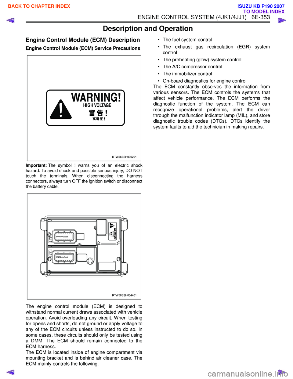
Important:The symbol ! warns you of an electric shock
hazard. To avoid shock and possible serious injury, DO NOT
touch the terminals. When disconnecting the harness
connectors, always turn OFF the ignition switch or disconnect
the battery cable.
The engine control module (ECM) is designed to
withstand normal current draws associated with vehicle
operation. Avoid overloading any circuit. When testing
for opens and shorts, do not ground or apply voltage to
any of the ECM circuits unless instructed to do so. In
some cases, these circuits should only be tested using
a DMM. The ECM should remain connected to the
ECM harness.
The ECM is located inside of engine compartment via
mounting bracket and is behind air cleaner case. The
ECM mainly controls the following. • The fuel system control
• The exhaust gas recirculation (EGR) system control
• The preheating (glow) system control
• The A/C compressor control
• The immobilizer control
• On-board diagnostics for engine control
The ECM constantly observes the information from
various sensors. The ECM controls the systems that
affect vehicle performance. The ECM performs the
diagnostic function of the system. The ECM can
recognize operational problems, alert the driver
through the malfunction indicator lamp (MIL), and store
diagnostic trouble codes (DTCs). DTCs identify the
system faults to aid the technician in making repairs.
RTW56ESH000201
RTW56ESH004401
BACK TO CHAPTER INDEX
TO MODEL INDEX
ISUZU KB P190 2007
Page 1971 of 6020
6E-354 ENGINE CONTROL SYSTEM (4JK1/4JJ1)
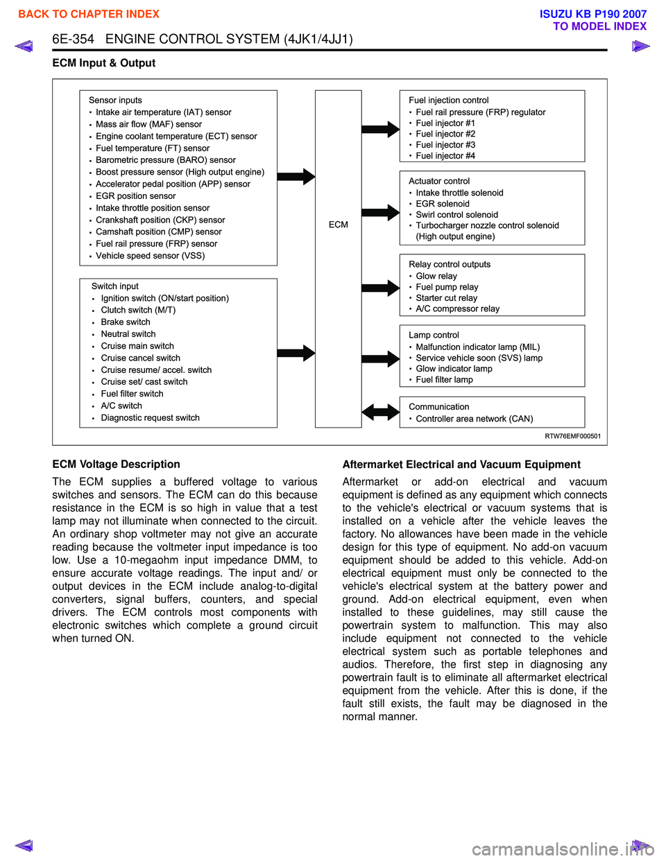
ECM Input & Output
ECM Voltage Description
The ECM supplies a buffered voltage to various
switches and sensors. The ECM can do this because
resistance in the ECM is so high in value that a test
lamp may not illuminate when connected to the circuit.
An ordinary shop voltmeter may not give an accurate
reading because the voltmeter input impedance is too
low. Use a 10-megaohm input impedance DMM, to
ensure accurate voltage readings. The input and/ or
output devices in the ECM include analog-to-digital
converters, signal buffers, counters, and special
drivers. The ECM controls most components with
electronic switches which complete a ground circuit
when turned ON. Aftermarket Electrical and Vacuum Equipment
Aftermarket or add-on electrical and vacuum
equipment is defined as any equipment which connects
to the vehicle's electrical or vacuum systems that is
installed on a vehicle after the vehicle leaves the
factory. No allowances have been made in the vehicle
design for this type of equipment. No add-on vacuum
equipment should be added to this vehicle. Add-on
electrical equipment must only be connected to the
vehicle's electrical system at the battery power and
ground. Add-on electrical equipment, even when
installed to these guidelines, may still cause the
powertrain system to malfunction. This may also
include equipment not connected to the vehicle
electrical system such as portable telephones and
audios. Therefore, the first step in diagnosing any
powertrain fault is to eliminate all aftermarket electrical
equipment from the vehicle. After this is done, if the
fault still exists, the fault may be diagnosed in the
normal manner.
RTW76EMF000501
Sensor inputs
· Intake air temperature (IAT) sensor
· Mass air flow (MAF) sensor
· Engine coolant temperature (ECT) sensor
· Fuel temperature (FT) sensor
· Barometric pressure (BARO) sensor
· Boost pressure sensor (High output engine)
· Accelerator pedal position (APP) sensor
· EGR position sensor
· Intake throttle position sensor
· Crankshaft position (CKP) sensor
· Camshaft position (CMP) sensor
· Fuel rail pressure (FRP) sensor
· Vehicle speed sensor (VSS)
Switch input
· Ignition switch (ON/start position)
· Clutch switch (M/T)
· Brake switch
· Neutral switch
· Cruise main switch
· Cruise cancel switch
· Cruise resume/ accel. switch
· Cruise set/ cast switch
· Fuel filter switch
· A/C switch
· Diagnostic request switch
Fuel injection control
· Fuel rail pressure (FRP) regulator
· Fuel injector #1
· Fuel injector #2
· Fuel injector #3
· Fuel injector #4
Relay control outputs
· Glow relay
· Fuel pump relay
· Starter cut relay
· A/C compressor relay
Lamp control
· Malfunction indicator lamp (MIL)
· Service vehicle soon (SVS) lamp
· Glow indicator lamp
· Fuel filter lamp
Communication
· Controller area network (CAN)
Actuator control
· Intake throttle solenoid
· EGR solenoid
· Swirl control solenoid
· Turbocharger nozzle control solenoid
(High output engine)ECM
BACK TO CHAPTER INDEX
TO MODEL INDEX
ISUZU KB P190 2007
Page 1972 of 6020
ENGINE CONTROL SYSTEM (4JK1/4JJ1) 6E-355
Electrostatic Discharge Damage
Electronic components used in the ECM are often
designed to carry very low voltage. Electronic
components are susceptible to damage caused by
electrostatic discharge. By comparison, as much as
4,000 volts may be needed for a person to feel even
the zap of a static discharge. There are several ways
for a person to become statically charged. The most
common methods of charging are by friction and
induction.
• An example of charging by friction is a person sliding across a vehicle seat.
Important: To prevent possible electrostatic discharge
damage, follow these guidelines:
• Do not touch the ECM connector pins or soldered components on the ECM circuit board.
• Do not open the replacement part package until the part is ready to be installed.
• Before removing the part from the package, ground the package to a known good ground on
the vehicle.
• If the part has been handled while sliding across the seat, while sitting down from a standing
position, or while walking a distance, touch a
known good ground before installing the part.
• Charge by induction occurs when a person with well insulated shoes stands near a highly charged
object and momentarily touches ground. Charges
of the same polarity are drained off leaving the
person highly charged with opposite polarity.
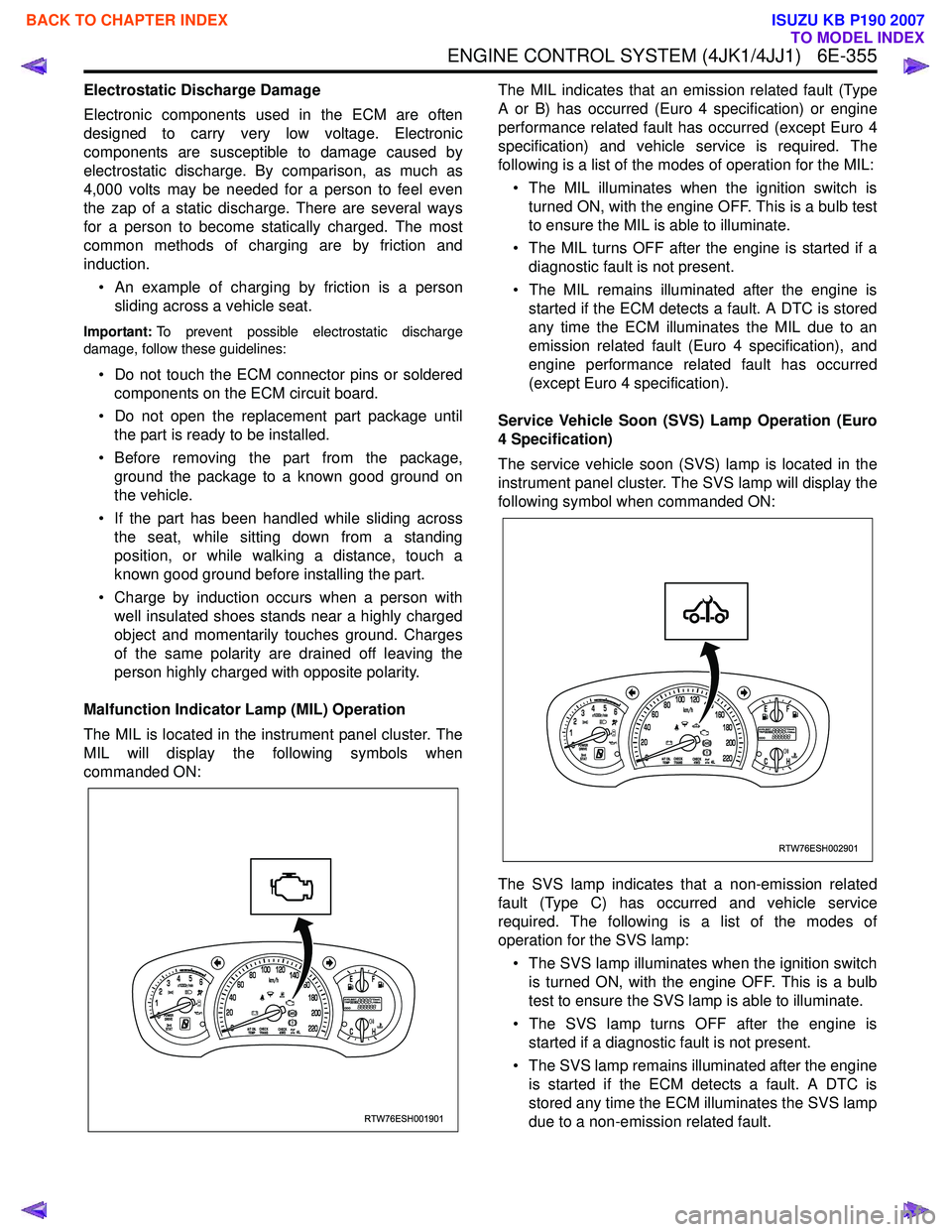
Malfunction Indicator Lamp (MIL) Operation
The MIL is located in the instrument panel cluster. The
MIL will display the following symbols when
commanded ON: The MIL indicates that an emission related fault (Type
A or B) has occurred (Euro 4 specification) or engine
performance related fault has occurred (except Euro 4
specification) and vehicle service is required. The
following is a list of the modes of operation for the MIL:
• The MIL illuminates when the ignition switch is turned ON, with the engine OFF. This is a bulb test
to ensure the MIL is able to illuminate.
• The MIL turns OFF after the engine is started if a diagnostic fault is not present.
• The MIL remains illuminated after the engine is started if the ECM detects a fault. A DTC is stored
any time the ECM illuminates the MIL due to an
emission related fault (Euro 4 specification), and
engine performance related fault has occurred
(except Euro 4 specification).
Service Vehicle Soon (SVS) Lamp Operation (Euro
4 Specification)
The service vehicle soon (SVS) lamp is located in the
instrument panel cluster. The SVS lamp will display the
following symbol when commanded ON:
The SVS lamp indicates that a non-emission related
fault (Type C) has occurred and vehicle service
required. The following is a list of the modes of
operation for the SVS lamp:
• The SVS lamp illuminates when the ignition switch is turned ON, with the engine OFF. This is a bulb
test to ensure the SVS lamp is able to illuminate.
• The SVS lamp turns OFF after the engine is started if a diagnostic fault is not present.
• The SVS lamp remains illuminated after the engine is started if the ECM detects a fault. A DTC is
stored any time the ECM illuminates the SVS lamp
due to a non-emission related fault.
RTW76ESH001901
RTW76ESH002901
BACK TO CHAPTER INDEX
TO MODEL INDEX
ISUZU KB P190 2007
Page 1999 of 6020
6H-2 ENGINE SPEED CONTROL SYSTEM (4JK1/4JJ1)
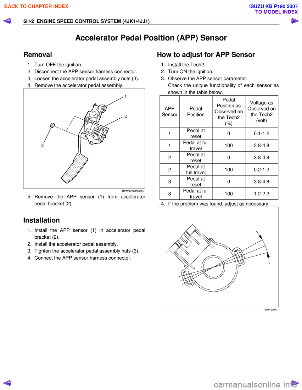
Accelerator Pedal Position (APP) Sensor
Removal
1. Turn OFF the ignition.
2. Disconnect the APP sensor harness connector.
3. Loosen the accelerator pedal assembly nuts (3).
4. Remove the accelerator pedal assembly.
RTW 56ESH000301
5. Remove the APP sensor (1) from accelerator
pedal bracket (2).
Installation
1. Install the APP sensor (1) in accelerator pedal
bracket (2).
2. Install the accelerator pedal assembly.
3. Tighten the accelerator pedal assembly nuts (3).
4. Connect the APP sensor harness connector.
How to adjust for APP Sensor
1. Install the Tech2.
2. Turn ON the ignition.
3. Observe the APP sensor parameter.
Check the unique functionality of each sensor as shown in the table below.
APP
Sensor Pedal
Position Pedal
Position as
Observed on the Tech2 (%) Voltage as
Observed on the Tech2 (volt)
1 Pedal at
reset 0 0.1-1.2
1 Pedal at full
travel 100 3.8-4.8
2 Pedal at
reset 0 3.8-4.8
2 Pedal at
full travel 100 0.2-1.2
3 Pedal at
reset 0 3.8-4.8
3 Pedal at full
travel 100 1.2-2.2
4. If the problem was found, adjust as necessary.
101RY00011
BACK TO CHAPTER INDEX
TO MODEL INDEX
ISUZU KB P190 2007
Page 2002 of 6020
6-2 ENGINE DIAGNOSIS (C24SE)
Engine Diagnosis
Hard Starting
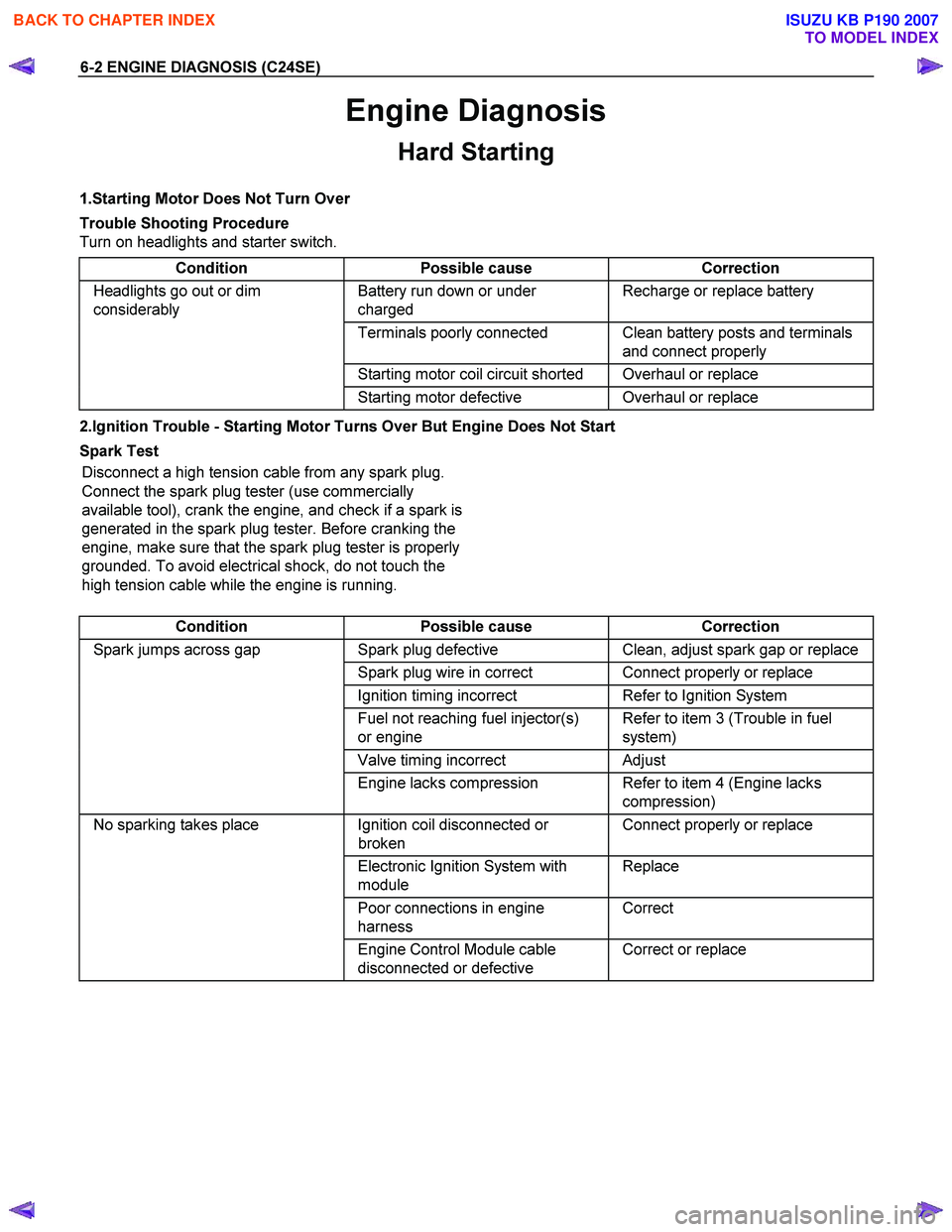
1.Starting Motor Does Not Turn Over
Trouble Shooting Procedure
Turn on headlights and starter switch.
Condition Possible cause Correction
Headlights go out or dim
considerably Battery run down or under
charged Recharge or replace battery
Terminals poorly connected Clean battery posts and terminals
and connect properly
Starting motor coil circuit shorted Overhaul or replace
Starting motor defective Overhaul or replace
2.Ignition Trouble - Starting Motor Turns Over But Engine Does Not Start
Spark Test Disconnect a high tension cable from any spark plug.
Connect the spark plug tester (use commercially
available tool), crank the engine, and check if a spark is
generated in the spark plug tester. Before cranking the
engine, make sure that the spark plug tester is properly
grounded. To avoid electrical shock, do not touch the
high tension cable while the engine is running.
Condition Possible cause Correction
Spark jumps across gap Spark plug defective Clean, adjust spark gap or replace
Spark plug wire in correct Connect properly or replace
Ignition timing incorrect Refer to Ignition System
Fuel not reaching fuel injector(s)
or engine Refer to item 3 (Trouble in fuel
system)
Valve timing incorrect Adjust
Engine lacks compression Refer to item 4 (Engine lacks
compression)
No sparking takes place Ignition coil disconnected or
broken Connect properly or replace
Electronic Ignition System with
module Replace
Poor connections in engine
harness Correct
Engine Control Module cable
disconnected or defective Correct or replace
BACK TO CHAPTER INDEX
TO MODEL INDEX
ISUZU KB P190 2007
Page 2003 of 6020
ENGINE DIAGNOSIS (C24SE) 6-3
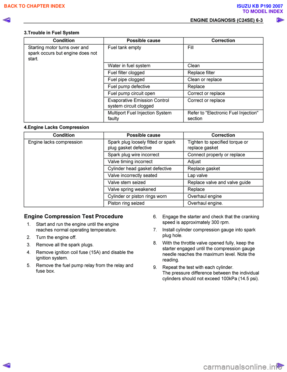
3.Trouble in Fuel System Condition Possible cause Correction
Starting motor turns over and
spark occurs but engine does not
start. Fuel tank empty Fill
Water in fuel system Clean
Fuel filter clogged Replace filter
Fuel pipe clogged Clean or replace
Fuel pump defective Replace
Fuel pump circuit open Correct or replace
Evaporative Emission Control
system circuit clogged Correct or replace
Multiport Fuel Injection System
faulty Refer to "Electronic Fuel Injection"
section
4.Engine Lacks Compression
Condition Possible cause Correction
Engine lacks compression Spark plug loosely fitted or spark
plug gasket defective Tighten to specified torque or
replace gasket
Spark plug wire incorrect Connect properly or replace
Valve timing incorrect Adjust
Cylinder head gasket defective Replace gasket
Valve incorrectly seated Lap valve
Valve stem seized Replace valve and valve guide
Valve spring weakened Replace
Cylinder or piston rings worn Overhaul engine
Piston ring seized Overhaul engine.
Engine Compression Test Procedure
1. Start and run the engine until the engine
reaches normal operating temperature.
2. Turn the engine off.
3. Remove all the spark plugs.
4. Remove ignition coil fuse (15A) and disable the ignition system.
5. Remove the fuel pump relay from the relay and fuse box. 6. Engage the starter and check that the cranking
speed is approximately 300 rpm.
7. Install cylinder compression gauge into spark plug hole.
8. With the throttle valve opened fully, keep the starter engaged until the compression gauge
needle reaches the maximum level. Note the
reading.
9. Repeat the test with each cylinder. The pressure difference between the individual
cylinders should not exceed 100kPa (14.5 psi).
BACK TO CHAPTER INDEX
TO MODEL INDEX
ISUZU KB P190 2007