Page 2025 of 6020
ENGINE MECHANICAL (C24SE) 6A-11
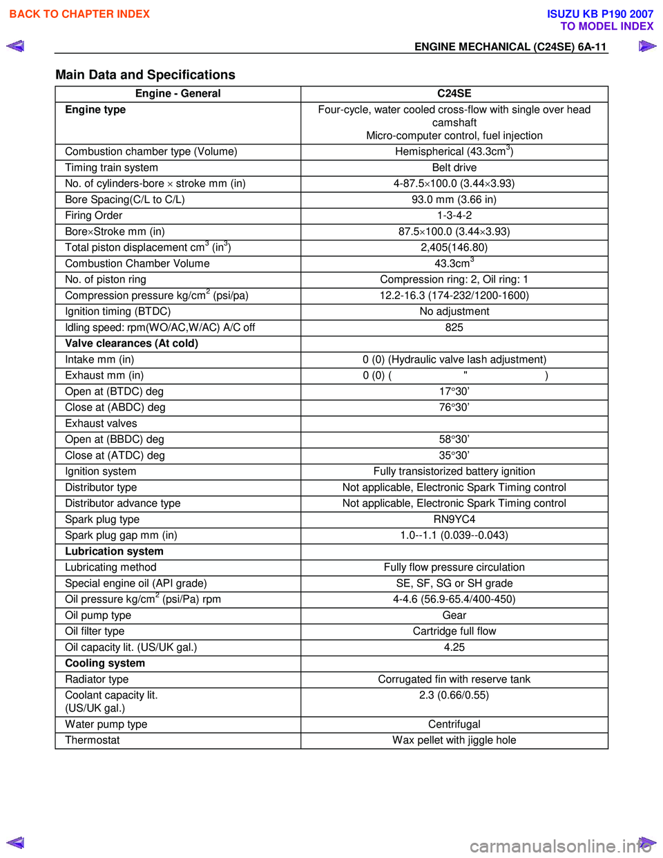
Main Data and Specifications
Engine - General C24SE
Engine type Four-cycle, water cooled cross-flow with single over head
camshaft
Micro-computer control, fuel injection
Combustion chamber type (Volume) Hemispherical (43.3cm3)
Timing train system Belt drive
No. of cylinders-bore × stroke mm (in) 4-87.5 ×100.0 (3.44 ×3.93)
Bore Spacing(C/L to C/L) 93.0 mm (3.66 in)
Firing Order 1-3-4-2
Bore×Stroke mm (in) 87.5 ×100.0 (3.44 ×3.93)
Total piston displacement cm3 (in3) 2,405(146.80)
Combustion Chamber Volume 43.3cm3
No. of piston ring Compression ring: 2, Oil ring: 1
Compression pressure kg/cm2 (psi/pa) 12.2-16.3 (174-232/1200-1600)
Ignition timing (BTDC) No adjustment
Idling speed: rpm(W O/AC,W /AC) A/C off 825
Valve clearances (At cold)
Intake mm (in) 0 (0) (Hydraulic valve lash adjustment)
Exhaust mm (in) 0 (0) ( " )
Open at (BTDC) deg 17°30’
Close at (ABDC) deg 76°30’
Exhaust valves
Open at (BBDC) deg 58°30’
Close at (ATDC) deg 35°30’
Ignition system Fully transistorized battery ignition
Distributor type Not applicable, Electronic Spark Timing control
Distributor advance type Not applicable, Electronic Spark Timing control
Spark plug type RN9YC4
Spark plug gap mm (in) 1.0--1.1 (0.039--0.043)
Lubrication system
Lubricating method Fully flow pressure circulation
Special engine oil (API grade) SE, SF, SG or SH grade
Oil pressure kg/cm2 (psi/Pa) rpm 4-4.6 (56.9-65.4/400-450)
Oil pump type Gear
Oil filter type Cartridge full flow
Oil capacity lit. (US/UK gal.) 4.25
Cooling system
Radiator type Corrugated fin with reserve tank
Coolant capacity lit.
(US/UK gal.) 2.3 (0.66/0.55)
W ater pump type
Centrifugal
Thermostat W ax pellet with jiggle hole
BACK TO CHAPTER INDEX
TO MODEL INDEX
ISUZU KB P190 2007
Page 2026 of 6020
6A-12 ENGINE MECHANICAL (C24SE)
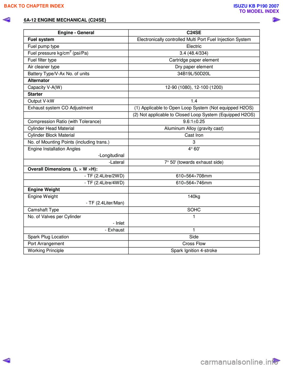
Engine - General C24SE
Fuel system Electronically controlled Multi Port Fuel Injection System
Fuel pump type Electric
Fuel pressure kg/cm2 (psi/Pa) 3.4 (48.4/334)
Fuel filter type Cartridge paper element
Air cleaner type Dry paper element
Battery Type/V-Ax No. of units 34B19L/50D20L
Alternator
Capacity V-A(W ) 12-90 (1080), 12-100 (1200)
Starter
Output V-kW 1.4
Exhaust system CO Adjustment (1) Applicable to Open Loop System (Not equipped H2OS)
(2) Not applicable to Closed Loop System (Equipped H2OS)
Compression Ratio (with Tolerance) 9.6:1±0.25
Cylinder Head Material Aluminum Alloy (gravity cast)
Cylinder Block Material Cast Iron
No. of Mounting Points (including trans.) 3
Engine Installation Angles
-Longitudinal 4
° 60'
-Lateral 7° 50' (towards exhaust side)
Overall Dimensions (L ×
××
×
W ×
××
×
H):
- TF (2.4Litre/2W D)610×564 ×708mm
- TF (2.4Litre/4W D) 610×564 ×746mm
Engine Weight
Engine W eight
- TF (2.4Liter/Man) 140kg
Camshaft Type
SOHC
No. of Valves per Cylinder
- Inlet1
- Exhaust
1
Spark Plug Location Side
Port Arrangement Cross Flow
W orking Principle Spark Ignition 4-stroke
BACK TO CHAPTER INDEX
TO MODEL INDEX
ISUZU KB P190 2007
Page 2027 of 6020

ENGINE MECHANICAL (C24SE) 6A-13
Valve System C24SE
Actuation Type Direct-acting Inverted Bucked Tappet
Valve Clearance Adjustment Hydraulic
Valve Rotor Type None
Inlet-Valve Material Chromium Alloyed Steel
-Seat Insert MaterialSintered Iron
Exhaust-Valve Material Head: Cr-Mn-Ni Alloyed Shaft: Cr-Si Alloyed &Cr plated
-Seat Insert MaterialSintered Iron
Valve Spring Material GME 06 100-C1
Valve Guide Material QS 13 MR 00
Valve Seal Type Lip
Water Pump C24SE
Type Centrifugal
Drive-Material &Type HNBR Toothed-belt
Bearing Type Double Row Ball
Shaft Seal Type Mechanical Ceramic
Thermostat-Coolant C24SE
Type Bypass
Oil Pump & Filter C24SE
Type Gear Pump
Location Front of Engine
Drive Direct Crankshaft Driven
Filter Type Full Flow with Bypass for blocked filter
Oil & Oil Reservoir C24SE
Reservoir-Description & Location 1-piece below Engine
Reservoir Material Aluminum Alloy (pressure cast)
Replacement Oil Fill Volume
-W ith Filter change4.25liters
-W ithout Filter change 4.00liters
Recommended Oil-Run-in 10W /30SG
-Service (above-18°C) 10W /40SG
-Service (below-18°C) 5W /30SG
Oil Classification API&CCMC
Ignition Components C24SE
Spark Plugs Conventional
Type Electronic Spark Control
No. of Coils &Type 2 Solid State
Coil Location Engine-mounted
Ignition Lead Type Inductive (hi-resistance)
BACK TO CHAPTER INDEX
TO MODEL INDEX
ISUZU KB P190 2007
Page 2078 of 6020
6A-64 ENGINE MECHANICAL (C24SE)
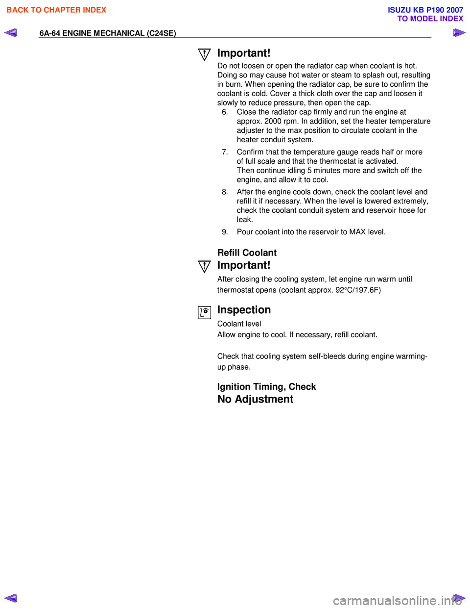
Important!
Do not loosen or open the radiator cap when coolant is hot.
Doing so may cause hot water or steam to splash out, resulting
in burn. W hen opening the radiator cap, be sure to confirm the
coolant is cold. Cover a thick cloth over the cap and loosen it
slowly to reduce pressure, then open the cap.
6. Close the radiator cap firmly and run the engine at approx. 2000 rpm. In addition, set the heater temperature
adjuster to the max position to circulate coolant in the
heater conduit system.
7. Confirm that the temperature gauge reads half or more of full scale and that the thermostat is activated.
Then continue idling 5 minutes more and switch off the
engine, and allow it to cool.
8. After the engine cools down, check the coolant level and refill it if necessary. W hen the level is lowered extremely,
check the coolant conduit system and reservoir hose for
leak.
9. Pour coolant into the reservoir to MAX level.
Refill Coolant
Important!
After closing the cooling system, let engine run warm until
thermostat opens (coolant approx. 92 °C/197.6F)
Inspection
Coolant level
Allow engine to cool. If necessary, refill coolant.
Check that cooling system self-bleeds during engine warming-
up phase.
Ignition Timing, Check
No Adjustment
BACK TO CHAPTER INDEX
TO MODEL INDEX
ISUZU KB P190 2007
Page 2085 of 6020
ENGINE MECHANICAL (C24SE) 6A-71
Installation
(2.4L)
1. Install the ECM to the ECM bracket on engine.
2. Tighten the four screws to the bracket.
3. Connect the connector.
ECT
Removal
1. Remove wiring harness plug and coolant temperature sensor.
Tighten (Torque)
Temperature sensor to intake pipe - 10 N ⋅m (1.0 kgf ⋅m)
W iring harness plug to temperature sensor
Inspection
Coolant level
Idle Air Control (IAC) Valve
Removal
1. Remove wiring harness plug, hose clamps and idle speed adjuster.
Installation
1. Install idle speed adjuster, hose clamps and wiring harness plug.
Ignition Coil
Removal
1. Remove 2 bolts, plug and ignition coil.
Installation
1. Install ignition coil, plug and bolts.
BACK TO CHAPTER INDEX
TO MODEL INDEX
ISUZU KB P190 2007
Page 2092 of 6020
6A-78 ENGINE MECHANICAL (C24SE)
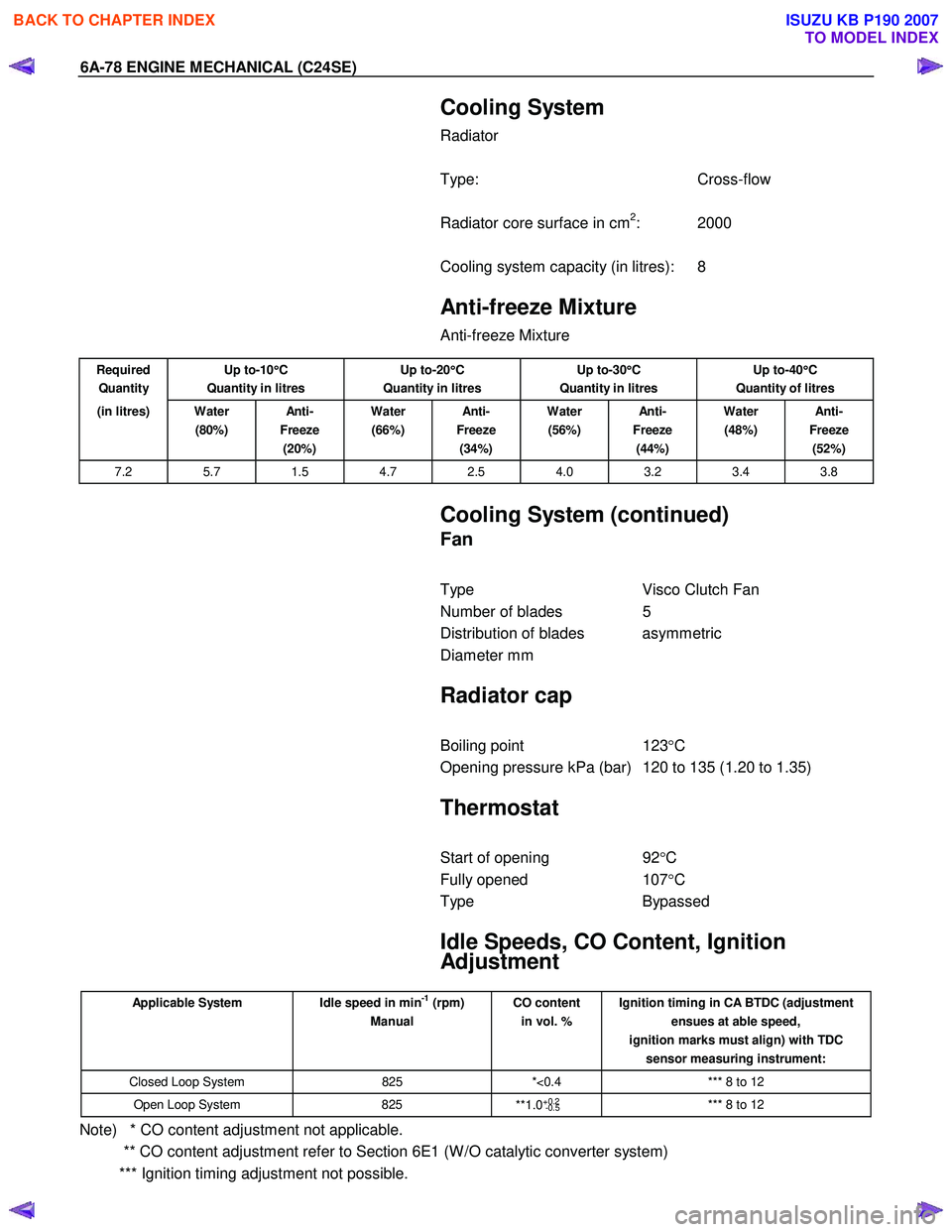
Cooling System
Radiator
Type: Cross-flow
Radiator core surface in cm
2: 2000
Cooling system capacity (in litres): 8
Anti-freeze Mixture
Anti-freeze Mixture
Required
Quantity Up to-10
°
°°
°
C
Quantity in litres Up to-20
°
°°
°
C
Quantity in litres Up to-30
°
°°
°
C
Quantity in litres Up to-40
°
°°
°
C
Quantity of litres
(in litres) Water (80%) An ti -
Freeze (20%) Water
(66%) An ti -
Freeze (34%) Water
(56%) An ti -
Freeze (44%) Water
(48%) An ti -
Freeze (52%)
7.2 5.7 1.5 4.7 2.5 4.0 3.2 3.4 3.8
Cooling System (continued)
Fan
Type Visco Clutch Fan
Number of blades 5
Distribution of blades asymmetric
Diameter mm
Radiator cap
Boiling point 123°C
Opening pressure kPa (bar) 120 to 135 (1.20 to 1.35)
Thermostat
Start of opening 92°C
Fully opened 107°C
Type Bypassed
Idle Speeds, CO Content, Ignition
Adjustment
Applicable System Idle speed in min-1 (rpm)
Manual CO content
in vol. % Ignition timing in CA BTDC (adjustment
ensues at able speed,
ignition marks must align) with TDC sensor measuring instrument:
Closed Loop System 825 *<0.4 *** 8 to 12
Open Loop System 825
**1.0+0.2
-0.5 *** 8 to 12
Note) * CO content adjustment not applicable.
** CO content adjustment refer to Section 6E1 (W /O catalytic converter system)
*** Ignition timing adjustment not possible.
BACK TO CHAPTER INDEX
TO MODEL INDEX
ISUZU KB P190 2007
Page 2129 of 6020
ENGINE FUEL (C24SE) 6C-11
140R100028
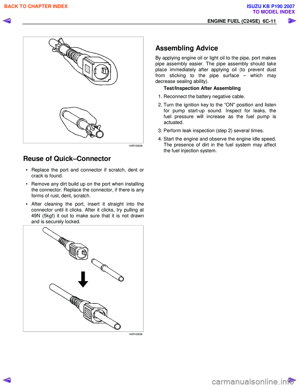
Reuse of Quick–Connector
• Replace the port and connector if scratch, dent or
crack is found.
• Remove any dirt build up on the port when installing the connector. Replace the connector, if there is an
y
forms of rust, dent, scratch.
•
After cleaning the port, insert it straight into the
connector until it clicks. After it clicks, try pulling at
49N (5kgf) it out to make sure that it is not drawn
and is securely locked.
140R100036
Assembling Advice
By applying engine oil or light oil to the pipe, port makes
pipe assembly easier. The pipe assembly should take
place immediately after applying oil (to prevent dust
from sticking to the pipe surface – which ma
y
decrease sealing ability).
Test/Inspection After Assembling
1. Reconnect the battery negative cable.
2. Turn the ignition key to the “ON" position and listen
for pump start-up sound. Inspect for leaks, the
fuel pressure will increase as the fuel pump is
actuated.
3. Perform leak inspection (step 2) several times.
4. Start the engine and observe the engine idle speed.
The presence of dirt in the fuel system may affect
the fuel injection system.
BACK TO CHAPTER INDEX
TO MODEL INDEX
ISUZU KB P190 2007
Page 2130 of 6020
6C-12 ENGINE FUEL (C24SE)
Fuel Pump Relay
General Description
In order to control the fuel pump and sender assembly
(FPAS) operation, the FPAS relay is provided. W hen
the starter switch is turned to “ON" position, the FPAS
relay operates the FPAS for 2 seconds.
W hen it is turned to “START" position, the Engine
Control Module receives the reference pulse from the
Ignition Control Module and it operates the relay, again
causing the FPAS to feed fuel.
BACK TO CHAPTER INDEX
TO MODEL INDEX
ISUZU KB P190 2007