2007 ISUZU KB P190 height
[x] Cancel search: heightPage 3126 of 6020
Engine Mechanical – V6 Page 6A1–349
Page 6A1–349
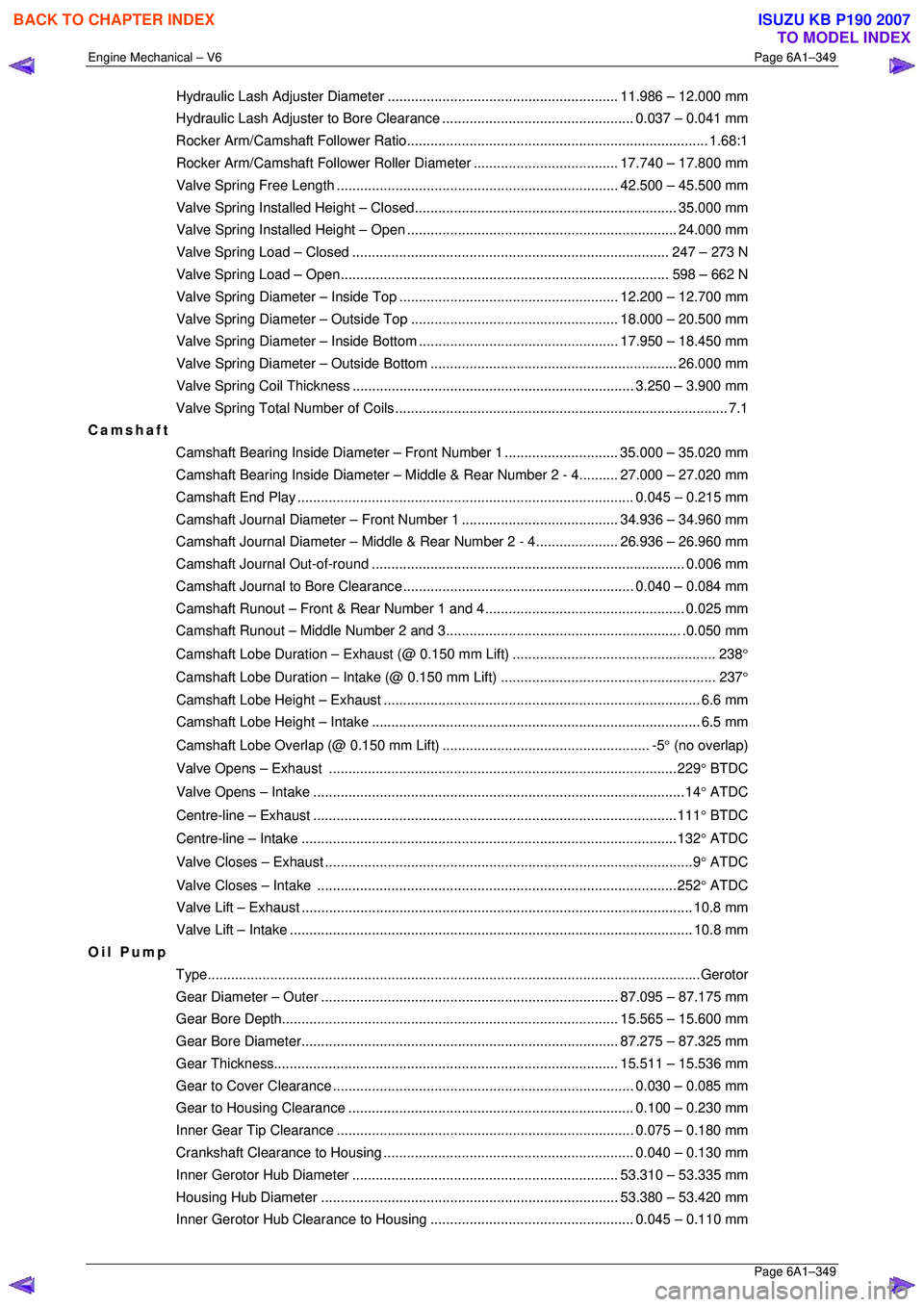
Hydraulic Lash Adjuster Diameter ........................................................... 11.986 – 12.000 mm
Hydraulic Lash Adjuster to Bore Clearance................................................. 0. 037 – 0.041 mm
Rocker Arm/Camshaft Fo llower Ratio............................................................................. 1. 68:1
Rocker Arm/Camshaft Follower Ro ller Diameter..................................... 17. 740 – 17.800 mm
Valve Spring Free Le ngth ........................................................................ 42.500 – 45.500 mm
Valve Spring Installed He ight – Closed................................................................... 35. 000 mm
Valve Spring Installed Height – Open ..................................................................... 24.000 mm
Valve Spring Load – Closed................................................................................. 247 – 273 N
Valve Spring Load – Open.................................................................................... 598 – 662 N
Valve Spring Diameter – In side Top ........................................................ 12.200 – 12.700 mm
Valve Spring Diameter – Ou tside Top ..................................................... 18.000 – 20.500 mm
Valve Spring Diameter – In side Bottom ................................................... 17.950 – 18.450 mm
Valve Spring Diameter – Outside Bottom ............................................................... 26. 000 mm
Valve Spring Coil Thi ckness ........................................................................ 3.250 – 3.900 mm
Valve Spring Total Nu mber of Coils..................................................................................... 7.1
Camshaft
Camshaft Bearing Inside Diameter – Front Number 1 ............................. 35. 000 – 35.020 mm
Camshaft Bearing Inside Diam eter – Middle & Rear Number 2 - 4..........27.000 – 27.020 mm
Camshaft End Play ...................................................................................... 0. 045 – 0.215 mm
Camshaft Journal Diameter – Fr ont Number 1........................................ 34. 936 – 34.960 mm
Camshaft Journal Diameter – Middle & Rear Number 2 - 4..................... 26. 936 – 26.960 mm
Camshaft Journal Ou t-of-round................................................................................ 0. 006 mm
Camshaft Journal to Bore Clearance ........................................................... 0.040 – 0.084 mm
Camshaft Runout – Front & R ear Number 1 and 4................................................... 0. 025 mm
Camshaft Runout – Middle Number 2 and 3............................................................ .0 .050 mm
Camshaft Lobe Duration – Ex haust (@ 0.150 mm Lift) .................................................... 238 °
Camshaft Lobe Duration – In take (@ 0.150 mm Lift) ....................................................... 237 °
Camshaft Lobe Height – Exhaust ................................................................................. 6.6 mm
Camshaft Lobe Height – Intake.................................................................................... 6.5 mm
Camshaft Lobe Overlap (@ 0.150 mm Lift) ..................................................... -5 ° (no overlap)
Valve Opens – Exhaust .........................................................................................229 ° BTDC
Valve Opens – Intake ...............................................................................................14 ° ATDC
Centre-line – Exhaust .............................................................................................111 ° BTDC
Centre-line – Intake ................................................................................................132 ° ATDC
Valve Closes – Exhaust ..............................................................................................9 ° ATDC
Valve Closes – Intake ............................................................................................252 ° ATDC
Valve Lift – Ex haust .................................................................................................... 10.8 mm
Valve Lift – Intake....................................................................................................... 10. 8 mm
Oil Pump
Type........................................................................................................................... ...Gerotor
Gear Diameter – Ou ter ............................................................................ 87.095 – 87.175 mm
Gear Bore Dept h...................................................................................... 15. 565 – 15.600 mm
Gear Bore Diamet er................................................................................. 87.275 – 87.325 mm
Gear Thickness ........................................................................................ 15. 511 – 15.536 mm
Gear to Cover Clear ance ............................................................................. 0.030 – 0.085 mm
Gear to Housing Cle arance......................................................................... 0. 100 – 0.230 mm
Inner Gear Tip Clear ance ............................................................................ 0.075 – 0.180 mm
Crankshaft Clearance to Housing................................................................ 0. 040 – 0.130 mm
Inner Gerotor Hub Di ameter.................................................................... 53. 310 – 53.335 mm
Housing Hub Diamet er ............................................................................ 53.380 – 53.420 mm
Inner Gerotor Hub Clearance to Housing .................................................... 0. 045 – 0.110 mm
BACK TO CHAPTER INDEX
TO MODEL INDEX
ISUZU KB P190 2007
Page 3199 of 6020
Engine Cooling – V6 Engine Page 6B1–64
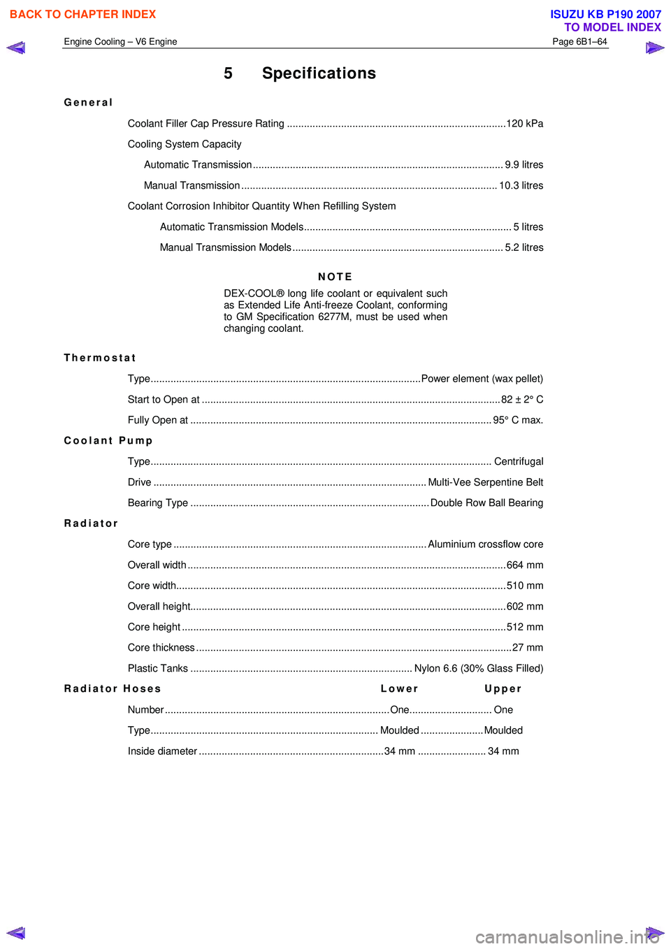
5 Specifications
General
Coolant Filler Cap Pressure Rating .............................................................................120 kPa
Cooling System Capacity
Automatic Transmission ........................................................................................ 9.9 litres
Manual Transmission .......................................................................................... 10.3 litres
Coolant Corrosion Inhibitor Quantity W hen Refilling System Automatic Transmission Models......................................................................... 5 litres
Manual Transmission Models .......................................................................... 5.2 litres
NOTE
DEX-COOL® long life coolant or equivalent such
as Extended Life Anti-freeze Coolant, conforming
to GM Specification 6277M, must be used when
changing coolant.
Thermostat Type...............................................................................................Power element (wax pellet)
Start to Open at ......................................................................................................... 82 ± 2 ° C
Fully Open at .......................................................................................................... 95° C ma x.
Coolant Pump
Type........................................................................................................................ Cen trifugal
Drive ................................................................................................ Multi-Vee Serpentine Belt
Bearing Type .................................................................................... Double Row Ball Bearing
Radiator
Core type ......................................................................................... Aluminium crossflow core
Overall width ................................................................................................................ 66 4 mm
Core width.................................................................................................................... 5 10 mm
Overall height............................................................................................................... 60 2 mm
Core height .................................................................................................................. 51 2 mm
Core thickness ............................................................................................................... 27 mm
Plastic Tanks .............................................................................. Nylon 6.6 (30% Glass Filled)
Radiator Hoses Lower Upper
Number ............................................................................... One............................. One
Type................................................................................ Moulded ...................... Moulded
Inside diameter ................................................................. 34 mm ........................ 34 mm
BACK TO CHAPTER INDEX
TO MODEL INDEX
ISUZU KB P190 2007
Page 3224 of 6020
Fuel System – V6 Page 6C – 22
Reinstall
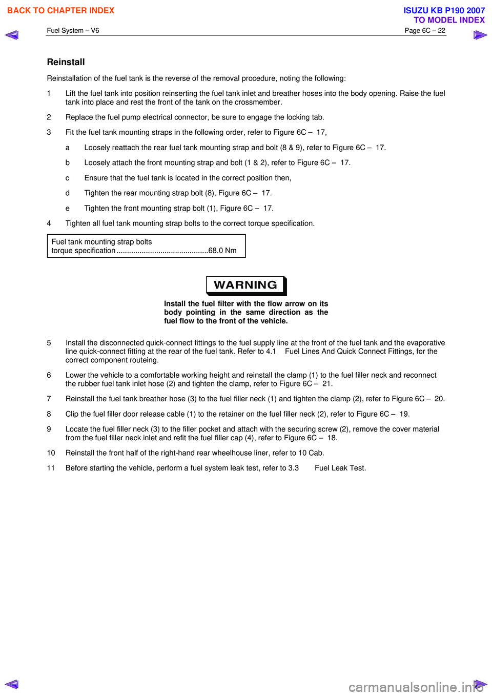
Reinstallation of the fuel tank is the reverse of the removal procedure, noting the following:
1 Lift the fuel tank into position reinserting the fuel tank inlet and breather hoses into the body opening. Raise the fuel tank into place and rest the front of the tank on the crossmember.
2 Replace the fuel pump electrical connector, be sure to engage the locking tab.
3 Fit the fuel tank mounting straps in the following order, refer to Figure 6C – 17, a Loosely reattach the rear fuel tank mounting strap and bolt (8 & 9), refer to Figure 6C – 17.
b Loosely attach the front mounting strap and bolt (1 & 2), refer to Figure 6C – 17.
c Ensure that the fuel tank is located in the correct position then,
d Tighten the rear mounting strap bolt (8), Figure 6C – 17.
e Tighten the front mounting strap bolt (1), Figure 6C – 17.
4 Tighten all fuel tank mounting strap bolts to the correct torque specification.
Fuel tank mounting strap bolts
torque specification ............................................68.0 Nm
Install the fuel filter with the flow arrow on its
body pointing in the same direction as the
fuel flow to the front of the vehicle.
5 Install the disconnected quick-connect fittings to the fuel supply line at the front of the fuel tank and the evaporative line quick-connect fitting at the rear of the fuel tank. Refer to 4.1 Fuel Lines And Quick Connect Fittings, for the
correct component routeing.
6 Lower the vehicle to a comfortable working height and reinstall the clamp (1) to the fuel filler neck and reconnect the rubber fuel tank inlet hose (2) and tighten the clamp, refer to Figure 6C – 21.
7 Reinstall the fuel tank breather hose (3) to the fuel filler neck (1) and tighten the clamp (2), refer to Figure 6C – 20.
8 Clip the fuel filler door release cable (1) to the retainer on the fuel filler neck (2), refer to Figure 6C – 19.
9 Locate the fuel filler neck (3) to the filler pocket and attach with the securing screw (2), remove the cover material from the fuel filler neck inlet and refit the fuel filler cap (4), refer to Figure 6C – 18.
10 Reinstall the front half of the right-hand rear wheelhouse liner, refer to 10 Cab.
11 Before starting the vehicle, perform a fuel system leak test, refer to 3.3 Fuel Leak Test.
BACK TO CHAPTER INDEX
TO MODEL INDEX
ISUZU KB P190 2007
Page 3734 of 6020
Powertrain Interface Module – V6 Page 6E1–73
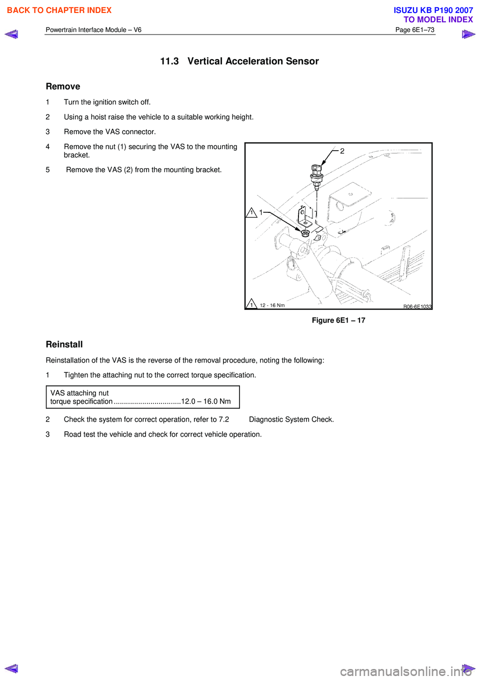
11.3 Vertical Acceleration Sensor
Remove
1 Turn the ignition switch off.
2 Using a hoist raise the vehicle to a suitable working height.
3 Remove the VAS connector.
4 Remove the nut (1) securing the VAS to the mounting bracket.
5 Remove the VAS (2) from the mounting bracket.
Figure 6E1 – 17
Reinstall
Reinstallation of the VAS is the reverse of the removal procedure, noting the following:
1 Tighten the attaching nut to the correct torque specification.
VAS attaching nut
torque specification .................................12.0 – 16.0 Nm
2 Check the system for correct operation, refer to 7.2 Diagnostic System Check.
3 Road test the vehicle and check for correct vehicle operation.
BACK TO CHAPTER INDEX
TO MODEL INDEX
ISUZU KB P190 2007
Page 4146 of 6020
UNIT REPAIR (AW30–40LE) 7A4–11
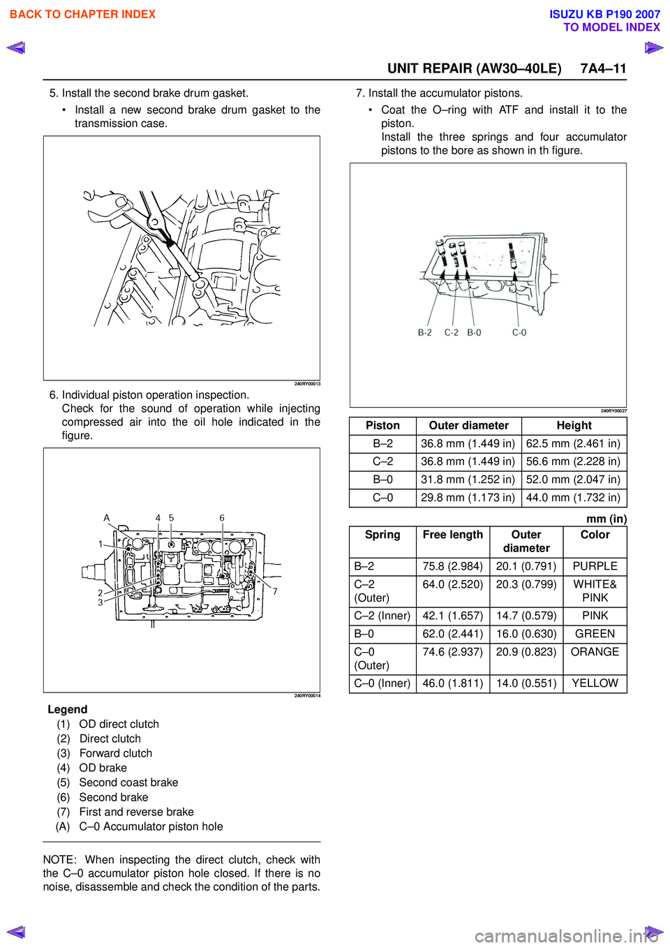
5. Install the second brake drum gasket. Install a new second brake drum gasket to the
transmission case.
240RY00013
6. Individual piston operation inspection. Check for the sound of operation while injecting
compressed air into the oil hole indicated in the
figure.
240RY00014
E ndOFCallout
NOTE: When inspecting the direct clutch, check with
the C –0 accumulator piston hole closed. If there is no
noise, disassemble and check the condition of the parts. 7. Install the accumulator pistons.
Coat the O –ring with ATF and install it to the
piston.
Install the three springs and four accumulator
pistons to the bore as shown in th figure.
240RY00027
mm (in)
Legend (1) OD direct clutch
(2) Direct clutch
(3) Forward clutch
(4) OD brake
(5) Second coast brake
(6) Second brake
(7) First and reverse brake
(A) C –0 Accumulator piston hole
Piston Outer diameter Height
B –2 36.8 mm (1.449 in) 62.5 mm (2.461 in)
C –2 36.8 mm (1.449 in) 56.6 mm (2.228 in)
B –0 31.8 mm (1.252 in) 52.0 mm (2.047 in)
C –0 29.8 mm (1.173 in) 44.0 mm (1.732 in)
Spring Free length Outer diameterColor
B –2 75.8 (2.984) 20.1 (0.791) PURPLE
C –2
(Outer) 64.0 (2.520) 20.3 (0.799) WHITE&
PINK
C –2 (Inner) 42.1 (1.657) 14.7 (0.579) PINK
B –0 62.0 (2.441) 16.0 (0.630) GREEN
C –0
(Outer) 74.6 (2.937) 20.9 (0.823) ORANGE
C –0 (Inner) 46.0 (1.811) 14.0 (0.551) YELLOW
BACK TO CHAPTER INDEX
TO MODEL INDEX
ISUZU KB P190 2007
Page 4164 of 6020
UNIT REPAIR (AW30–40LE) 7A4–29
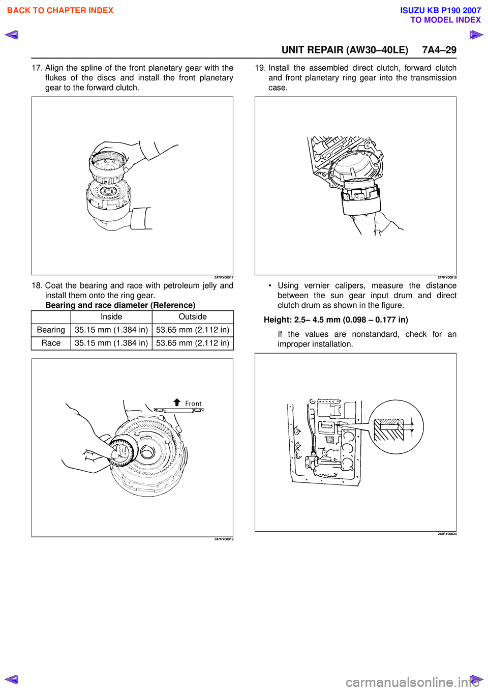
17. Align the spline of the front planetary gear with theflukes of the discs and install the front planetary
gear to the forward clutch.
247RY00017
18. Coat the bearing and race with petroleum jelly and install them onto the ring gear.
Bearing and race diameter (Reference)
247RY00019
19. Install the assembled direct clutch, forward clutch and front planetary ring gear into the transmission
case.
247RY00018
Using vernier calipers, measure the distance
between the sun gear input drum and direct
clutch drum as shown in the figure.
Height: 2.5 – 4.5 mm (0.098 – 0.177 in)
If the values are nonstandard, check for an
improper installation.
248RY00024
Inside Outside
Bearing 35.15 mm (1.384 in) 53.65 mm (2.112 in) Race 35.15 mm (1.384 in) 53.65 mm (2.112 in)
BACK TO CHAPTER INDEX
TO MODEL INDEX
ISUZU KB P190 2007
Page 4589 of 6020
MSG MODEL 7B-25
INSPECTION AND REPAIR
Make the necessary adjustments, repairs, and part replacements if excessive wear or damage is discovered during
inspection.
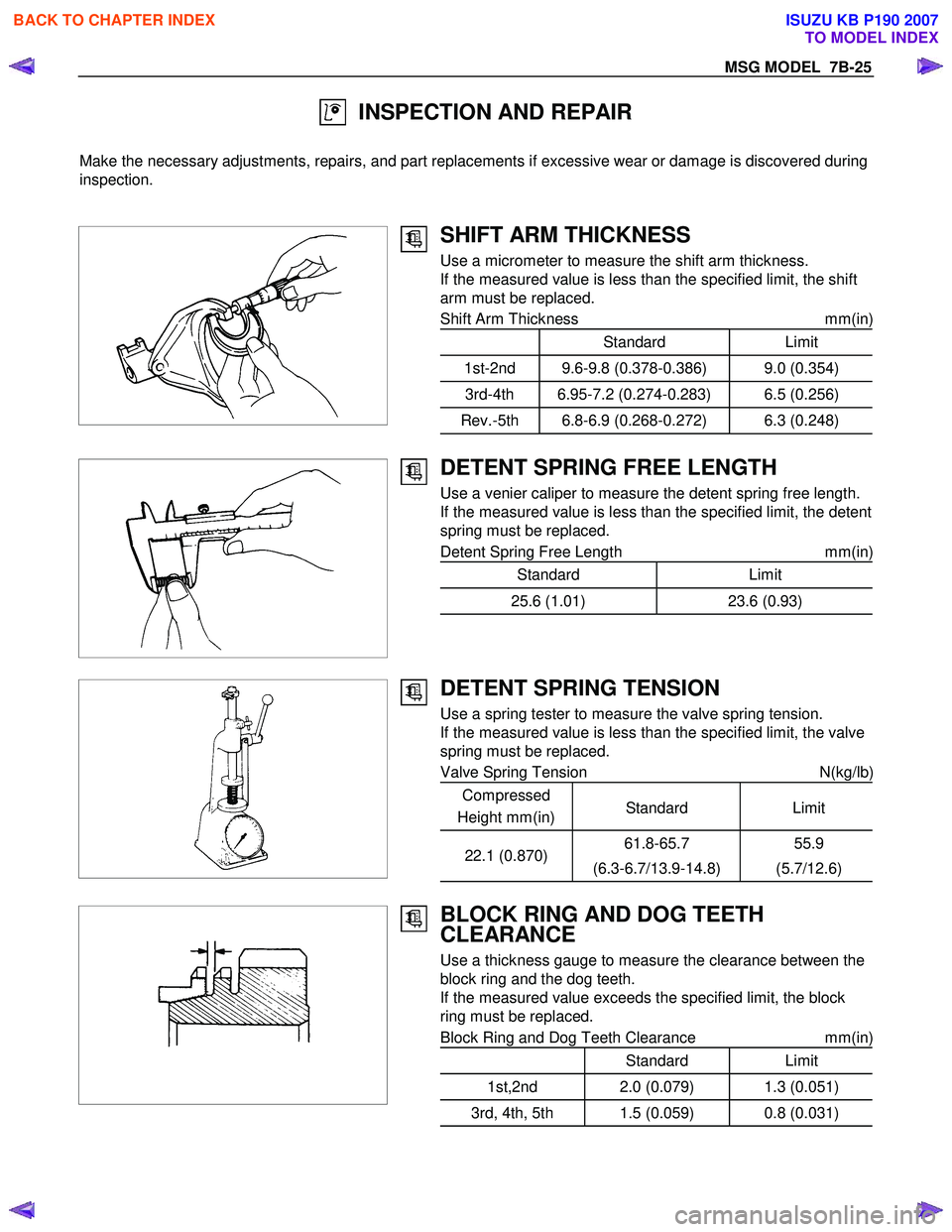
SHIFT ARM THICKNESS
Use a micrometer to measure the shift arm thickness.
If the measured value is less than the specified limit, the shift
arm must be replaced.
Shift Arm Thickness mm(in)
Standard Limit
1st-2nd 9.6-9.8 (0.378-0.386) 9.0 (0.354)
3rd-4th 6.95-7.2 (0.274-0.283) 6.5 (0.256)
Rev.-5th 6.8-6.9 (0.268-0.272) 6.3 (0.248)
DETENT SPRING FREE LENGTH
Use a venier caliper to measure the detent spring free length.
If the measured value is less than the specified limit, the detent
spring must be replaced.
Detent Spring Free Length mm(in)
Standard Limit
25.6 (1.01)23.6 (0.93)
DETENT SPRING TENSION
Use a spring tester to measure the valve spring tension.
If the measured value is less than the specified limit, the valve
spring must be replaced.
Valve Spring Tension N(kg/lb)
Compressed
Height mm(in) Standard
Limit
22.1 (0.870)61.8-65.7
(6.3-6.7/13.9-14.8) 55.9
(5.7/12.6)
BLOCK RING AND DOG TEETH
CLEARANCE
Use a thickness gauge to measure the clearance between the
block ring and the dog teeth.
If the measured value exceeds the specified limit, the block
ring must be replaced.
Block Ring and Dog Teeth Clearance mm(in)
Standard Limit
1st,2nd 2.0 (0.079) 1.3 (0.051)
3rd, 4th, 5th 1.5 (0.059) 0.8 (0.031)
BACK TO CHAPTER INDEX
TO MODEL INDEX
ISUZU KB P190 2007
Page 4628 of 6020
7B1-22 MANUAL TRANSMISSION
Inspection and Repair
Make the necessary adjustments and part replacements
if excessive wear or damage is discovered during
inspection.
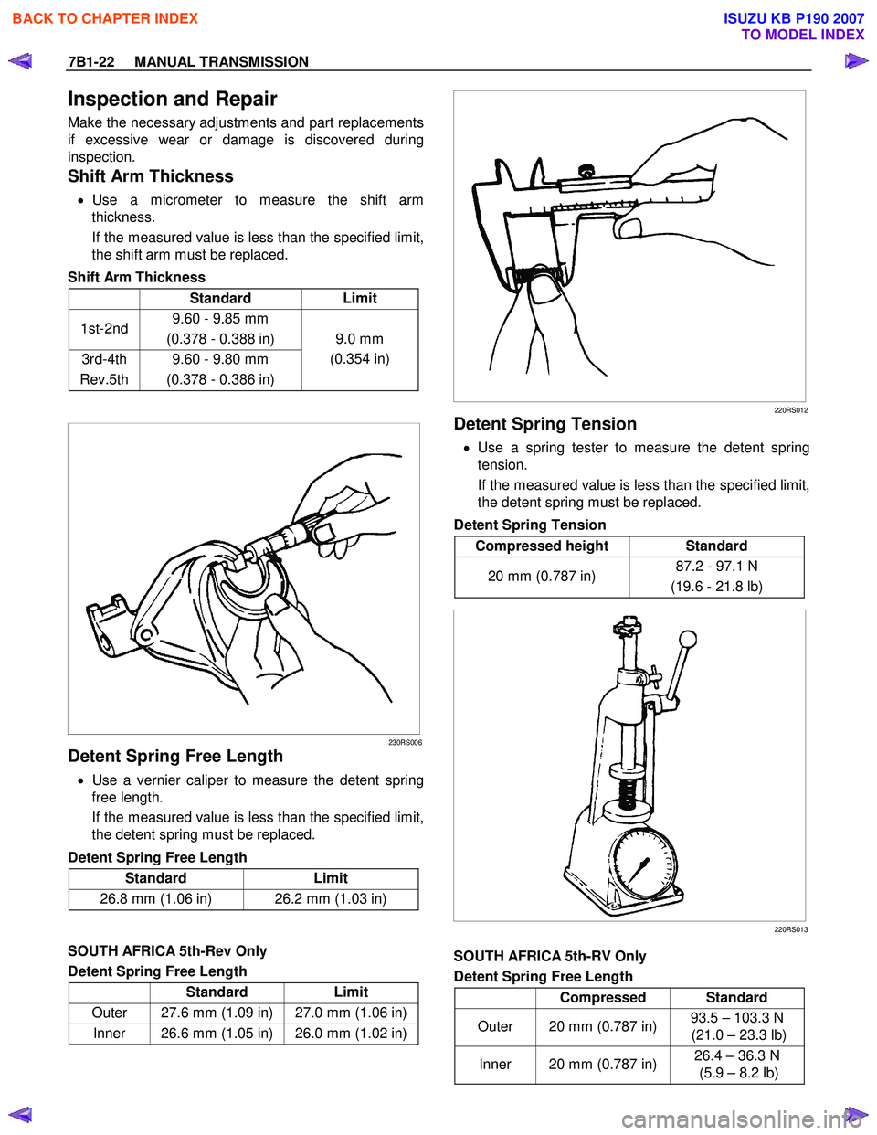
Shift Arm Thickness
• Use a micrometer to measure the shift arm
thickness.
If the measured value is less than the specified limit,
the shift arm must be replaced.
Shift Arm Thickness
Standard Limit
1st-2nd 9.60 - 9.85 mm
(0.378 - 0.388 in)
3rd-4th
Rev.5th 9.60 - 9.80 mm
(0.378 - 0.386 in) 9.0 mm
(0.354 in)
230RS006
Detent Spring Free Length
• Use a vernier caliper to measure the detent spring
free length.
If the measured value is less than the specified limit,
the detent spring must be replaced.
Detent Spring Free Length
Standard Limit
26.8 mm (1.06 in) 26.2 mm (1.03 in)
SOUTH AFRICA 5th-Rev Only
Detent Spring Free Length
Standard Limit
Outer 27.6 mm (1.09 in) 27.0 mm (1.06 in)
Inner 26.6 mm (1.05 in) 26.0 mm (1.02 in)
220RS012
Detent Spring Tension
• Use a spring tester to measure the detent spring
tension.
If the measured value is less than the specified limit,
the detent spring must be replaced.
Detent Spring Tension
Compressed height Standard
20 mm (0.787 in) 87.2 - 97.1 N
(19.6 - 21.8 lb)
220RS013
SOUTH AFRICA 5th-RV Only
Detent Spring Free Length
Compressed Standard
Outer 20 mm (0.787 in) 93.5 – 103.3 N
(21.0 – 23.3 lb)
Inner 20 mm (0.787 in) 26.4 – 36.3 N
(5.9 – 8.2 lb)
BACK TO CHAPTER INDEX
TO MODEL INDEX
ISUZU KB P190 2007