2007 ISUZU KB P190 height
[x] Cancel search: heightPage 4683 of 6020
MANUAL TRANSMISSION 7B1-77
Inspection and Repair
Make the necessary adjustments and part replacements
if excessive wear or damage is discovered during
inspection.
Shift Arm Thickness
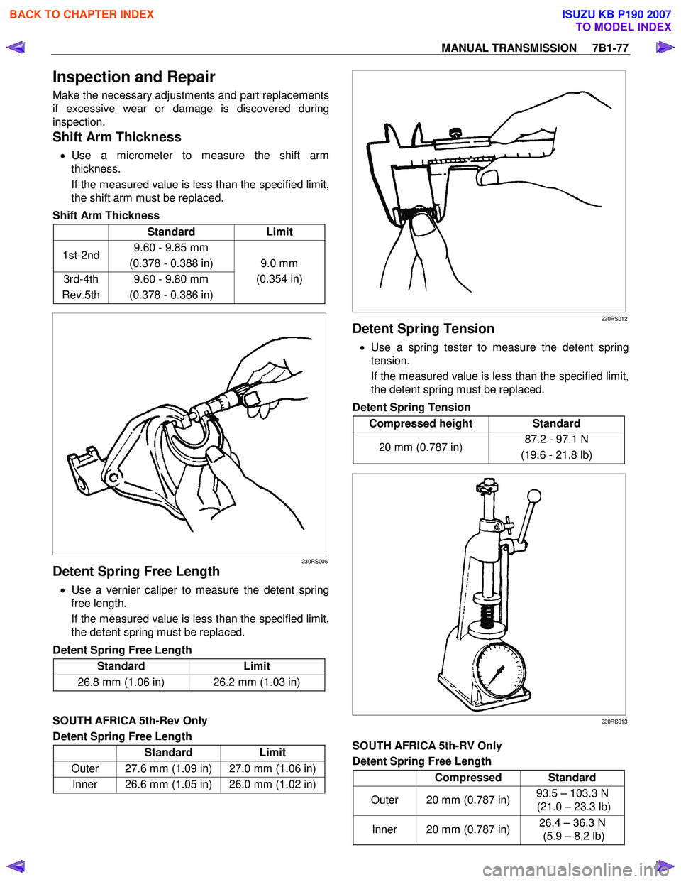
• Use a micrometer to measure the shift arm
thickness.
If the measured value is less than the specified limit,
the shift arm must be replaced.
Shift Arm Thickness
Standard Limit
1st-2nd 9.60 - 9.85 mm
(0.378 - 0.388 in)
3rd-4th
Rev.5th 9.60 - 9.80 mm
(0.378 - 0.386 in) 9.0 mm
(0.354 in)
230RS006
Detent Spring Free Length
• Use a vernier caliper to measure the detent spring
free length.
If the measured value is less than the specified limit,
the detent spring must be replaced.
Detent Spring Free Length
Standard Limit
26.8 mm (1.06 in) 26.2 mm (1.03 in)
SOUTH AFRICA 5th-Rev Only
Detent Spring Free Length
Standard Limit
Outer 27.6 mm (1.09 in) 27.0 mm (1.06 in)
Inner 26.6 mm (1.05 in) 26.0 mm (1.02 in)
220RS012
Detent Spring Tension
• Use a spring tester to measure the detent spring
tension.
If the measured value is less than the specified limit,
the detent spring must be replaced.
Detent Spring Tension
Compressed height Standard
20 mm (0.787 in) 87.2 - 97.1 N
(19.6 - 21.8 lb)
220RS013
SOUTH AFRICA 5th-RV Only
Detent Spring Free Length
Compressed Standard
Outer 20 mm (0.787 in) 93.5 – 103.3 N
(21.0 – 23.3 lb)
Inner 20 mm (0.787 in) 26.4 – 36.3 N
(5.9 – 8.2 lb)
BACK TO CHAPTER INDEX
TO MODEL INDEX
ISUZU KB P190 2007
Page 4750 of 6020
Manual Transmission (MUX) 7B1-31
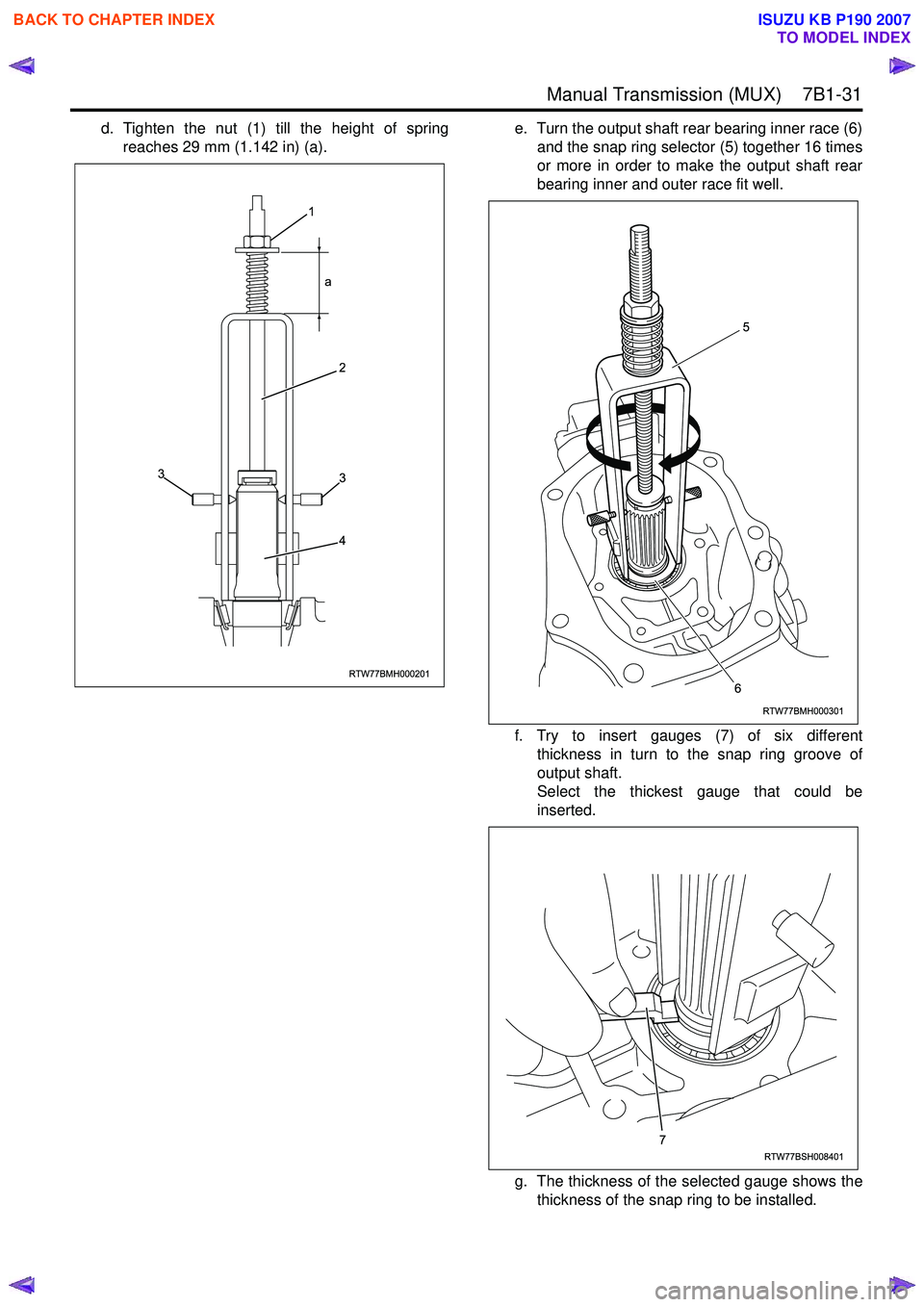
d. Tighten the nut (1) till the height of springreaches 29 mm (1.142 in) (a). e. Turn the output shaft rear bearing inner race (6)
and the snap ring selector (5) together 16 times
or more in order to make the output shaft rear
bearing inner and outer race fit well.
f. Try to insert gauges (7) of six different thickness in turn to the snap ring groove of
output shaft.
Select the thickest gauge that could be
inserted.
g. The thickness of the selected gauge shows the thickness of the snap ring to be installed.
RTW77BMH000201
1
a
2
3
4
3
RTW77BMH000301
5
6
RTW77BSH008401
7
BACK TO CHAPTER INDEX
TO MODEL INDEX
ISUZU KB P190 2007
Page 4805 of 6020
CLUTCH 7C-27
RTW 67CSH000101
Clutch Set Force
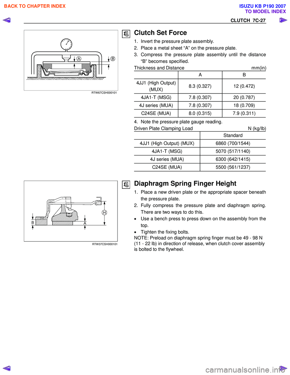
1. Invert the pressure plate assembly.
2. Place a metal sheet “A” on the pressure plate.
3. Compress the pressure plate assembly until the distance “B” becomes specified.
Thickness and Distance mm(in
)
A B
4JJ1 (High Output)
(MUX) 8.3 (0.327) 12 (0.472)
4JA1-T (MSG) 7.8 (0.307) 20 (0.787)
4J series (MUA) 7.8 (0.307) 18 (0.709)
C24SE (MUA) 8.0 (0.315) 7.9 (0.311)
4. Note the pressure plate gauge reading.
Driven Plate Clamping Load N (kg/Ib)
Standard
4JJ1 (High Output) (MUX) 6860 (700/1544)
4JA1-T (MSG) 5070 (517/1140)
4J series (MUA) 6300 (642/1415)
C24SE (MUA) 5500 (561/1237)
RTW 37CSH000101
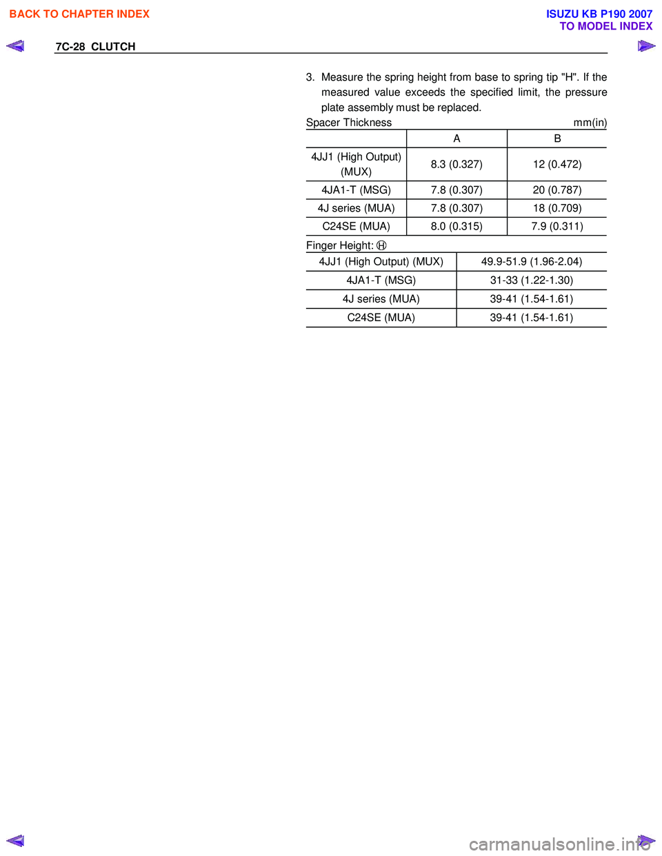
Diaphragm Spring Finger Height
1. Place a new driven plate or the appropriate spacer beneath
the pressure plate.
2. Fully compress the pressure plate and diaphragm spring. There are two ways to do this.
• Use a bench press to press down on the assembly from the
top.
• Tighten the fixing bolts.
NOTE: Preload on diaphragm spring finger must be 49 - 98 N
(11 - 22 lb) in direction of release, when clutch cover assembly
is bolted to the flywheel.
BACK TO CHAPTER INDEX
TO MODEL INDEX
ISUZU KB P190 2007
Page 4806 of 6020
7C-28 CLUTCH
3. Measure the spring height from base to spring tip "H". If the
measured value exceeds the specified limit, the pressure
plate assembly must be replaced.
Spacer Thickness mm(in)
A B
4JJ1 (High Output)
(MUX) 8.3 (0.327) 12 (0.472)
4JA1-T (MSG) 7.8 (0.307) 20 (0.787)
4J series (MUA) 7.8 (0.307) 18 (0.709)
C24SE (MUA) 8.0 (0.315) 7.9 (0.311)
Finger Height: H
4JJ1 (High Output) (MUX) 49.9-51.9 (1.96-2.04)
4JA1-T (MSG) 31-33 (1.22-1.30)
4J series (MUA) 39-41 (1.54-1.61)
C24SE (MUA) 39-41 (1.54-1.61)
BACK TO CHAPTER INDEX
TO MODEL INDEX
ISUZU KB P190 2007
Page 4860 of 6020
7D-30 TRANSFER CASE
Detent Spring Free Length
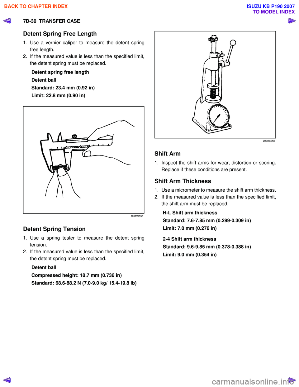
1. Use a vernier caliper to measure the detent spring
free length.
2. If the measured value is less than the specified limit,
the detent spring must be replaced.
Detent spring free length
Detent ball
Standard: 23.4 mm (0.92 in)
Limit: 22.8 mm (0.90 in)
220RW 035
Detent Spring Tension
1. Use a spring tester to measure the detent spring
tension.
2. If the measured value is less than the specified limit,
the detent spring must be replaced.
Detent ball
Compressed height: 18.7 mm (0.736 in)
Standard: 68.6-88.2 N (7.0-9.0 kg/ 15.4-19.8 lb)
220RS013
Shift Arm
1. Inspect the shift arms for wear, distortion or scoring.
Replace if these conditions are present.
Shift Arm Thickness
1. Use a micrometer to measure the shift arm thickness.
2. If the measured value is less than the specified limit,
the shift arm must be replaced.
H-L Shift arm thickness
Standard: 7.6-7.85 mm (0.299-0.309 in)
Limit: 7.0 mm (0.276 in)
2-4 Shift arm thickness
Standard: 9.6-9.85 mm (0.378-0.388 in)
Limit: 9.0 mm (0.354 in)
BACK TO CHAPTER INDEX
TO MODEL INDEX
ISUZU KB P190 2007
Page 5656 of 6020
SUPPLEMENTAL RESTRAINT SYSTEM 9A-21
On–Vehicle Service
Service Precaution
WARNING: WHEN PERFORMING SERVICE ON OR
AROUND SRS COMPONENTS OR SRS WIRING,
FOLLOW THE PROCEDURES LISTED BELOW TO
TEMPORARILY DISABLE THE SRS. FAILURE TO
FOLLOW PROCEDURES COULD RESULT IN
POSSIBLE AIR BAG DEPLOYMENT, PERSONAL
INJURY OR OTHERWISE UNNECESSARY SRS
REPAIRS.
The SRS control unit in Driver–Passenger SRS can
maintain sufficient voltage to cause a deployment fo
r
up to 15 seconds after the ignition switch is turned
“OFF,” the battery is disconnected, or the fuse
powering the SRS control unit is removed.
Many of the service procedures require removal of the
“SRS” fuse, and disconnection of the air bag assembl
y
from the deployment loop to avoid an accidental
deployment. If the air bag assembly is disconnected
from the deployment loop as noted in the “Disabling
the SRS” procedure that follows, service can begin
immediately without waiting for the 15 second time
period to expire.
Disabling The SRS
Removal
Turn the ignition switch to “LOCK” and remove the
key.
1. Remove the SRS fuse “SRS”, from the side of the driver’s side of the instrument panel fuse block o
r
disconnect the battery.
2. Disconnect the yellow connector at the base of the steering column.
3. Remove the glove box assembly, refer to “Passenger Air Bag Assembly Replacement” in
this manual.
4. Disconnect the yellow connector behind the glove box assembly.
CAUTION: With the “SRS” fuse removed and
ignition switched “ON”, the “SRS” warning lamp
will be “ON”. This is normal operation and does
not indicate an SRS malfunction.
Enabling The SRS
Installation
CAUTION: Never use the air bag assembly from
another vehicle or different model year air bag
assembly.
Use only a new air bag assembly matched to the
TFR/S which is being repaired.
Turn the ignition switch to “LOCK” and remove the
key.
1. Connect the yellow connector passenger air bag assembly.
2. Install the glove box assembly. Refer to “Passenger air bag assembly replacement” in this
manual.
3. Connect the yellow connector at the base of the steering column.
4. Install the “AIR BAG” fuse “SRS” to the side of the driver’s side of the instrument panel fuse block o
r
connect the battery.
Turn the ignition switch to “ON” and verify that the
“SRS” warning lamp flashes seven times and then
turns to “LOCK”. If it does not operate as described,
perform the “SRS Diagnostic System Check” in this
manual.
Handling / Installation / Diagnosis
1. The air bag assembly should not be subjected to temperatures above 65
°C (150°F).
2. The air bag assembly, and SRS control unit, should not be used if they have been dropped from
a height of 100 centimeters (3.28 feet) or more.
3. W hen the SRS control unit is replaced, it must be oriented with the arrow on the sensor pointing
toward the front of the vehicle. It is very important
for the SRS control unit to be located flat on the
mounting surface, parallel to the vehicle datum
line. It is important that the SRS control unit
mounting surface is free of any dirt or other foreign
material.
4. Do not apply power to the SRS unless all components are connected or a diagnostic chart
requests it, as this will set a diagnostic trouble
code.
5. The “SRS Diagnostic System Check” must be the starting point of any SRS diagnostics. The “SRS
Diagnostic System Check” will verify proper “SRS”
warning lamp operation and will lead you to the
correct chart to diagnose any SRS malfunctions.
Bypassing these procedures may result in
extended diagnostic time, incorrect diagnosis, and
incorrect parts replacement.
BACK TO CHAPTER INDEX TO MODEL INDEXISUZU KB P190 2007
Page 5667 of 6020
9A-32 SUPPLEMENTAL RESTRAINT SYSTEM
Service Precautions for SRS
Component Service
CAUTION: When fasteners are removed, always
reinstall them at the same location from which
they were removed. If a fastener needs to be
replaced, use the correct part number fastener fo
r
that application. If the correct part number
fastener is not available, a fastener of equal size
and strength (or stronger) may be used. Fasteners
that are not reused, and those requiring a thread
locking compound will be called out. The correct
torque value must be used when installing
fasteners that require it. If the above conditions
are not followed, parts or system damage could
result.
WARNING: WHEN PERFORMING SERVICE ON OR
AROUND SRS COMPONENTS OR SRS WIRING,
FOLLOW THE PROCEDURES LISTED BELOW TO
TEMPORARILY DISABLE THE SRS. FAILURE TO
FOLLOW PROCEDURES COULD RESULT IN
POSSIBLE AIR BAG DEPLOYMENT, PERSONAL
INJURY OR OTHERWISE UNNEEDED SRS
REPAIRS.
The SRS control unit in the Driver–Passenger SRS
can maintain sufficient voltage to cause a deployment
for up to 15 seconds after the ignition switch is turned
“OFF,” the battery is disconnected, or the fuse
powering the SRS control unit is removed.
Many of the service procedures require removal of the
“SRS” fuse, and disconnection of the air bag assembl
y
from the deployment loop to avoid an accidental
deployment. If the air bag assembly is disconnected
from the deployment loop as noted in the “Disabling
the SRS” procedure that follows, service can begin
immediately without waiting for the 15 second time
period to expire.
Disabling The SRS
Removal
Turn the ignition switch to “OFF” and turn the steering
wheel so that the vehicle's wheels are pointing straight
ahead.
1. Remove the SRS fuse “SRS” from the left dash side lower fuse block or disconnect the battery.
2. Disconnect the yellow connector at the base o
f
steering column.
3. Remove the glove box assembly; Refer to “Passenger air bag assembly replacement” in this
section.
4. Disconnect the passenger air bag assembly yello
w
connector behind the glove box assembly.
CAUTION: With the “SRS” fuse removed and the
ignition switch to “ON,” the “SRS” warning lamp
will be “ON.” This is normal operation and does
not indicate an SRS malfunction.
Enabling The SRS
Installation
Turn the ignition switch to “LOCK” and remove the
key.
1. Connect the yellow connector passenger air bag assembly.
2. Install the glove box assembly. Refer to “Passenger Air Bag Assembly Replacement” in
this section.
3. Connect the yellow connector at the base of the steering column.
4. Install the “AIR BAG” fuse “SRS” to the left dash side lower fuse block or connect the battery.
Turn the ignition switch to “ON” and verify that the
“SRS” warning lamp flashes seven times and then
turns to “LOCK”. If it does not operate as described,
perform the “SRS Diagnostic System Check” in this
section.
Handling / Installation / Diagnosis
1. Air bag assembly should not be subjected to
temperatures above 65 °C (150 °F).
2.
Air bag assembly, and SRS control unit should not
be used if they have been dropped from a height
of 100 centimeters (3.28 feet) or more.
3. W hen a SRS control unit is replaced, it must be oriented with the arrow on the SRS control unit
pointing toward the front of the vehicle. It is ver
y
important for the SRS control unit to be located flat
on the mounting surface, parallel to the vehicle
datum line. It is important that the SRS control unit
mounting surface is free of any dirt or other foreign
material.
4. Do not apply power to the SRS unless all components are connected or a diagnostic chart
requests it, as this will set a diagnostic trouble
code.
5. The “SRS Diagnostic System Check” must be the starting point of any SRS diagnostics. The “SRS
Diagnostic System Check” will verify proper “SRS”
warning lamp operation and will lead you to the
correct chart to diagnose any SRS malfunctions.
Bypassing these procedures may result in
extended diagnostic time, incorrect diagnosis, and
incorrect parts replacements.
BACK TO CHAPTER INDEX TO MODEL INDEXISUZU KB P190 2007
Page 5850 of 6020
10-92 CAB
Important Operations - Removal
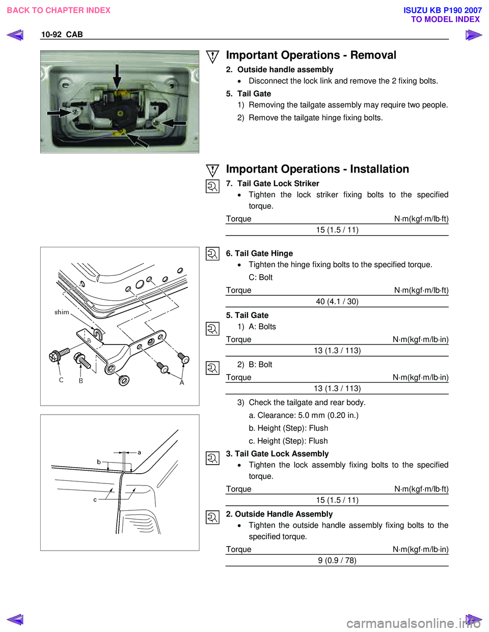
2. Outside handle assembly • Disconnect the lock link and remove the 2 fixing bolts.
5. Tail Gate 1) Removing the tailgate assembly may require two people.
2) Remove the tailgate hinge fixing bolts.
Important Operations - Installation
7. Tail Gate Lock Striker • Tighten the lock striker fixing bolts to the specified
torque.
Torque N ⋅m(kgf ⋅m/lb ⋅ft)
15 (1.5 / 11)
6. Tail Gate Hinge • Tighten the hinge fixing bolts to the specified torque.
C: Bolt
Torque N ⋅m(kgf ⋅m/lb ⋅ft)
40 (4.1 / 30)
5. Tail Gate 1) A: Bolts
Torque N ⋅m(kgf ⋅m/lb ⋅in)
13 (1.3 / 113)
2) B: Bolt
Torque N ⋅m(kgf ⋅m/lb ⋅in)
13 (1.3 / 113)
3) Check the tailgate and rear body.
a. Clearance: 5.0 mm (0.20 in.)
b. Height (Step): Flush
c. Height (Step): Flush
3. Tail Gate Lock Assembly • Tighten the lock assembly fixing bolts to the specified
torque.
Torque N ⋅m(kgf ⋅m/lb ⋅ft)
15 (1.5 / 11)
2. Outside Handle Assembly • Tighten the outside handle assembly fixing bolts to the
specified torque.
Torque N ⋅m(kgf ⋅m/lb ⋅in)
9 (0.9 / 78)
BACK TO CHAPTER INDEX TO MODEL INDEXISUZU KB P190 2007