Page 1448 of 6020

6A-88 ENGINE MECHANICAL (4JK1/4JJ1)
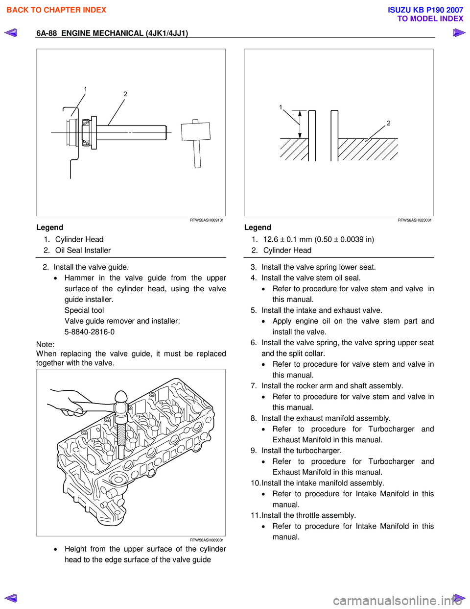
RTW 56ASH009101
Legend
1. Cylinder Head
2. Oil Seal Installer
2. Install the valve guide.
• Hammer in the valve guide from the uppe
r
surface of the cylinder head, using the valve
guide installer.
Special tool
Valve guide remover and installer:
5-8840-2816-0
Note:
W hen replacing the valve guide, it must be replaced
together with the valve.
RTW 56ASH009001
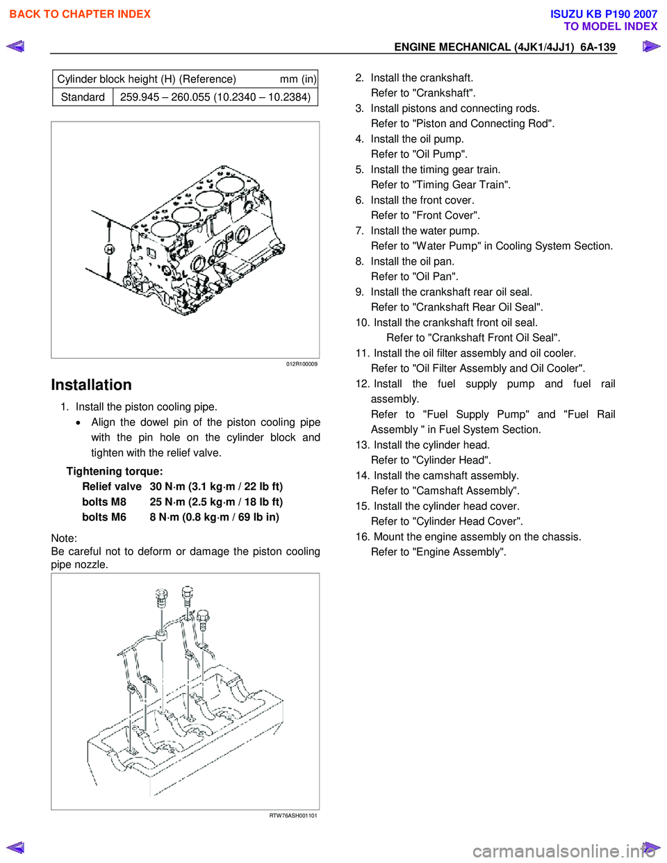
• Height from the upper surface of the cylinder
head to the edge surface of the valve guide
RTW 56ASH023001
Legend
1. 12.6 ± 0.1 mm (0.50 ± 0.0039 in)
2. Cylinder Head
3. Install the valve spring lower seat.
4. Install the valve stem oil seal. • Refer to procedure for valve stem and valve in
this manual.
5. Install the intake and exhaust valve. • Apply engine oil on the valve stem part and
install the valve.
6. Install the valve spring, the valve spring upper seat and the split collar.
• Refer to procedure for valve stem and valve in
this manual.
7. Install the rocker arm and shaft assembly. • Refer to procedure for valve stem and valve in
this manual.
8. Install the exhaust manifold assembly. • Refer to procedure for Turbocharger and
Exhaust Manifold in this manual.
9. Install the turbocharger. • Refer to procedure for Turbocharger and
Exhaust Manifold in this manual.
10. Install the intake manifold assembly. • Refer to procedure for Intake Manifold in this
manual.
11. Install the throttle assembly. • Refer to procedure for Intake Manifold in this
manual.
BACK TO CHAPTER INDEX
TO MODEL INDEX
ISUZU KB P190 2007
Page 1499 of 6020

ENGINE MECHANICAL (4JK1/4JJ1) 6A-139
Cylinder block height (H) (Reference) mm (in)
Standard 259.945 – 260.055 (10.2340 – 10.2384)
012R100009
Installation
1. Install the piston cooling pipe.
• Align the dowel pin of the piston cooling pipe
with the pin hole on the cylinder block and
tighten with the relief valve.
Tightening torque: Relief valve 30 N ⋅
⋅⋅
⋅
m (3.1 kg ⋅
⋅⋅
⋅
m / 22 lb ft)
bolts M8 25 N ⋅
⋅⋅
⋅
m (2.5 kg ⋅
⋅⋅
⋅
m / 18 lb ft)
bolts M6 8 N ⋅
⋅⋅
⋅
m (0.8 kg ⋅
⋅⋅
⋅
m / 69 lb in)
Note:
Be careful not to deform or damage the piston cooling
pipe nozzle.
RTW 76ASH001101
2. Install the crankshaft.
Refer to "Crankshaft".
3. Install pistons and connecting rods.
Refer to "Piston and Connecting Rod".
4. Install the oil pump.
Refer to "Oil Pump".
5. Install the timing gear train.
Refer to "Timing Gear Train".
6. Install the front cover.
Refer to "Front Cover".
7. Install the water pump.
Refer to "W ater Pump" in Cooling System Section.
8. Install the oil pan.
Refer to "Oil Pan".
9. Install the crankshaft rear oil seal.
Refer to "Crankshaft Rear Oil Seal".
10. Install the crankshaft front oil seal. Refer to "Crankshaft Front Oil Seal".
11. Install the oil filter assembly and oil cooler.
Refer to "Oil Filter Assembly and Oil Cooler".
12. Install the fuel supply pump and fuel rail assembly.
Refer to "Fuel Supply Pump" and "Fuel Rail Assembly " in Fuel System Section.
13. Install the cylinder head.
Refer to "Cylinder Head".
14. Install the camshaft assembly.
Refer to "Camshaft Assembly".
15. Install the cylinder head cover.
Refer to "Cylinder Head Cover".
16. Mount the engine assembly on the chassis.
Refer to "Engine Assembly".
BACK TO CHAPTER INDEX
TO MODEL INDEX
ISUZU KB P190 2007
Page 1600 of 6020
6D-12 ENGINE ELECTRICAL (4JK1/4JJ1)
4. Check for conductivity between the slip rings and
the rotor core. If there is continuity, the roto
r
assembly must be replaced.
066RS017
Stator Coil
1. Measure the stator coil resistance. If the
resistance is less than the specified value, the
stator coil must be replaced.
Stator coil resistance
0.07Ω at 20 °C (68 °F)
066RS034
2. Measure the resistance between the stator coil
and the stator core. If the resistance is less than
the specified value, the stator coil must be
replaced.
Stator coil/core resistance MΩ
1
066RS035
Brushes
Measure the brush height. If the height is less than the
specified limit, the brushes must be replaced.
Brush height mm (in)
Standard 18 (0.709)
Limit 5.5 (0.217)
066RW 024
BACK TO CHAPTER INDEX
TO MODEL INDEX
ISUZU KB P190 2007
Page 2053 of 6020
ENGINE MECHANICAL (C24SE) 6A-39
Camshaft Housing, Check for Plane Surface
Clean
Sealing surfaces.
Inspection
Check length and width of sealing surface for deformation and
diagnosis for warpage and use straight edge feeler gauge.
Measure
Height of camshaft housing (sealing surface to sealing
surface).
Dimension I: (74.0 mm)
Cylinder Head, Removal and Installation
Important
Only remove cylinder head with engine cold (room
temperature).
Removal
1. Remove the alternator, power steering and V-belts.
Removal
2. Loosen the fastening bolts from alternator.
3. Loosen the lower alternator fastening bolt by swinging the alternator to the rear.
Removal
4. Remove the front toothed belt cover.
5. Remove the toothed belt from camshaft pulley.
See operation "Timing Check and Adjust".
BACK TO CHAPTER INDEX
TO MODEL INDEX
ISUZU KB P190 2007
Page 2093 of 6020

ENGINE MECHANICAL (C24SE) 6A-79
Adjustment Values/Checking Values
Valve clearance Inlet Hydraulic valve lash adjustment
Outlet No adjustment necessary
Spark plugs - electrode gap 1.0 ∼ 1.1mm
Compression The difference in compression
between the individual cylinders
in the engine must not exceed
100 kPa (1 bar).
Pressure loss The pressure loss of an engine
in perfect condition per cylinder
is not more than max. 25%
Cylinder Head
Cylinder Head Gasket
Thickness - installed mm 1.2
Valve seat width at cylinder head
inlet mm 1.0 to 1.5
outlet mm 1.7 to 2.2
Valve stem play inlet mm 0.018 to 0.052
outlet mm 0.038 to 0.072
Permissible valve stem to cone runout
inlet mm 0.03
outlet mm 0.33
Overall height of cylinder head
(Sealing surface to sealing surface) mm 95.5 ± 0.25
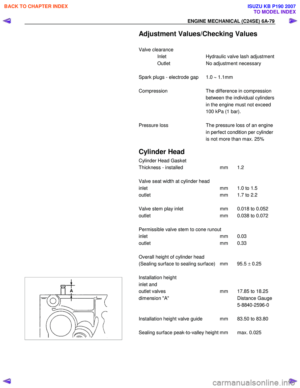
Installation height
inlet and
outlet valves mm 17.85 to 18.25
dimension "A" Distance Gauge
5-8840-2596-0
Installation height valve guide mm 83.50 to 83.80
Sealing surface peak-to-valley height mm max. 0.025
BACK TO CHAPTER INDEX
TO MODEL INDEX
ISUZU KB P190 2007
Page 2096 of 6020

6A-82 ENGINE MECHANICAL (C24SE)
Crankshaft, Cylinder Block
Cylinder Grinding and Piston Dimensions
Size Cylinder bore dia. in mm Cylinder to Related piston dia. in mm Piston head
Crankshaft co- efficient
housing
co-efficient
over to over to
Production
(2.4L) 1 87.48
87.49 87.49
87.50 99
00 87.46
87.47 87.47
87.48 99
00
Customer service (2.4L) - 87.99 88.00 0+0.5 87.97 87.98 7+0.5
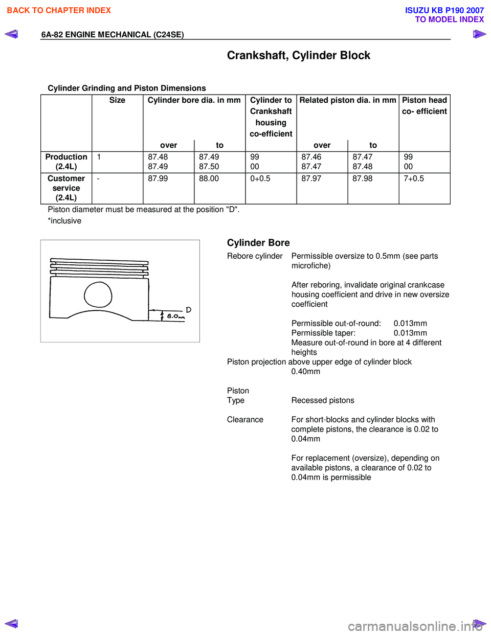
Piston diameter must be measured at the position "D".
*inclusive
Cylinder Bore
Rebore cylinder Permissible oversize to 0.5mm (see parts
microfiche)
After reboring, invalidate original crankcase
housing coefficient and drive in new oversize
coefficient
Permissible out-of-round: 0.013mm
Permissible taper: 0.013mm
Measure out-of-round in bore at 4 different
heights
Piston projection above upper edge of cylinder block 0.40mm
Piston
Type Recessed pistons
Clearance For short-blocks and cylinder blocks with complete pistons, the clearance is 0.02 to
0.04mm
For replacement (oversize), depending on
available pistons, a clearance of 0.02 to
0.04mm is permissible
BACK TO CHAPTER INDEX
TO MODEL INDEX
ISUZU KB P190 2007
Page 2097 of 6020
ENGINE MECHANICAL (C24SE) 6A-83
Crankshaft, Cylinder Block (continued)
Piston Rings
2.4L
Square ring Height mm 1.2
Tapered ring Height mm 1.5
Oil scraper Height mm 2.5
Ring gap offset 180 °
Note that the upper steel band ring gap is offset 25 to 50mm to
the left and the lower 25 to 50mm to the right opposite the
intermediate ring gap.
Piston Pin
Length mm 61.5
Diameter mm 21
Type Shrunk into con-rod
Play mm 2.4L
in piston 0.010-0.015
in con-rod none
Installation W hen installing piston pins,
heat con-rods to approx.
280 °C in oil bath. This
temperature should under no
circumstances be exceeded.
Crankshaft, Cylinder Block (continued)
The permissible weight variation of con-rods without piston and
bearing shell inside an engine is 8 g.
As the con-rods do not have balancing studs, reworking is not
possible.
Con-rods can only be replaced in sets.
BACK TO CHAPTER INDEX
TO MODEL INDEX
ISUZU KB P190 2007
Page 2101 of 6020
ENGINE MECHANICAL (C24SE) 6A-87
Crankshaft, Cylinder Block (continued)
Flywheel
Starter ring gear Before fitting, heat ring gear to 180 °C -
230 °C
Lateral run-out Permissible lateral run-out of installed
starter ring gear to flywheel: 0.5mm
Precision turning Permissible removal of material in clutch disc lining surface area: 0.3mm
In order to achieve the functional
relationship again after removal of material,
the same removal of material must take
place on the fore part of the flywheel
(contact for clutch assembly)
Dimension A: 2.1 to 2.2mm
Cylinder block
Top deck flatness mm 0.05
Cylinder block height mm 280 ±0.075
BACK TO CHAPTER INDEX
TO MODEL INDEX
ISUZU KB P190 2007