2007 ISUZU KB P190 engine overheat
[x] Cancel search: engine overheatPage 3753 of 6020
Exhaust System – V6 Page 6F – 5
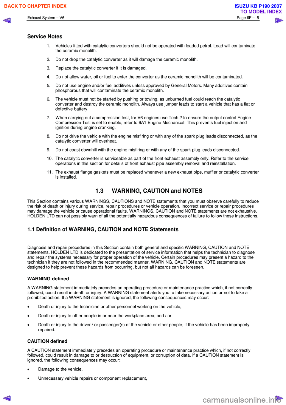
Service Notes
1. Vehicles fitted with catalytic converters should not be operated with leaded petrol. Lead will contaminate
the ceramic monolith.
2. Do not drop the catalytic converter as it will damage the ceramic monolith.
3. Replace the catalytic converter if it is damaged.
4. Do not allow water, oil or fuel to enter the converter as the ceramic monolith will be contaminated.
5. Do not use engine and/or fuel additives unless approved by General Motors. Many additives contain phosphorous that will contaminate the ceramic monolith.
6. The vehicle must not be started by pushing or towing, as unburned fuel could reach the catalytic converter and destroy the ceramic monolith. Always use jumper leads to start a vehicle that has a flat or
defective battery.
7. W hen carrying out a compression test, for V6 engines use Tech 2 to ensure the output control Engine Compression Test is set to enable, refer to 6A1 Engine Mechanical. This prevents fuel injection and
ignition during engine cranking.
8. Do not drive the vehicle with the engine misfiring or with any of the spark plug leads disconnected, as the catalytic converter will overheat.
9. Do not coast downhill with the engine misfiring or with any of the spark plug leads disconnected.
10. The catalytic converter is serviceable as part of the front exhaust assembly only. Refer to the service operations in this section for details of front exhaust pipe assembly removal and reinstallation.
11. The exhaust flange gaskets must be replaced whenever a new exhaust pipe, muffler or catalytic converter is installed.
1.3 WARNING, CAUTION and NOTES
This Section contains various W ARNINGS, CAUTIONS and NOTE statements that you must observe carefully to reduce
the risk of death or injury during service, repair procedures or vehicle operation. Incorrect service or repair procedures
may damage the vehicle or cause operational faults. W ARNINGS, CAUTION and NOTE statements are not exhaustive.
HOLDEN LTD can not possibly warn of all the potentially hazardous consequences of failure to follow these instructions.
1.1 Definition of WARNING, CAUTION and NOTE Statements
Diagnosis and repair procedures in this Section contain both general and specific W ARNING, CAUTION and NOTE
statements. HOLDEN LTD is dedicated to the presentation of service information that helps the technician to diagnose
and repair the systems necessary for proper operation of the vehicle. Certain procedures may present a hazard to the
technician if they are not followed in the recommended manner. W ARNING, CAUTION and NOTE statements are
designed to help prevent these hazards from occurring, but not all hazards can be foreseen.
WARNING defined
A W ARNING statement immediately precedes an operating procedure or maintenance practice which, if not correctly
followed, could result in death or injury. A W ARNING statement alerts you to take necessary action or not to take a
prohibited action. If a W ARNING statement is ignored, the following consequences may occur:
• Death or injury to the technician or other personnel working on the vehicle,
• Death or injury to other people in or near the workplace area, and / or
• Death or injury to the driver / or passenger(s) of the vehicle or other people, if the vehicle has been improperly
repaired.
CAUTION defined
A CAUTION statement immediately precedes an operating procedure or maintenance practice which, if not correctly
followed, could result in damage to or destruction of equipment, or corruption of data. If a CAUTION statement is
ignored, the following consequences may occur:
• Damage to the vehicle,
• Unnecessary vehicle repairs or component replacement,
BACK TO CHAPTER INDEX
TO MODEL INDEX
ISUZU KB P190 2007
Page 3820 of 6020
Automatic Transmission – 4L60E – Electrical Diagnosis Page 7C2–34
• The TCM records the operating conditions when the conditions for setting the DTC are met. The TCM stores this
information as Failure Records.
• The TCM stores DTC P0218 in TCM history.
Conditions for Clearing the DTC
• Tech 2 can clear the DTC.
• The TCM clears the DTC from TCM history if the vehicle completes 40 warm-up cycles without a non-emission
related diagnostic fault occurring.
• The TCM cancels the DTC default actions when the fault no longer exists and the DTC passes.
Diagnostic Aids
• Tech 2’s Transmission Fluid Temp. should rise steadily to a normal operating temperature, then stabilise.
• Ask about the customer's driving habits, trailer towing, etc. Trailer towing should occur in D3.
• Refer to Symptoms - Automatic Transmission in 7C3 Automatic Transmission – 4L60E – Hydraulic and Mechanical
Diagnosis.
Test Description
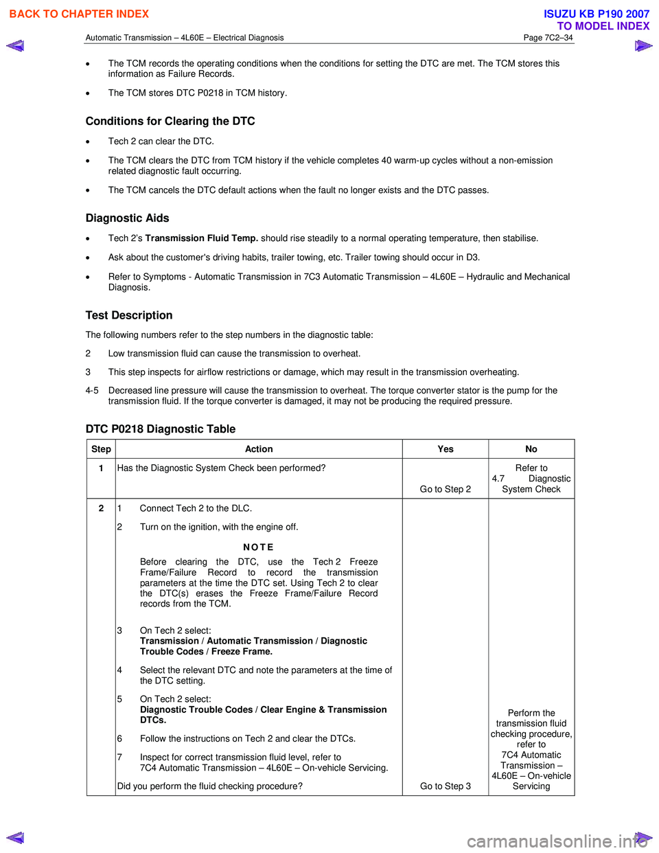
The following numbers refer to the step numbers in the diagnostic table:
2 Low transmission fluid can cause the transmission to overheat.
3 This step inspects for airflow restrictions or damage, which may result in the transmission overheating.
4-5 Decreased line pressure will cause the transmission to overheat. The torque converter stator is the pump for the transmission fluid. If the torque converter is damaged, it may not be producing the required pressure.
DTC P0218 Diagnostic Table
Step Action Yes No
1 Has the Diagnostic System Check been performed?
Go to Step 2 Refer to
4.7 Diagnostic System Check
2 1 Connect Tech 2 to the DLC.
2 Turn on the ignition, with the engine off.
NOTE
Before clearing the DTC, use the Tech 2 Freeze
Frame/Failure Record to record the transmission
parameters at the time the DTC set. Using Tech 2 to clear
the DTC(s) erases the Freeze Frame/Failure Record
records from the TCM.
3 On Tech 2 select: Transmission / Automatic Transmission / Diagnostic
Trouble Codes / Freeze Frame.
4 Select the relevant DTC and note the parameters at the time of the DTC setting.
5 On Tech 2 select:
Diagnostic Trouble Codes / Clear Engine & Transmission
DTCs.
6 Follow the instructions on Tech 2 and clear the DTCs.
7 Inspect for correct transmission fluid level, refer to 7C4 Automatic Transmission – 4L60E – On-vehicle Servicing.
Did you perform the fluid checking procedure? Go to Step 3 Perform the
transmission fluid
checking procedure, refer to
7C4 Automatic
Transmission –
4L60E – On-vehicle Servicing
BACK TO CHAPTER INDEX
TO MODEL INDEX
ISUZU KB P190 2007
Page 4381 of 6020
TRANSMISSION CONTROL SYSTEM (JR405E) 7A2-97
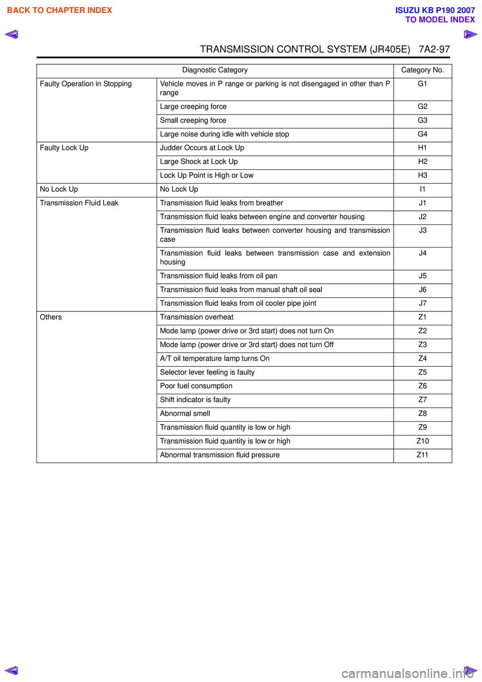
Faulty Operation in Stopping Vehicle moves in P range or parking is not disengaged in other than Prange G1
Large creeping force G2
Small creeping force G3
Large noise during idle with vehicle stop G4
Faulty Lock Up Judder Occurs at Lock Up H1
Large Shock at Lock Up H2
Lock Up Point is High or Low H3
No Lock Up No Lock Up I1
Transmission Fluid Leak Transmission fluid leaks from breather J1
Transmission fluid leaks between engine and converter housing J2
Transmission fluid leaks between converter housing and transmission
case J3
Transmission fluid leaks between transmission case and extension
housing J4
Transmission fluid leaks from oil pan J5
Transmission fluid leaks from manual shaft oil seal J6
Transmission fluid leaks from oil cooler pipe joint J7
Others Transmission overheat Z1
Mode lamp (power drive or 3rd start) does not turn On Z2
Mode lamp (power drive or 3rd start) does not turn Off Z3
A/T oil temperature lamp turns On Z4
Selector lever feeling is faulty Z5
Poor fuel consumption Z6
Shift indicator is faulty Z7
Abnormal smell Z8
Transmission fluid quantity is low or high Z9
Transmission fluid quantity is low or high Z10
Abnormal transmission fluid pressure Z11
Diagnostic Category
Category No.
BACK TO CHAPTER INDEX
TO MODEL INDEX
ISUZU KB P190 2007
Page 4385 of 6020
TRANSMISSION CONTROL SYSTEM (JR405E) 7A2-101
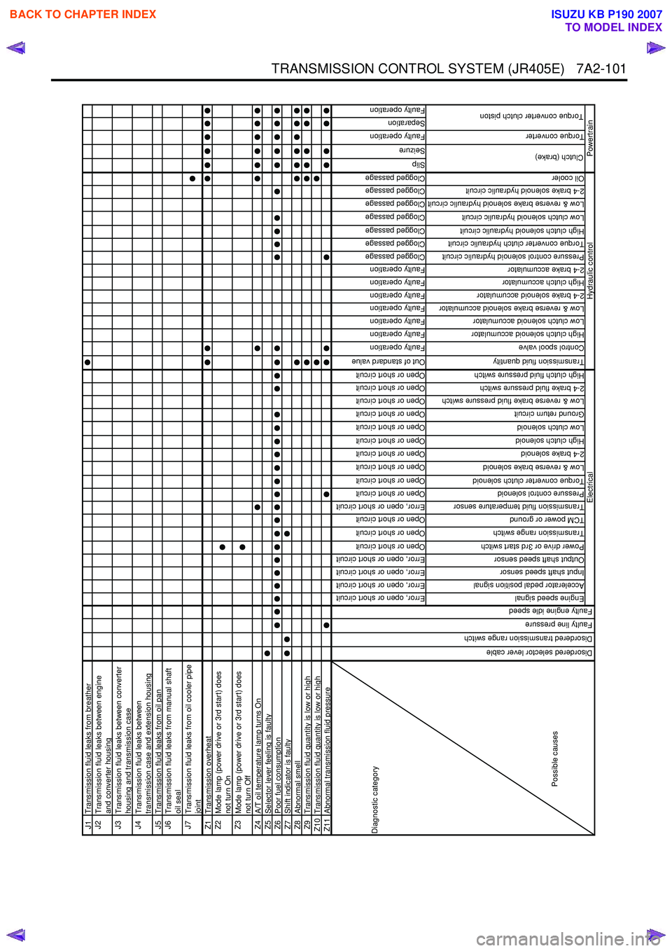
J1Transmission fluid leaks from breatherJ2
Transmission fluid leaks between engine
and converter housing
J3
Transmission fluid leaks between converter
housing and transmission case
J4
Transmission fluid leaks between
transmission case and extension housing
J5 Transmission fluid leaks from oil panJ6
Transmission fluid leaks from manual shaft
oil seal
J7
Transmission fluid leaks from oil cooler pipe
joint
Z1 Transmission overheatZ2
Mode lamp (power drive or 3rd start) does
not turn On
Z3
Mode lamp (power drive or 3rd start) does
not turn Off
Z4 A/T oil temperature lamp turns OnZ5Selector lever feeling is faultyZ6Poor fuel consumptionZ7Shift indicator is faultyZ8Abnormal smellZ9Transmission fluid quantity is low or highZ10 Transmission fluid quantity is low or highZ11Abnormal transmission fluid pressure
Error, open or short circuit
Error, open or short circuit
Error, open or short circuit
Error, open or short circuit
Open or short circuit
Open or short circuit
Open or short circuit
Error, open or short circuit
Open or short circuit
Open or short circuit
Open or short circuit
Open or short circuit
Open or short circuit
Open or short circuit
Open or short circuit
Open or short circuit
Open or short circuit
Open or short circuit
Out of standard value
Faulty operation
Faulty operation
Faulty operation
Faulty operation
Faulty operation
Faulty operation
Faulty operation
Clogged passage
Clogged passage
Clogged passage
Clogged passage
Clogged passage
Clogged passage
Clogged passage
Slip
Seizure
Faulty operation
Separation
Faulty operation
Engine speed signal
Accelerator pedal position signal
Input shaft speed sensor
Output shaft speed sensor
Power drive or 3rd start switch
Transmission range switch
TCM power or ground
Transmission fluid temperature sensor
Pressure control solenoid
Torque converter clutch solenoid
Low & reverse brake solenoid
2-4 brake solenoid
High clutch solenoid
Low clutch solenoid
Ground return circuit
Low & reverse brake fluid pressure switch
2-4 brake fluid pressure switch
High clutch fluid pressure switch
Transmission fluid quantity
Control spool valve
High clutch solenoid accumulator
Low clutch solenoid accumulator
Low & reverse brake solenoid accumulator
2-4 brake solenoid accumulator
High clutch accumulator
2-4 brake accumulator
Pressure control solenoid hydraulic circuit
Torque converter clutch hydraulic circuit
High clutch solenoid hydraulic circuit
Low clutch solenoid hydraulic circuit
Low & reverse brake solenoid hydraulic circuit
2-4 brake solenoid hydraulic circuit
Oil cooler
Torque converter
Clutch (brake)
Torque converter clutch piston
Hydraulic control
Powertrain
Diagnostic category
Possible causes
Electrical
Disordered selector lever cable
Disordered transmission range switch
Faulty line pressure
Faulty engine idle speed
BACK TO CHAPTER INDEX
TO MODEL INDEX
ISUZU KB P190 2007
Page 4402 of 6020
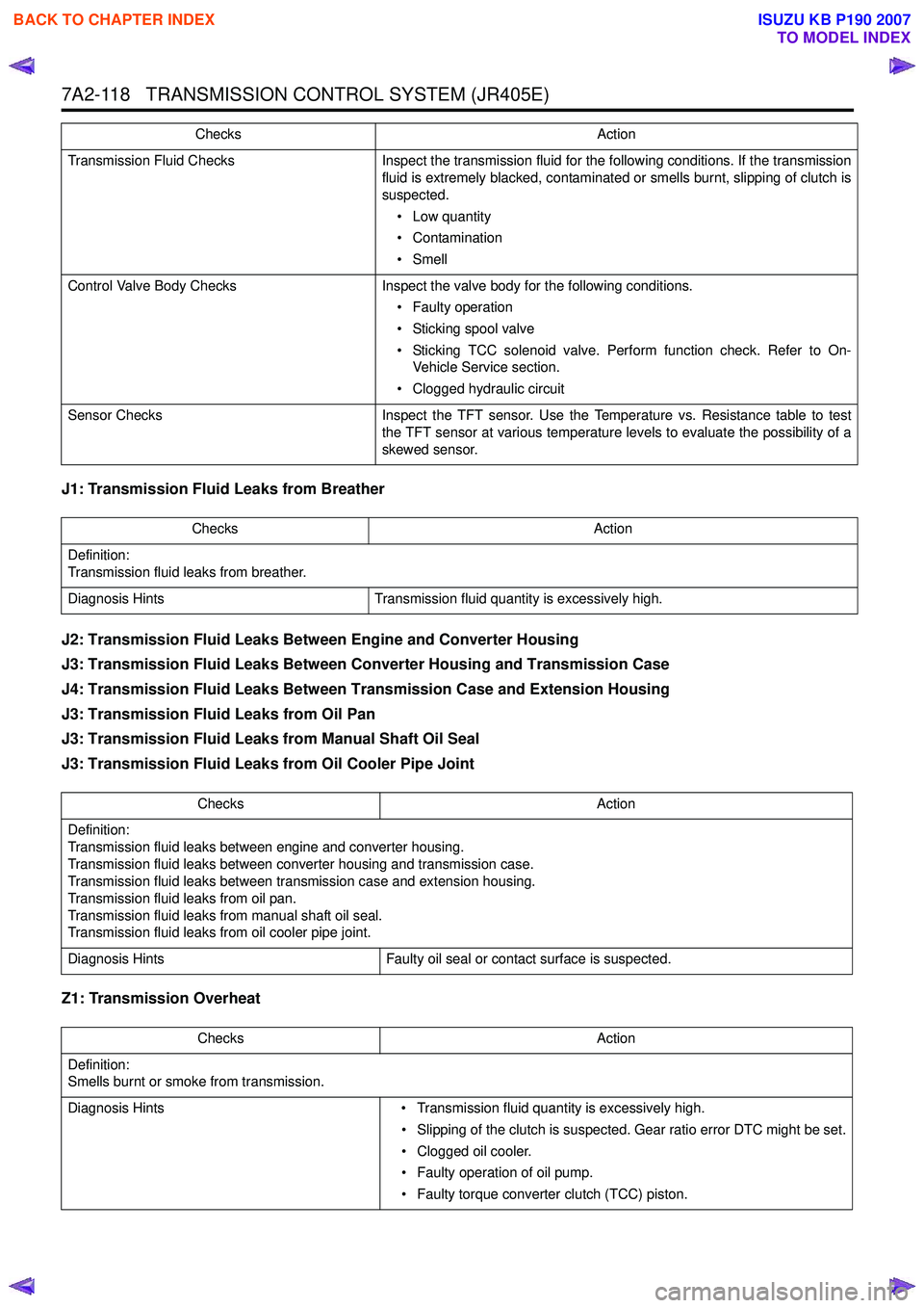
7A2-118 TRANSMISSION CONTROL SYSTEM (JR405E)
J1: Transmission Fluid Leaks from Breather
J2: Transmission Fluid Leaks Between Engine and Converter Housing
J3: Transmission Fluid Leaks Between Converter Housing and Transmission Case
J4: Transmission Fluid Leaks Between Transmission Case and Extension Housing
J3: Transmission Fluid Leaks from Oil Pan
J3: Transmission Fluid Leaks from Manual Shaft Oil Seal
J3: Transmission Fluid Leaks from Oil Cooler Pipe Joint
Z1: Transmission Overheat
Transmission Fluid Checks Inspect the transmission fluid for the following conditions. If the transmission
fluid is extremely blacked, contaminated or smells burnt, slipping of clutch is
suspected.
• Low quantity
• Contamination
• Smell
Control Valve Body Checks Inspect the valve body for the following conditions.
• Faulty operation
• Sticking spool valve
• Sticking TCC solenoid valve. Perform function check. Refer to On- Vehicle Service section.
• Clogged hydraulic circuit
Sensor Checks Inspect the TFT sensor. Use the Temperature vs. Resistance table to test
the TFT sensor at various temperature levels to evaluate the possibility of a
skewed sensor.
Checks
Action
Checks Action
Definition:
Transmission fluid leaks from breather.
Diagnosis Hints Transmission fluid quantity is excessively high.
Checks Action
Definition:
Transmission fluid leaks between engine and converter housing.
Transmission fluid leaks between converter housing and transmission case.
Transmission fluid leaks between transmission case and extension housing.
Transmission fluid leaks from oil pan.
Transmission fluid leaks from manual shaft oil seal.
Transmission fluid leaks from oil cooler pipe joint.
Diagnosis Hints Faulty oil seal or contact surface is suspected.
Checks Action
Definition:
Smells burnt or smoke from transmission.
Diagnosis Hints • Transmission fluid quantity is excessively high.
• Slipping of the clutch is suspected. Gear ratio error DTC might be set.
• Clogged oil cooler.
• Faulty operation of oil pump.
• Faulty torque converter clutch (TCC) piston.
BACK TO CHAPTER INDEX
TO MODEL INDEX
ISUZU KB P190 2007
Page 4403 of 6020
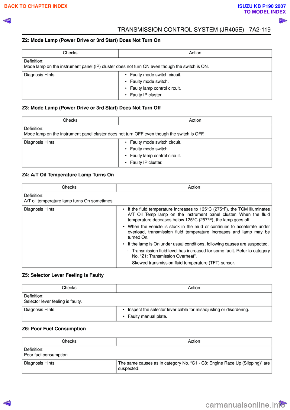
TRANSMISSION CONTROL SYSTEM (JR405E) 7A2-119
Z2: Mode Lamp (Power Drive or 3rd Start) Does Not Turn On
Z3: Mode Lamp (Power Drive or 3rd Start) Does Not Turn Off
Z4: A/T Oil Temperature Lamp Turns On
Z5: Selector Lever Feeling is Faulty
Z6: Poor Fuel Consumption
Checks Action
Definition:
Mode lamp on the instrument panel (IP) cluster does not turn ON even though the switch is ON.
Diagnosis Hints • Faulty mode switch circuit.
• Faulty mode switch.
• Faulty lamp control circuit.
• Faulty IP cluster.
Checks Action
Definition:
Mode lamp on the instrument panel cluster does not turn OFF even though the switch is OFF.
Diagnosis Hints • Faulty mode switch circuit.
• Faulty mode switch.
• Faulty lamp control circuit.
• Faulty IP cluster.
Checks Action
Definition:
A/T oil temperature lamp turns On sometimes.
Diagnosis Hints • If the fluid temperature increases to 135°C (275 °F), the TCM illuminates
A/T Oil Temp lamp on the instrument panel cluster. When the fluid
temperature deceases below 125 °C (257 °F), the lamp goes off.
• When the vehicle is stuck in the mud or continues to accelerate under overload, transmission fluid temperature increases and lamp may be
turned On.
• If the lamp is On under usual conditions, following causes are suspected. - Transmission fluid level has increased for some fault. Refer to category No. “Z1: Transmission Overheat”.
- Skewed transmission fluid temperature (TFT) sensor.
Checks Action
Definition:
Selector lever feeling is faulty.
Diagnosis Hints • Inspect the selector lever cable for misadjusting or disordering.
• Faulty manual plate.
Checks Action
Definition:
Poor fuel consumption.
Diagnosis Hints The same causes as in category No. “C1 - C8: Engine Race Up (Slipping)” are
suspected.
BACK TO CHAPTER INDEX
TO MODEL INDEX
ISUZU KB P190 2007