2007 ISUZU KB P190 engine overheat
[x] Cancel search: engine overheatPage 2109 of 6020
ENGINE COOLING 6B-5
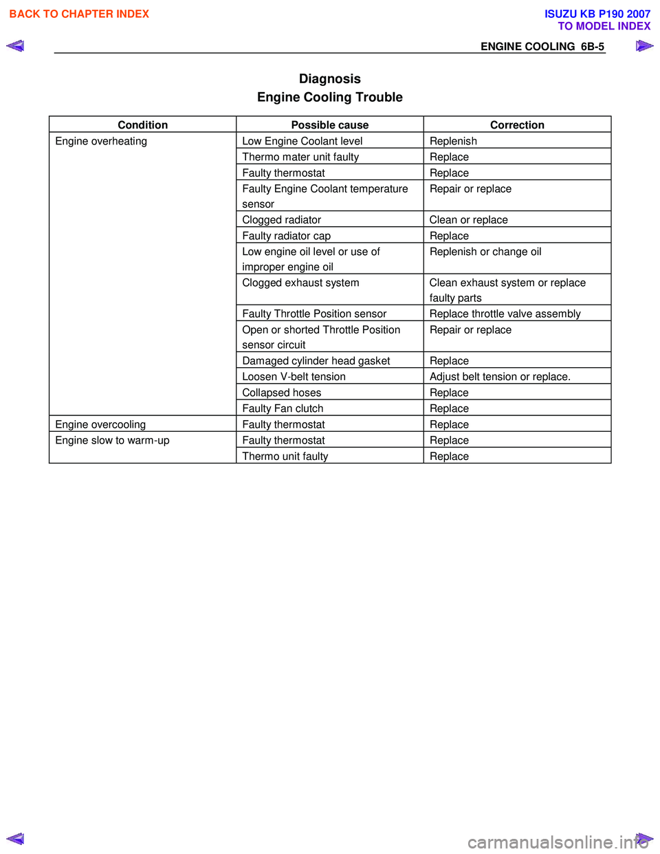
Diagnosis
Engine Cooling Trouble
Condition Possible cause Correction
Engine overheating Low Engine Coolant level Replenish
Thermo mater unit faulty Replace
Faulty thermostat Replace
Faulty Engine Coolant temperature
sensor Repair or replace
Clogged radiator Clean or replace
Faulty radiator cap Replace
Low engine oil level or use of
improper engine oil Replenish or change oil
Clogged exhaust system Clean exhaust system or replace
faulty parts
Faulty Throttle Position sensor Replace throttle valve assembly
Open or shorted Throttle Position
sensor circuit Repair or replace
Damaged cylinder head gasket Replace
Loosen V-belt tension Adjust belt tension or replace.
Collapsed hoses Replace
Faulty Fan clutch Replace
Engine overcooling Faulty thermostat Replace
Engine slow to warm-up Faulty thermostat Replace
Thermo unit faulty Replace
BACK TO CHAPTER INDEX
TO MODEL INDEX
ISUZU KB P190 2007
Page 2116 of 6020
6B-12 ENGINE COOLING
Inspection
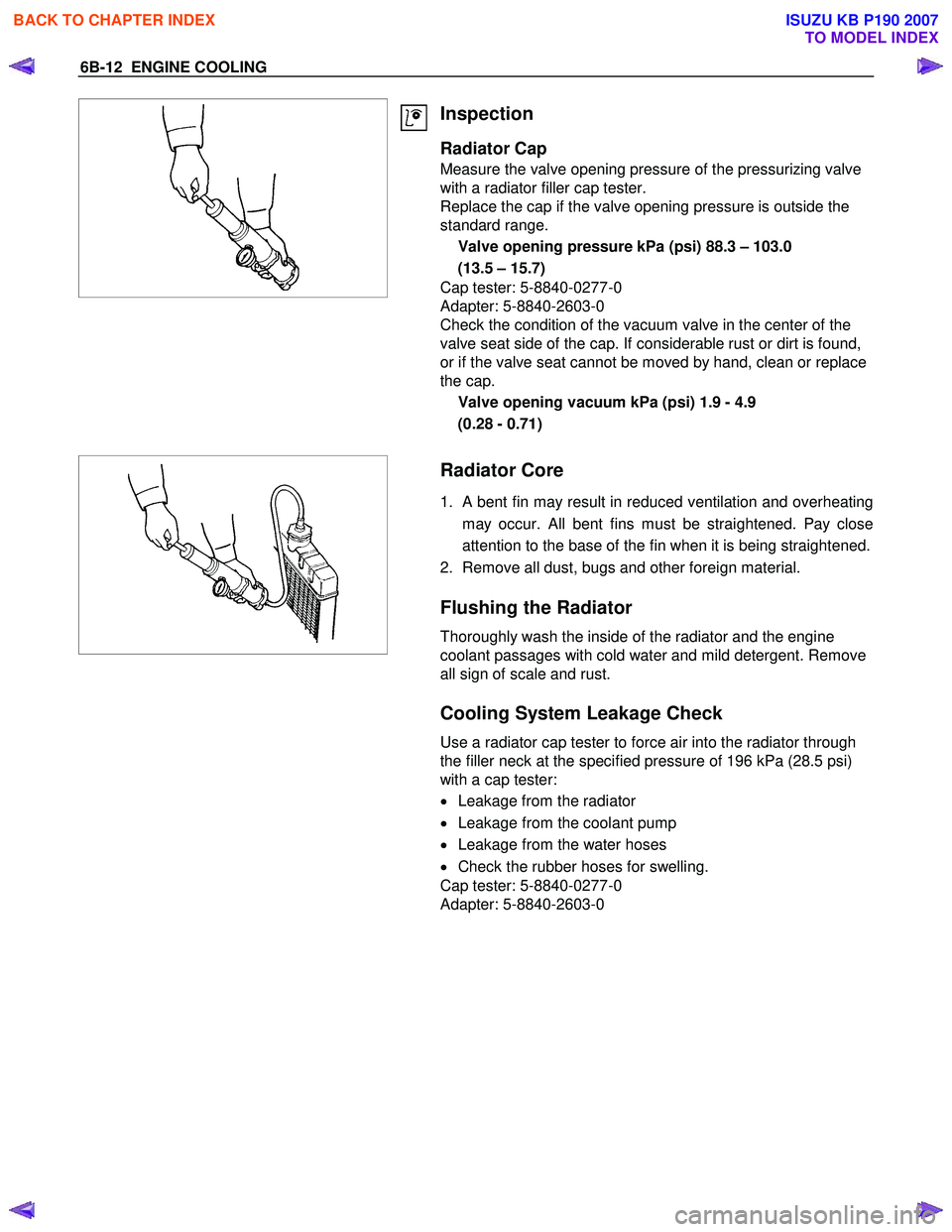
Radiator Cap
Measure the valve opening pressure of the pressurizing valve
with a radiator filler cap tester.
Replace the cap if the valve opening pressure is outside the
standard range.
Valve opening pressure kPa (psi) 88.3 – 103.0
(13.5 – 15.7)
Cap tester: 5-8840-0277-0
Adapter: 5-8840-2603-0
Check the condition of the vacuum valve in the center of the
valve seat side of the cap. If considerable rust or dirt is found,
or if the valve seat cannot be moved by hand, clean or replace
the cap.
Valve opening vacuum kPa (psi) 1.9 - 4.9
(0.28 - 0.71)
Radiator Core
1. A bent fin may result in reduced ventilation and overheating
may occur. All bent fins must be straightened. Pay close
attention to the base of the fin when it is being straightened.
2. Remove all dust, bugs and other foreign material.
Flushing the Radiator
Thoroughly wash the inside of the radiator and the engine
coolant passages with cold water and mild detergent. Remove
all sign of scale and rust.
Cooling System Leakage Check
Use a radiator cap tester to force air into the radiator through
the filler neck at the specified pressure of 196 kPa (28.5 psi)
with a cap tester:
• Leakage from the radiator
• Leakage from the coolant pump
• Leakage from the water hoses
• Check the rubber hoses for swelling.
Cap tester: 5-8840-0277-0
Adapter: 5-8840-2603-0
BACK TO CHAPTER INDEX
TO MODEL INDEX
ISUZU KB P190 2007
Page 2224 of 6020
6E–54 ENGINE DRIVEABILITY AND EMISSIONS
GENERAL DESCRIPTION FOR ELECTRIC
IGNITION SYSTEM
The engine use two ignition coils, one per two cylinders.
A two wire connector provides a battery voltage primary
supply through the ignition fuse.
The ignition control spark timing is the ECM’s method of
controlling the spark advance and the ignition dwell.
The ignition control spark advance and the ignition dwell
are calculated by the ECM using the following inputs.
• Engine speed
• Crankshaft position (CKP) sensor
• Engine coolant temperature (ECT) sensor
• Throttle position sensor
• Vehicle speed sensor
• ECM and ignition system supply voltage
Ignition coil works to generate only the secondary
voltage be receiving the primary voltage from ECM.
The primary voltage is generated at the coil driver
located in the ECM. The coil driver generate the primary
voltage based on the crankshaft position signal. In
accordance with the crankshaft position signal, ignition
coil driver determines the adequate ignition timing and
also cylinder number to ignite.
Ignition timing is determined the coolant temperature,
intake air temperature, engine speed, engine load,
knock sensor signal, etc.
Spark Plug
Although worn or dirty spark plugs may give satisfactory
operation at idling speed, they frequently fail at higher
engine speeds. Faulty spark plugs may cause poor fuel
economy, power loss, loss of speed, hard starting and
generally poor engine performance. Follow the
scheduled maintenance service recommendations to
ensure satisfactory spark plug performance. Refer to
Maintenance and Lubrication .
Normal spark plug operation will result in brown to
grayish-tan deposits appearing on the insulator portion
of the spark plug. A small amount of red-brown, yellow,
and white powdery material may also be present on the
insulator tip around the center electrode. These
deposits are normal combustion by-products of fuels
and lubricating oils with additives. Some electrode wear
will also occur. Engines which are not running properly
are often referred to as “misfiring.” This means the
ignition spark is not igniting the air/fuel mixture at the
proper time. While other ignition and fuel system causes
must also be considered, possible causes include
ignition system conditions which allow the spark voltage
to reach ground in some other manner than by jumping
across the air gap at the tip of the spark plug, leaving
the air/fuel mixture unburned. Misfiring may also occur
when the tip of the spark plug becomes overheated and
ignites the mixture before the spark jumps. This is
referred to as “pre-ignition.”
Spark plugs may also misfire due to fouling, excessive
gap, or a cracked or broken insulator. If misfiring occurs before the recommended replacement interval, locate
and correct the cause.
Carbon fouling of the spark plug is indicated by dry,
black carbon (soot) deposits on the portion of the spark
plug in the cylinder. Excessive idling and slow speeds
under light engine loads can keep the spark plug
temperatures so low that these deposits are not burned
off. Very rich fuel mixtures or poor ignition system output
may also be the cause. Refer to DTC P1167.
Oil fouling of the spark plug is indicated by wet oily
deposits on the portion of the spark plug in the cylinder,
usually with little electrode wear. This may be caused by
oil during break-in of new or newly overhauled engines.
Deposit fouling of the spark plug occurs when the
normal red-brown, yellow or white deposits of
combustion by-products become sufficient to cause
misfiring. In some cases, these deposits may melt and
form a shiny glaze on the insulator around the center
electrode. If the fouling is found in only one or two
cylinders, valve stem clearances or intake valve seals
may be allowing excess lubricating oil to enter the
cylinder, particularly if the deposits are heavier on the
side of the spark plug facing the intake valve.
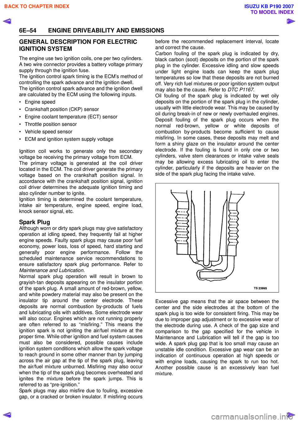
Excessive gap means that the air space between the
center and the side electrodes at the bottom of the
spark plug is too wide for consistent firing. This may be
due to improper gap adjustment or to excessive wear of
the electrode during use. A check of the gap size and
comparison to the gap specified for the vehicle in
Maintenance and Lubrication will tell if the gap is too
wide. A spark plug gap that is too small may cause an
unstable idle condition. Excessive gap wear can be an
indication of continuous operation at high speeds or
with engine loads, causing the spark to run too hot.
Another possible cause is an excessively lean fuel
mixture.
BACK TO CHAPTER INDEX
TO MODEL INDEX
ISUZU KB P190 2007
Page 2235 of 6020
ENGINE DRIVEABILITY AND EMISSIONS 6E–65
Step 3: Simulate the symptom and isolate the
problem
Simulate the symptom and isolate the system by
reproducing all possible conditions suggested in Step 1
while monitoring suspected circuits/components/
systems to isolate the problem symptom. Begin with the
most logical circuit/component.
Isolate the circuit by dividing the suspect system into
simpler circuits. Next, confine the problem into a smaller
area of the system. Begin at the most logical point (or
point of easiest access) and thoroughly check the
isolated circuit for the fault, using basic circuit tests.
Hints
You can isolate a circuit by:
• Unplugging connectors or removing a fuse to separate one part of the circuit from another
• If only component fails to operate, begin testing the component
• If a number of components do not operate, begin test at areas of commonality (such as power sources,
ground circuits, switches, main connectors or major
components)
• Substitute a known good part from the parts department or the vehicle system
• Try the suspect part in a known good vehicle
See Symptom Simulation Tests on the next page for
problem simulation procedures. Refer to service manual
sections 6E and 8A for information about intermittent
diagnosis. Follow procedures for basic circuit testing in
service manual section 8A.
What resources you should use
Whenever appropriate, you should use the following
resources to assist in the diagnostic process:
• Service manual
• Bulletins
• Digital multimeter (with a MIN/MAX feature)
• Tech II and Tech II upload function
• Circuit testing tools (including connector kits/ harnesses and jumper wires)
• Experience
• Intermittent problem solving simulation methods
• Customer complaint check sheet
Symptom Simulation Tests
1. Vibration
This method is useful when the customer complaint
analysis indicates that the problem occurs when the
vehicle/system undergoes some form of vibration.
For connectors and wire harness, slightly shake
vertically and horizontally. Inspect the connector joint
and body for damage. Also, tapping lightly along a
suspected circuit may be helpful. For parts and sensors, apply slight vibration to the part
with a light tap of the finger while monitoring the system
for a malfunction.
2. Heat
This method is important when the complaint suggests
that the problem occurs in a heated environment. Apply
moderate heat to the component with a hair drier or
similar tool while monitoring the system for a
malfunction.
CAUTION: Care must be take to avoid overheating
the component.
3. Water and Moisture
This method may be used when the complaint suggests
that the malfunction occurs on a rainy day or under
conditions of high humidity. In this case, apply water in a
light spray on the vehicle to duplicate the problem.
CAUTION: Care must be take to avoid directly
exposing electrical connections to water.
4. Electrical loads
This method involves turning systems ON (such as the
blower, lights or rear window defogger) to create a load
on the vehicle electrical system at the same time you
are monitoring the suspect circuit/component.
5e. Vehicle Operates as Designed
This condition refers to instances where a system
operating as designed is perceived to be unsatisfactory
or undesirable. In general, this is due to:
• A lack of understanding by the customer
• A conflict between customer expectations and vehicle design intent
• A system performance that is unacceptable to the customer
What you should do
You can verify that a system is operating as designed
by:
• Reviewing service manual functional/diagnostic checks
• Examining bulletins and other service information for supplementary information
• Compare system operation to an identical vehicle
If the condition is due to a customer misunderstanding
or a conflict between customer expectation and system
operation, you should explain the system operation to
the customer.
If the complaint is due to a case of unsatisfactory
system performance, you should contact Technical
Assistance for the latest information.
What resources you should use
Whenever possible, you should use the following
resources to facilitate the diagnostic process:
BACK TO CHAPTER INDEX
TO MODEL INDEX
ISUZU KB P190 2007
Page 2424 of 6020
6E–254 ENGINE DRIVEABILITY AND EMISSIONS
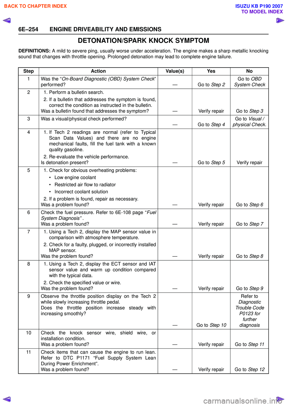
DETONATION/SPARK KNOCK SYMPTOM
DEFINITIONS: A mild to severe ping, usually worse under acceleration. The engine makes a sharp metallic knocking
sound that changes with throttle opening. Prolonged detonation may lead to complete engine tailure.
Step Action Value(s) Yes No
1 Was the “ On-Board Diagnostic (OBD) System Check ”
performed? — Go to Step 2Go to
OBD
System Check
2 1. Perform a bulletin search. 2. If a bulletin that addresses the symptom is found,correct the condition as instructed in the bulletin.
Was a bulletin found that addresses the symptom? — Verify repair Go to Step 3
3 Was a visual/physical check performed? —Go to Step 4Go to
Visual /
physical Check .
4 1. If Tech 2 readings are normal (refer to Typical Scan Data Values) and there are no engine
mechanical faults, fill the fuel tank with a known
quality gasoline.
2. Re-evaluate the vehicle performance.
Is detonation present? — Go to Step 5Verify repair
5 1. Check for obvious overheating problems: • Low engine coolant
• Restricted air flow to radiator
• Incorrect coolant solution
2. If a problem is found, repair as necessary.
Was a problem found? — Verify repair Go to Step 6
6 Check the fuel pressure. Refer to 6E-108 page “ Fuel
System Diagnosis” .
Was a problem found? — Verify repair Go to Step 7
7 1. Using a Tech 2, display the MAP sensor value in comparison with atmosphere temperature.
2. Check for a faulty, plugged, or incorrectly installed MAP sensor.
Was the problem found? — Verify repair Go to Step 8
8 1. Using a Tech 2, display the ECT sensor and IAT sensor value and warm up condition compared
with the typical data.
2. Check the specified value or wire.
Was the problem found? — Verify repair Go to Step 9
9 Observe the throttle position display on the Tech 2 while slowly increasing throttle pedal.
Does the throttle position increase steady with
increasing smoothly?
—Go to Step 10Refer to
Diagnostic
Trouble Code P0123 for further
diagnosis
10 Check the knock sensor wire, shield wire, or installation condition.
Was a problem found? — Verify repair Go to Step 11
11 Check items that can cause the engine to run lean. Refer to DTC P1171 “Fuel Supply System Lean
During Power Enrichment”.
Was a problem found? — Verify repair Go to Step 12
BACK TO CHAPTER INDEX
TO MODEL INDEX
ISUZU KB P190 2007
Page 2452 of 6020
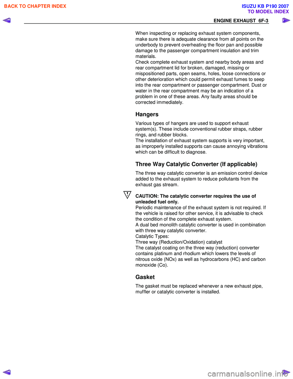
ENGINE EXHAUST 6F-3
W hen inspecting or replacing exhaust system components,
make sure there is adequate clearance from all points on the
underbody to prevent overheating the floor pan and possible
damage to the passenger compartment insulation and trim
materials.
Check complete exhaust system and nearby body areas and
rear compartment lid for broken, damaged, missing or
mispositioned parts, open seams, holes, loose connections or
other deterioration which could permit exhaust fumes to seep
into the rear compartment or passenger compartment. Dust or
water in the rear compartment may be an indication of a
problem in one of these areas. Any faulty areas should be
corrected immediately.
Hangers
Various types of hangers are used to support exhaust
system(s). These include conventional rubber straps, rubber
rings, and rubber blocks.
The installation of exhaust system supports is very important,
as improperly installed supports can cause annoying vibrations
which can be difficult to diagnose.
Three Way Catalytic Converter (If applicable)
The three way catalytic converter is an emission control device
added to the exhaust system to reduce pollutants from the
exhaust gas stream.
CAUTION: The catalytic converter requires the use of
unleaded fuel only.
Periodic maintenance of the exhaust system is not required. If
the vehicle is raised for other service, it is advisable to check
the condition of the complete exhaust system.
A dual bed monolith catalytic converter is used in combination
with three way catalytic converter.
Catalytic Types:
Three way (Reduction/Oxidation) catalyst
The catalyst coating on the three way (reduction) converter
contains platinum and rhodium which lowers the levels of
nitrous oxide (NOx) as well as hydrocarbons (HC) and carbon
monoxide (Co).
Gasket
The gasket must be replaced whenever a new exhaust pipe,
muffler or catalytic converter is installed.
BACK TO CHAPTER INDEX
TO MODEL INDEX
ISUZU KB P190 2007
Page 2509 of 6020
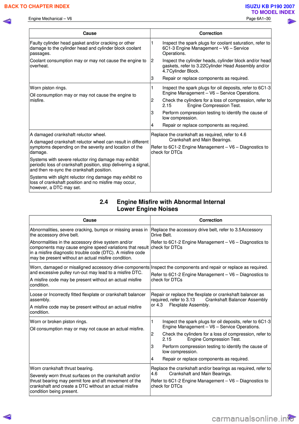
Engine Mechanical – V6 Page 6A1–30
Cause Correction
Faulty cylinder head gasket and/or cracking or other
damage to the cylinder head and cylinder block coolant
passages.
Coolant consumption may or may not cause the engine to
overheat. 1 Inspect the spark plugs for coolant saturation, refer to
6C1-3 Engine Management – V6 – Service
Operations.
2 Inspect the cylinder heads, cylinder block and/or head gaskets, refer to 3.22 Cylinder Head Assembly and/or
4.7 Cylinder Block.
3 Repair or replace components as required.
W orn piston rings.
Oil consumption may or may not cause the engine to
misfire. 1 Inspect the spark plugs for oil deposits, refer to 6C1-3
Engine Management – V6 – Service Operations.
2 Check the cylinders for a loss of compression, refer to 2.15 Engine Compression Test.
3 Perform compression testing to identify the cause of low compression.
4 Repair or replace components as required.
A damaged crankshaft reluctor wheel.
A damaged crankshaft reluctor wheel can result in different
symptoms depending on the severity and location of the
damage.
Systems with severe reluctor ring damage may exhibit
periodic loss of crankshaft position, stop delivering a signal,
and then re-sync the crankshaft position.
Systems with slight reluctor ring damage may exhibit no
loss of crankshaft position and no misfire may occur,
however, a DTC may set. Replace the crankshaft as required, refer to 4.6
Crankshaft and Main Bearings.
Refer to 6C1-2 Engine Management – V6 – Diagnostics to
check for DTCs
2.4 Engine Misfire with Abnormal Internal Lower Engine Noises
Cause Correction
Abnormalities, severe cracking, bumps or missing areas in
the accessory drive belt.
Abnormalities in the accessory drive system and/or
components may cause engine speed variations that result
in a misfire diagnostic trouble code (DTC). A misfire code
may be present without an actual misfire condition. Replace the accessory drive belt, refer to 3.5
Accessory
Drive Belt.
Refer to 6C1-2 Engine Management – V6 – Diagnostics to
check for DTCs
W orn, damaged or misaligned accessory drive components
and excessive pulley run-out may lead to a misfire DTC.
A misfire code may be present without an actual misfire
condition. Inspect the components and repair or replace as required.
Refer to 6C1-2 Engine Management – V6 – Diagnostics to
check for DTCs
Loose or Incorrectly fitted flexplate or crankshaft balancer
assembly.
A misfire code may be present without an actual misfire
condition. Repair or replace the flexplate or crankshaft balancer as
required, refer to 3.13 Crankshaft Balancer Assembly
or 4.3 Flexplate Assembly.
W orn or broken piston rings.
Oil consumption may or may not cause an actual misfire. 1 Inspect the spark plugs for oil deposits, refer to 6C1-3
Engine Management – V6 – Service Operations.
2 Check the cylinders for a loss of compression, refer to 2.15 Engine Compression Test.
3 Perform compression testing to identify the cause of low compression.
4 Repair or replace components as required.
W orn crankshaft thrust bearing.
Severely worn thrust surfaces on the crankshaft and/or
thrust bearing may permit fore and aft movement of the
crankshaft and create a DTC without an actual misfire
condition being present. Replace the crankshaft and/or bearings as required, refer to
4.6 Crankshaft and Main Bearings.
Refer to 6C1-2 Engine Management – V6 – Diagnostics to
check for DTCs
BACK TO CHAPTER INDEX
TO MODEL INDEX
ISUZU KB P190 2007
Page 2510 of 6020
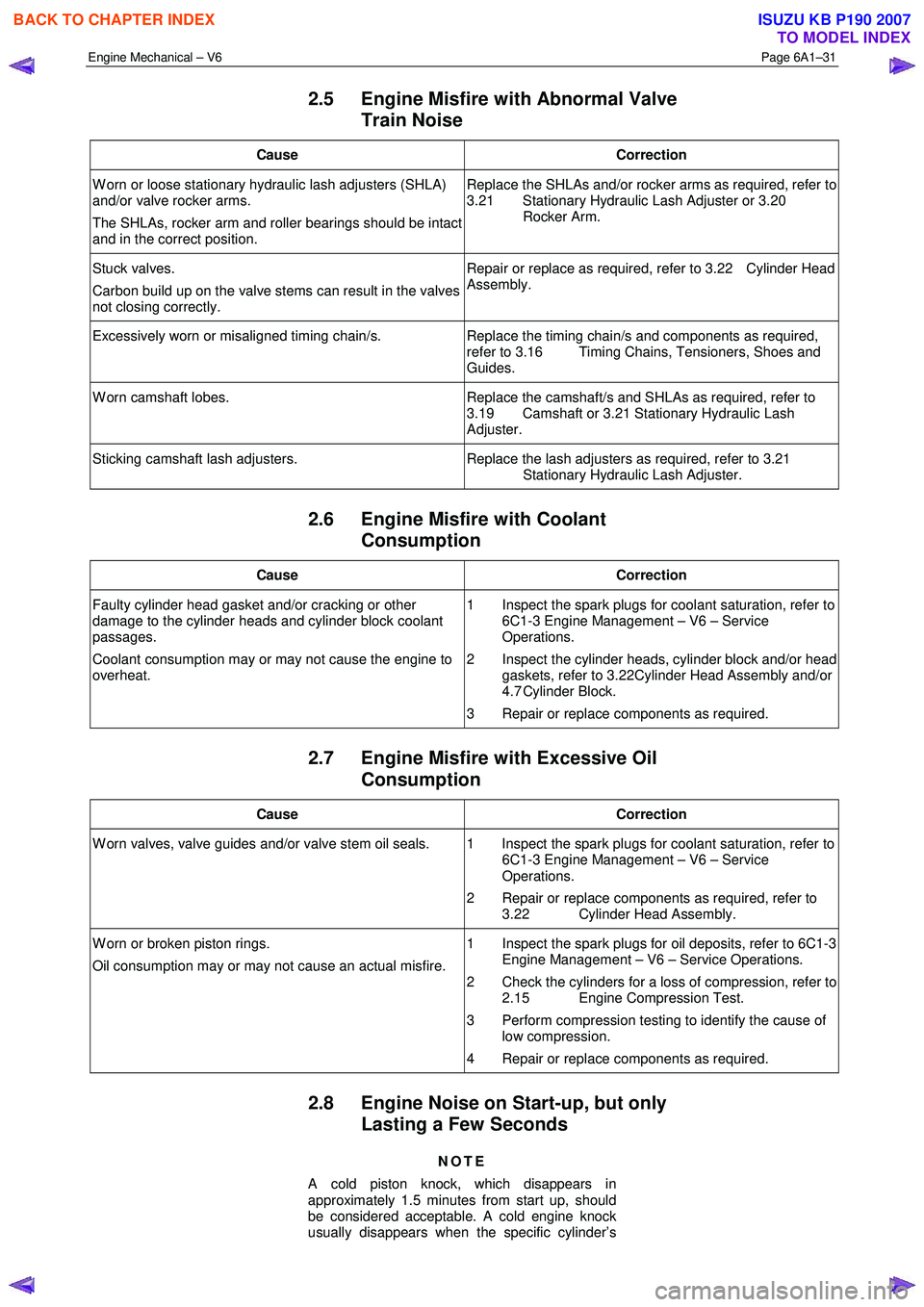
Engine Mechanical – V6 Page 6A1–31
2.5 Engine Misfire with Abnormal Valve
Train Noise
Cause Correction
W orn or loose stationary hydraulic lash adjusters (SHLA)
and/or valve rocker arms.
The SHLAs, rocker arm and roller bearings should be intact
and in the correct position. Replace the SHLAs and/or rocker arms as required, refer to
3.21 Stationary Hydraulic Lash Adjuster or 3.20
Rocker Arm.
Stuck valves.
Carbon build up on the valve stems can result in the valves
not closing correctly. Repair or replace as required, refer to 3.22 Cylinder Head
Assembly.
Excessively worn or misaligned timing chain/s. Replace the timing chain/s and components as required,
refer to 3.16 Timing Chains, Tensioners, Shoes and
Guides.
W orn camshaft lobes. Replace the camshaft/s and SHLAs as required, refer to
3.19 Camshaft or 3.21 Stationary Hydraulic Lash
Adjuster.
Sticking camshaft lash adjusters. Replace the lash adjusters as required, refer to 3.21
Stationary Hydraulic Lash Adjuster.
2.6 Engine Misfire with Coolant
Consumption
Cause Correction
Faulty cylinder head gasket and/or cracking or other
damage to the cylinder heads and cylinder block coolant
passages.
Coolant consumption may or may not cause the engine to
overheat. 1 Inspect the spark plugs for coolant saturation, refer to
6C1-3 Engine Management – V6 – Service
Operations.
2 Inspect the cylinder heads, cylinder block and/or head gaskets, refer to 3.22 Cylinder Head Assembly and/or
4.7 Cylinder Block.
3 Repair or replace components as required.
2.7 Engine Misfire with Excessive Oil Consumption
Cause Correction
W orn valves, valve guides and/or valve stem oil seals. 1 Inspect the spark plugs for coolant saturation, refer to 6C1-3 Engine Management – V6 – Service
Operations.
2 Repair or replace components as required, refer to 3.22 Cylinder Head Assembly.
W orn or broken piston rings.
Oil consumption may or may not cause an actual misfire. 1 Inspect the spark plugs for oil deposits, refer to 6C1-3
Engine Management – V6 – Service Operations.
2 Check the cylinders for a loss of compression, refer to 2.15 Engine Compression Test.
3 Perform compression testing to identify the cause of low compression.
4 Repair or replace components as required.
2.8 Engine Noise on Start-up, but only Lasting a Few Seconds
NOTE
A cold piston knock, which disappears in
approximately 1.5 minutes from start up, should
be considered acceptable. A cold engine knock
usually disappears when the specific cylinder’s
BACK TO CHAPTER INDEX
TO MODEL INDEX
ISUZU KB P190 2007