2007 ISUZU KB P190 belt
[x] Cancel search: beltPage 1578 of 6020

FUEL SYSTEM (4JK1/4JJ1) 6C-37
24. Install the A/C compressor.
RTW 56ASH004201
Legend
1. A/C Compressor Bracket
2. Intake Duct
3. A/C Compressor
Tighten the bolts to the specified torque.
Tightening torque: 44 N ⋅
⋅⋅
⋅
m (4.5 kg ⋅
⋅⋅
⋅
m / 33 lb ft)
25. Install the battery.
26. Install the A/C compressor adjust pulley.
RTW 56ASH010601
Legend
1. Bolt
2. Nut
Tighten the nut and bolt to the specified torque.
Bolt Tightening torque: 25 N ⋅
⋅⋅
⋅
m (2.5 kg ⋅
⋅⋅
⋅
m/18 lb ft)
Nut Tightening torque: 25 N ⋅
⋅⋅
⋅
m (2.5 kg ⋅
⋅⋅
⋅
m/18 lb ft)
27. Install the A/C compressor drive belt.
Refer to the drive belt tension check procedure fo
r
Heating and air conditioning in this manual.
28. Install the cooling fan.
29. Install the fan guide.
30. Install the radiator upper hose.
31. Replenish the engine coolant.
Fuel Supply Pump Relearn Procedure
The ECM goes through a fuel supply pump learn
procedure to fine tune the current supplied to the fuel
rail pressure (FRP) regulator. This learning process in
only performed when the engine is idling.
1. Install the scan tool.
2. Turn ON the ignition, with the engine OFF.
3. Command the Supply Pump Learn Reset with the scan tool.
4. Observe the Supply Pump Status parameter with the scan tool. Confirm the scan tool indicates Not
Learn.
5. Start the engine and let idle until engine coolant temperature (ECT) reads 149°F (65°C) or highe
r
while observing Supply Pump Status parameter
with the scant tool. The scan tool changes status
Not Learn > Learning > Learned.
6. If the ECM has correctly learned the fuel supply pump current adjustment, the Supply Pump Status
parameter on the scan tool will repeatedly indicate
Learning and Learned.
BACK TO CHAPTER INDEX
TO MODEL INDEX
ISUZU KB P190 2007
Page 1590 of 6020
6D-2 ENGINE ELECTRICAL (4JK1/4JJ1)
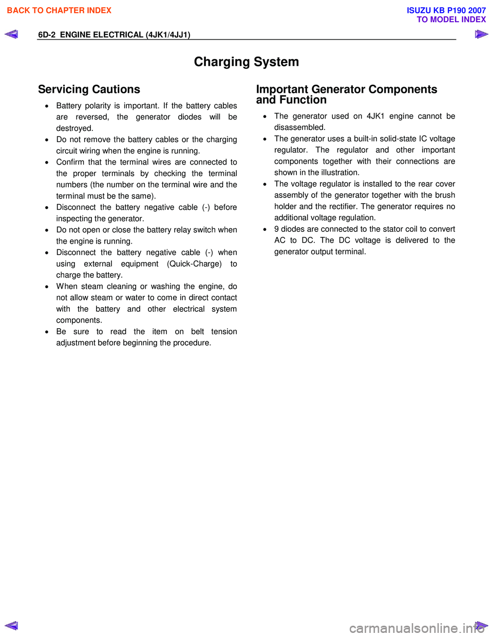
Charging System
Servicing Cautions
• Battery polarity is important. If the battery cables
are reversed, the generator diodes will be
destroyed.
• Do not remove the battery cables or the charging
circuit wiring when the engine is running.
• Confirm that the terminal wires are connected to
the proper terminals by checking the terminal
numbers (the number on the terminal wire and the
terminal must be the same).
• Disconnect the battery negative cable (-) before
inspecting the generator.
• Do not open or close the battery relay switch when
the engine is running.
• Disconnect the battery negative cable (-) when
using external equipment (Quick-Charge) to
charge the battery.
• W hen steam cleaning or washing the engine, do
not allow steam or water to come in direct contact
with the battery and other electrical system
components.
• Be sure to read the item on belt tension
adjustment before beginning the procedure.
Important Generator Components
and Function
• The generator used on 4JK1 engine cannot be
disassembled.
• The generator uses a built-in solid-state IC voltage
regulator. The regulator and other important
components together with their connections are
shown in the illustration.
• The voltage regulator is installed to the rear cove
r
assembly of the generator together with the brush
holder and the rectifier. The generator requires no
additional voltage regulation.
• 9 diodes are connected to the stator coil to convert
AC to DC. The DC voltage is delivered to the
generator output terminal.
BACK TO CHAPTER INDEX
TO MODEL INDEX
ISUZU KB P190 2007
Page 1594 of 6020
6D-6 ENGINE ELECTRICAL (4JK1/4JJ1)
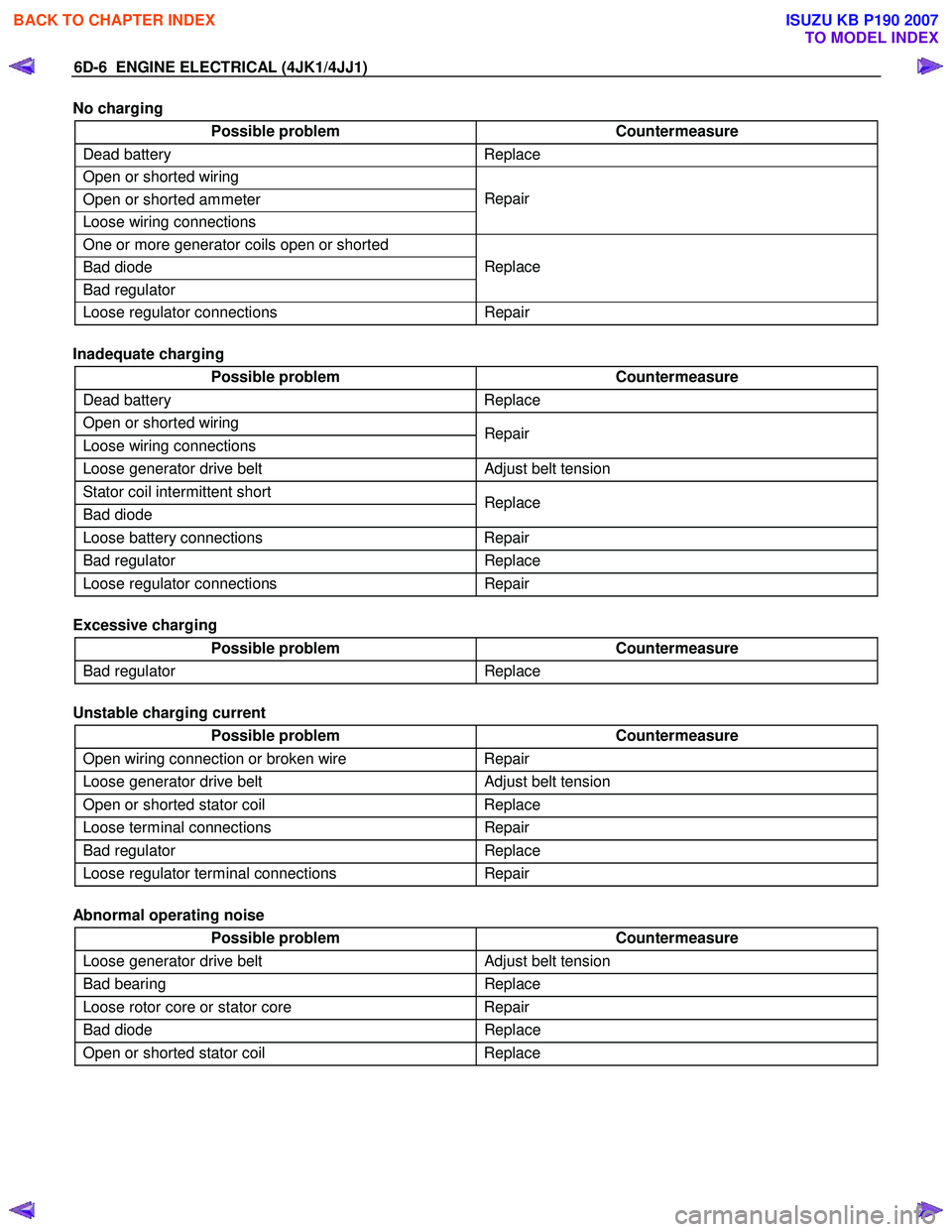
No charging
Possible problem Countermeasure
Dead battery Replace
Open or shorted wiring
Open or shorted ammeter
Loose wiring connections Repair
One or more generator coils open or shorted
Bad diode
Bad regulator Replace
Loose regulator connections
Repair
Inadequate charging
Possible problem Countermeasure
Dead battery Replace
Open or shorted wiring
Loose wiring connections Repair
Loose generator drive belt
Adjust belt tension
Stator coil intermittent short
Bad diode Replace
Loose battery connections
Repair
Bad regulator Replace
Loose regulator connections Repair
Excessive charging
Possible problem Countermeasure
Bad regulator Replace
Unstable charging current
Possible problem Countermeasure
Open wiring connection or broken wire Repair
Loose generator drive belt Adjust belt tension
Open or shorted stator coil Replace
Loose terminal connections Repair
Bad regulator Replace
Loose regulator terminal connections Repair
Abnormal operating noise
Possible problem Countermeasure
Loose generator drive belt Adjust belt tension
Bad bearing Replace
Loose rotor core or stator core Repair
Bad diode Replace
Open or shorted stator coil Replace
BACK TO CHAPTER INDEX
TO MODEL INDEX
ISUZU KB P190 2007
Page 1595 of 6020
ENGINE ELECTRICAL (4JK1/4JJ1) 6D-7
Diagnosis
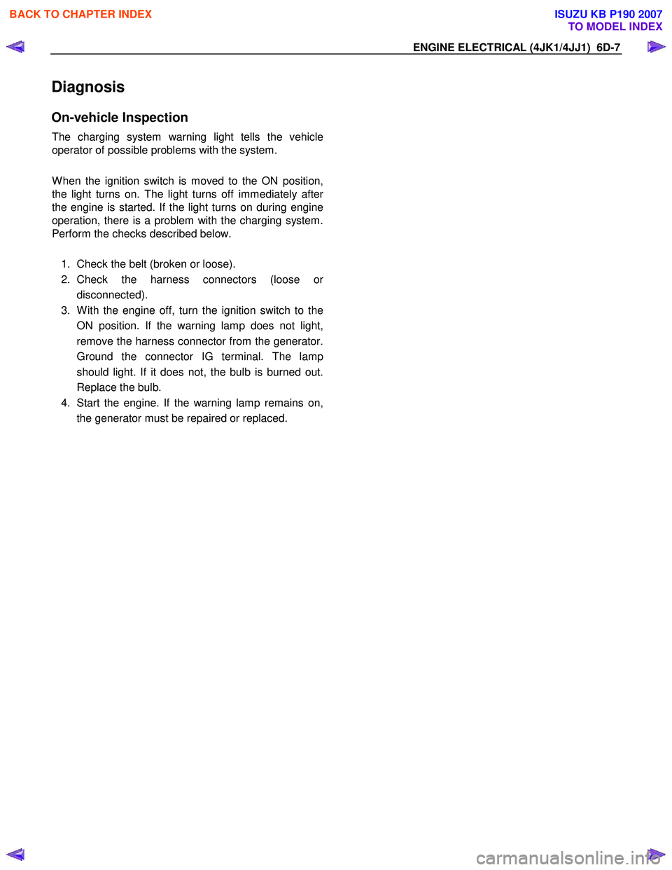
On-vehicle Inspection
The charging system warning light tells the vehicle
operator of possible problems with the system.
W hen the ignition switch is moved to the ON position,
the light turns on. The light turns off immediately afte
r
the engine is started. If the light turns on during engine
operation, there is a problem with the charging system.
Perform the checks described below.
1. Check the belt (broken or loose).
2. Check the harness connectors (loose o
r
disconnected).
3. W ith the engine off, turn the ignition switch to the ON position. If the warning lamp does not light,
remove the harness connector from the generator.
Ground the connector IG terminal. The lamp
should light. If it does not, the bulb is burned out.
Replace the bulb.
4. Start the engine. If the warning lamp remains on, the generator must be repaired or replaced.
BACK TO CHAPTER INDEX
TO MODEL INDEX
ISUZU KB P190 2007
Page 1752 of 6020
ENGINE CONTROL SYSTEM (4JK1/4JJ1) 6E-135
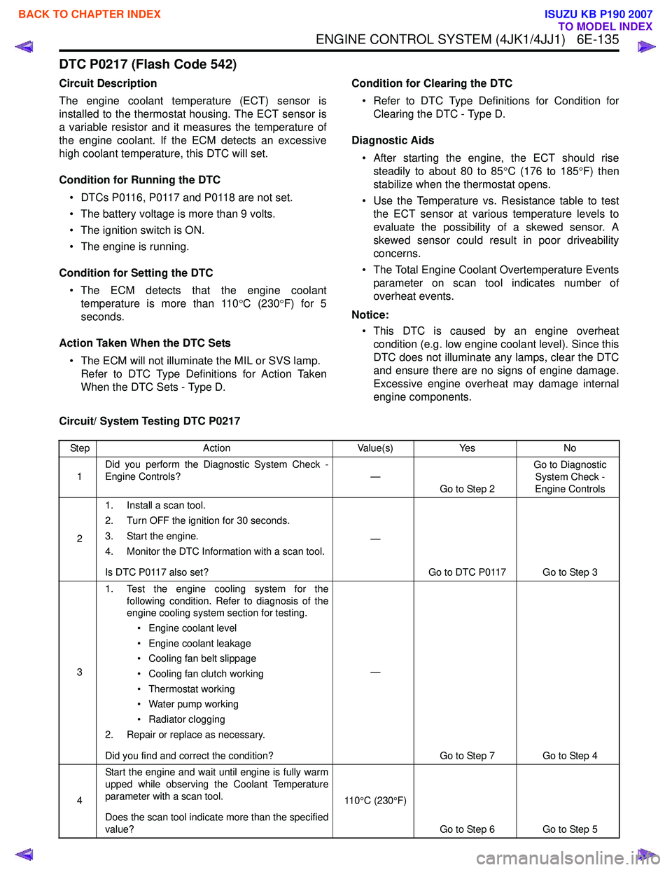
DTC P0217 (Flash Code 542)
Circuit Description
The engine coolant temperature (ECT) sensor is
installed to the thermostat housing. The ECT sensor is
a variable resistor and it measures the temperature of
the engine coolant. If the ECM detects an excessive
high coolant temperature, this DTC will set.
Condition for Running the DTC • DTCs P0116, P0117 and P0118 are not set.
• The battery voltage is more than 9 volts.
• The ignition switch is ON.
• The engine is running.
Condition for Setting the DTC • The ECM detects that the engine coolant temperature is more than 110 °C (230 °F) for 5
seconds.
Action Taken When the DTC Sets • The ECM will not illuminate the MIL or SVS lamp. Refer to DTC Type Definitions for Action Taken
When the DTC Sets - Type D. Condition for Clearing the DTC
• Refer to DTC Type Definitions for Condition for Clearing the DTC - Type D.
Diagnostic Aids • After starting the engine, the ECT should rise steadily to about 80 to 85 °C (176 to 185 °F) then
stabilize when the thermostat opens.
• Use the Temperature vs. Resistance table to test the ECT sensor at various temperature levels to
evaluate the possibility of a skewed sensor. A
skewed sensor could result in poor driveability
concerns.
• The Total Engine Coolant Overtemperature Events parameter on scan tool indicates number of
overheat events.
Notice: • This DTC is caused by an engine overheat condition (e.g. low engine coolant level). Since this
DTC does not illuminate any lamps, clear the DTC
and ensure there are no signs of engine damage.
Excessive engine overheat may damage internal
engine components.
Circuit/ System Testing DTC P0217
Step Action Value(s)Yes No
1 Did you perform the Diagnostic System Check -
Engine Controls? —
Go to Step 2 Go to Diagnostic
System Check -
Engine Controls
2 1. Install a scan tool.
2. Turn OFF the ignition for 30 seconds.
3. Start the engine.
4. Monitor the DTC Information with a scan tool.
Is DTC P0117 also set? —
Go to DTC P0117 Go to Step 3
3 1. Test the engine cooling system for the
following condition. Refer to diagnosis of the
engine cooling system section for testing.
• Engine coolant level
• Engine coolant leakage
• Cooling fan belt slippage
• Cooling fan clutch working
• Thermostat working
• Water pump working
• Radiator clogging
2. Repair or replace as necessary.
Did you find and correct the condition? —
Go to Step 7 Go to Step 4
4 Start the engine and wait until engine is fully warm
upped while observing the Coolant Temperature
parameter with a scan tool.
Does the scan tool indicate more than the specified
value? 11 0
°C (230 °F)
Go to Step 6 Go to Step 5
BACK TO CHAPTER INDEX
TO MODEL INDEX
ISUZU KB P190 2007
Page 1958 of 6020
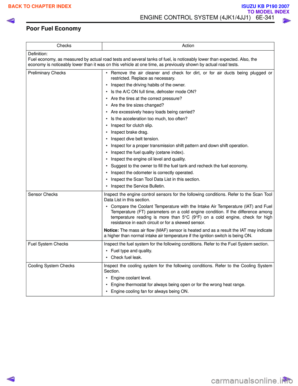
ENGINE CONTROL SYSTEM (4JK1/4JJ1) 6E-341
Poor Fuel Economy
ChecksAction
Definition:
Fuel economy, as measured by actual road tests and several tanks of fuel, is noticeably lower than expected. Also, the
economy is noticeably lower than it was on this vehicle at one time, as previously shown by actual road tests.
Preliminary Checks • Remove the air cleaner and check for dirt, or for air ducts being plugged or
restricted. Replace as necessary.
• Inspect the driving habits of the owner.
• Is the A/C ON full time, defroster mode ON?
• Are the tires at the correct pressure?
• Are the tire sizes changed?
• Are excessively heavy loads being carried?
• Is the acceleration too much, too often?
• Inspect for clutch slip.
• Inspect brake drag.
• Inspect dive belt tension.
• Inspect for a proper transmission shift pattern and down shift operation.
• Inspect the fuel quality (cetane index).
• Inspect the engine oil level and quality.
• Suggest to the owner to fill the fuel tank and recheck the fuel economy.
• Inspect the odometer is correctly operated.
• Inspect the Scan Tool Data List in this section.
• Inspect the Service Bulletin.
Sensor Checks Inspect the engine control sensors for the following conditions. Refer to the Scan Tool
Data List in this section.
• Compare the Coolant Temperature with the Intake Air Temperature (IAT) and Fuel Temperature (FT) parameters on a cold engine condition. If the difference among
temperature reading is more than 5 °C (9 °F) on a cold engine, check for high
resistance in each circuit or for a skewed sensor.
Notice: The mass air flow (MAF) sensor is heated and as a result the IAT may indicate
a higher than normal intake air temperature if the ignition switch is being ON.
Fuel System Checks Inspect the fuel system for the following conditions. Refer to the Fuel System section.
• Fuel type and quality.
• Check fuel leak.
Cooling System Checks Inspect the cooling system for the following conditions. Refer to the Cooling System
Section.
• Engine coolant level.
• Engine thermostat for always being open or for the wrong heat range.
• Engine cooling fan for always being ON.
BACK TO CHAPTER INDEX
TO MODEL INDEX
ISUZU KB P190 2007
Page 2008 of 6020
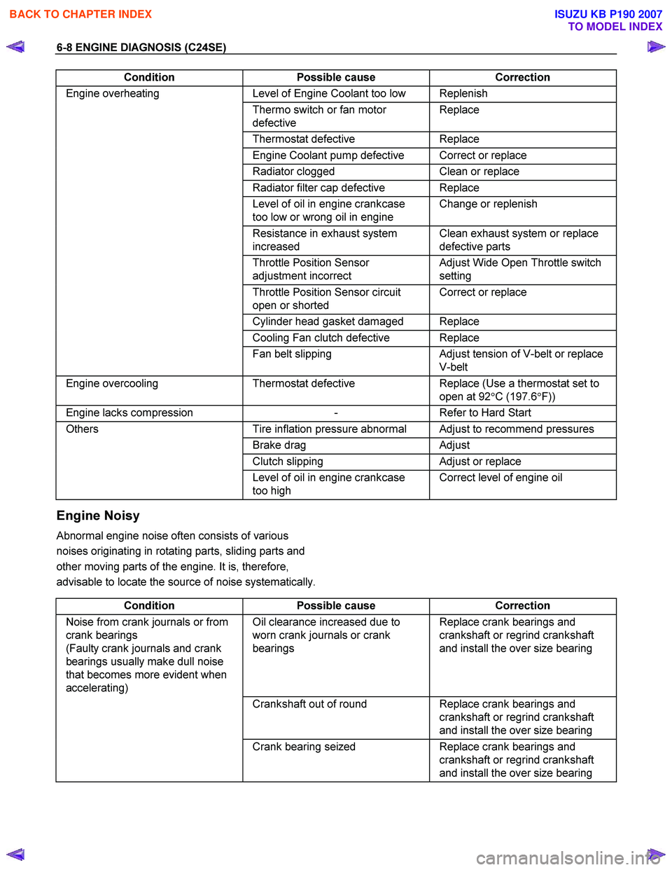
6-8 ENGINE DIAGNOSIS (C24SE)
Condition Possible cause Correction
Engine overheating Level of Engine Coolant too low Replenish
Thermo switch or fan motor
defective Replace
Thermostat
defective Replace
Engine Coolant pump defective Correct or replace
Radiator clogged Clean or replace
Radiator filter cap defective Replace
Level of oil in engine crankcase
too low or wrong oil in engine Change or replenish
Resistance in exhaust system
increased Clean exhaust system or replace
defective parts
Throttle Position Sensor
adjustment incorrect Adjust Wide Open Throttle switch
setting
Throttle Position Sensor circuit
open or shorted Correct or replace
Cylinder head gasket damaged Replace
Cooling Fan clutch defective Replace
Fan belt slipping Adjust tension of V-belt or replace
V-belt
Engine overcooling Thermostat defective Replace (Use a thermostat set to
open at 92 °C (197.6 °F))
Engine lacks compression - Refer to Hard Start
Others Tire inflation pressure abnormal Adjust to recommend pressures
Brake drag Adjust
Clutch slipping Adjust or replace
Level of oil in engine crankcase
too high Correct level of engine oil
Engine Noisy
Abnormal engine noise often consists of various
noises originating in rotating parts, sliding parts and
other moving parts of the engine. It is, therefore,
advisable to locate the source of noise systematically.
Condition Possible cause Correction
Noise from crank journals or from
crank bearings
(Faulty crank journals and crank
bearings usually make dull noise
that becomes more evident when
accelerating) Oil clearance increased due to
worn crank journals or crank
bearings Replace crank bearings and
crankshaft or regrind crankshaft
and install the over size bearing
Crankshaft out of round Replace crank bearings and
crankshaft or regrind crankshaft
and install the over size bearing
Crank bearing seized Replace crank bearings and
crankshaft or regrind crankshaft
and install the over size bearing
BACK TO CHAPTER INDEX
TO MODEL INDEX
ISUZU KB P190 2007
Page 2010 of 6020
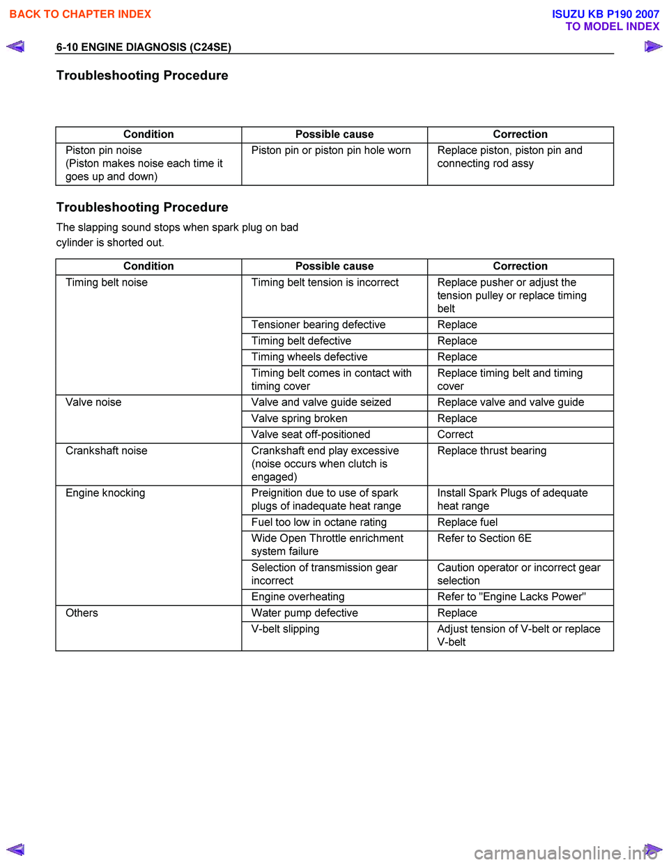
6-10 ENGINE DIAGNOSIS (C24SE)
Troubleshooting Procedure
Condition Possible cause Correction
Piston pin noise
(Piston makes noise each time it
goes up and down) Piston pin or piston pin hole worn Replace piston, piston pin and
connecting rod assy
Troubleshooting Procedure
The slapping sound stops when spark plug on bad
cylinder is shorted out.
Condition Possible cause Correction
Timing belt noise Timing belt tension is incorrect Replace pusher or adjust the
tension pulley or replace timing
belt
Tensioner bearing defective Replace
Timing belt defective Replace
Timing wheels defective Replace
Timing belt comes in contact with
timing cover Replace timing belt and timing
cover
Valve noise Valve and valve guide seized Replace valve and valve guide
Valve spring broken Replace
Valve seat off-positioned Correct
Crankshaft noise Crankshaft end play excessive
(noise occurs when clutch is
engaged) Replace thrust bearing
Engine knocking
Preignition due to use of spark
plugs of inadequate heat range Install Spark Plugs of adequate
heat range
Fuel too low in octane rating Replace fuel
Wide Open Throttle enrichment
system failure Refer to Section 6E
Selection of transmission gear
incorrect Caution operator or incorrect gear
selection
Engine overheating Refer to "Engine Lacks Power"
Others Water pump defective Replace
V-belt slipping Adjust tension of V-belt or replace
V-belt
BACK TO CHAPTER INDEX
TO MODEL INDEX
ISUZU KB P190 2007