Page 1458 of 6020
6A-98 ENGINE MECHANICAL (4JK1/4JJ1)
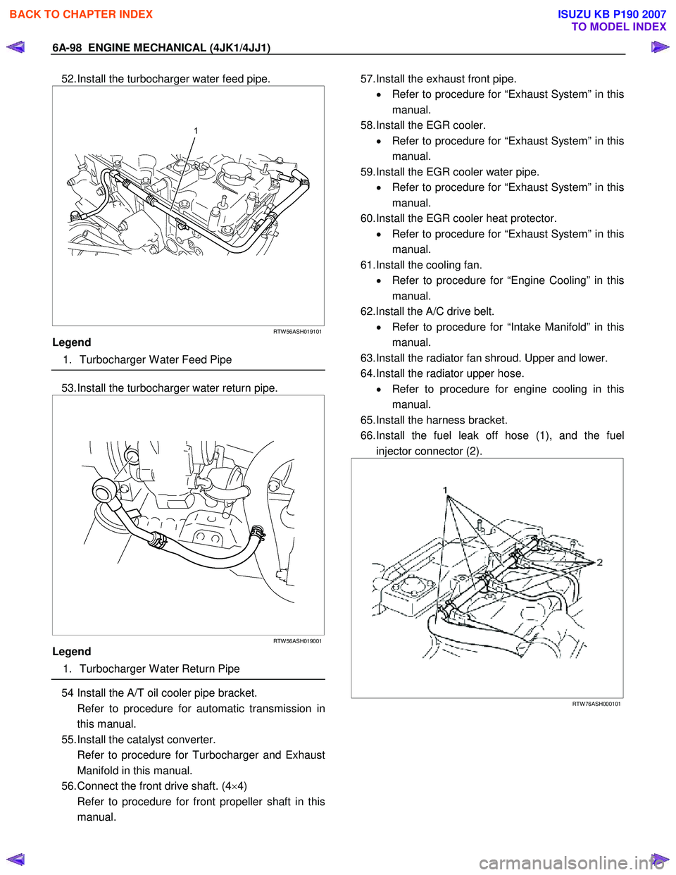
52. Install the turbocharger water feed pipe.
RTW 56ASH019101
Legend
1. Turbocharger W ater Feed Pipe
53. Install the turbocharger water return pipe.
RTW 56ASH019001
Legend
1. Turbocharger W ater Return Pipe
54 Install the A/T oil cooler pipe bracket.
Refer to procedure for automatic transmission in this manual.
55. Install the catalyst converter.
Refer to procedure for Turbocharger and Exhaust Manifold in this manual.
56. Connect the front drive shaft. (4 ×4)
Refer to procedure for front propeller shaft in this manual.
57. Install the exhaust front pipe.
• Refer to procedure for “Exhaust System” in this
manual.
58. Install the EGR cooler. • Refer to procedure for “Exhaust System” in this
manual.
59. Install the EGR cooler water pipe. • Refer to procedure for “Exhaust System” in this
manual.
60. Install the EGR cooler heat protector. • Refer to procedure for “Exhaust System” in this
manual.
61. Install the cooling fan. • Refer to procedure for “Engine Cooling” in this
manual.
62.Install the A/C drive belt. • Refer to procedure for “Intake Manifold” in this
manual.
63. Install the radiator fan shroud. Upper and lower.
64. Install the radiator upper hose. • Refer to procedure for engine cooling in this
manual.
65. Install the harness bracket.
66. Install the fuel leak off hose (1), and the fuel injector connector (2).
RTW 76ASH000101
BACK TO CHAPTER INDEX
TO MODEL INDEX
ISUZU KB P190 2007
Page 1480 of 6020
6A-120 ENGINE MECHANICAL (4JK1/4JJ1)
Crankshaft Front Oil Seal
Components
RTW 76AMF000501
Legend 1. Bolt
2. W asher 3. Crankshaft Damper Pulley
4. Crankshaft Front Oil Seal
Removal
1. Remove the fan assembly.
• Remove the fan assembly unscrewing fou
r
mounting nuts.
RTW 56ASH025401
2. Remove the fan belt.
BACK TO CHAPTER INDEX
TO MODEL INDEX
ISUZU KB P190 2007
Page 1481 of 6020
ENGINE MECHANICAL (4JK1/4JJ1) 6A-121
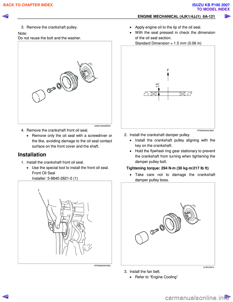
3. Remove the crankshaft pulley.
Note:
Do not reuse the bolt and the washer.
LNW 61ASH005301
4. Remove the crankshaft front oil seal.
• Remove only the oil seal with a screwdriver o
r
the like, avoiding damage to the oil seal contact
surface on the front cover and the shaft.
Installation
1. Install the crankshaft front oil seal. • Use the special tool to install the front oil seal.
Front Oil Seal
Installer: 5-8840-2821-0 (1)
RTW 56ASH016501
• Apply engine oil to the lip of the oil seal.
• W ith the seal pressed in check the dimension
of the oil seal section.
Standard Dimension = 1.5 mm (0.06 in)
RTW 56ASH016601
2. Install the crankshaft damper pulley.
• Install the crankshaft pulley aligning with the
key on the crankshaft.
• Hold the flywheel ring gear stationary to prevent
the crankshaft from turning when tightening the
damper pulley bolt.
Tightening torque: 294 N ⋅
⋅⋅
⋅
m (30 kg ⋅
⋅⋅
⋅
m/217 lb ft)
• Take care not to damage the crankshaft
damper pulley boss.
014R100014
3. Install the fan belt.
• Refer to “Engine Cooling”
BACK TO CHAPTER INDEX
TO MODEL INDEX
ISUZU KB P190 2007
Page 1516 of 6020
6A-156 ENGINE MECHANICAL (4JK1/4JJ1)
Oil Pump
Components
RTW 66AMF000701
Legend 1. Bolt 2. Oil Pump Assembly
Removal
1. Drain the engine coolant.
2. Remove the radiator upper hose.
3. Remove the upper fan shroud.
4. Remove the fan and fan clutch. • Loosen the fan clutch nuts.
• Remove the fan together with the fan clutch.
Take care not to damage the radiator core.
5. Remove the fan drive belt and pulley. • Loosen the tension adjust bolt on the generato
r
and A/C.
• Remove the fan drive belt with the fan pulley.
6. Remove the lower fan shroud.
7. Disconnect the power steering pump. • Disconnect the bracket of the power steering oil
hose clip (1).
LTW 56ASH000101
BACK TO CHAPTER INDEX
TO MODEL INDEX
ISUZU KB P190 2007
Page 1520 of 6020
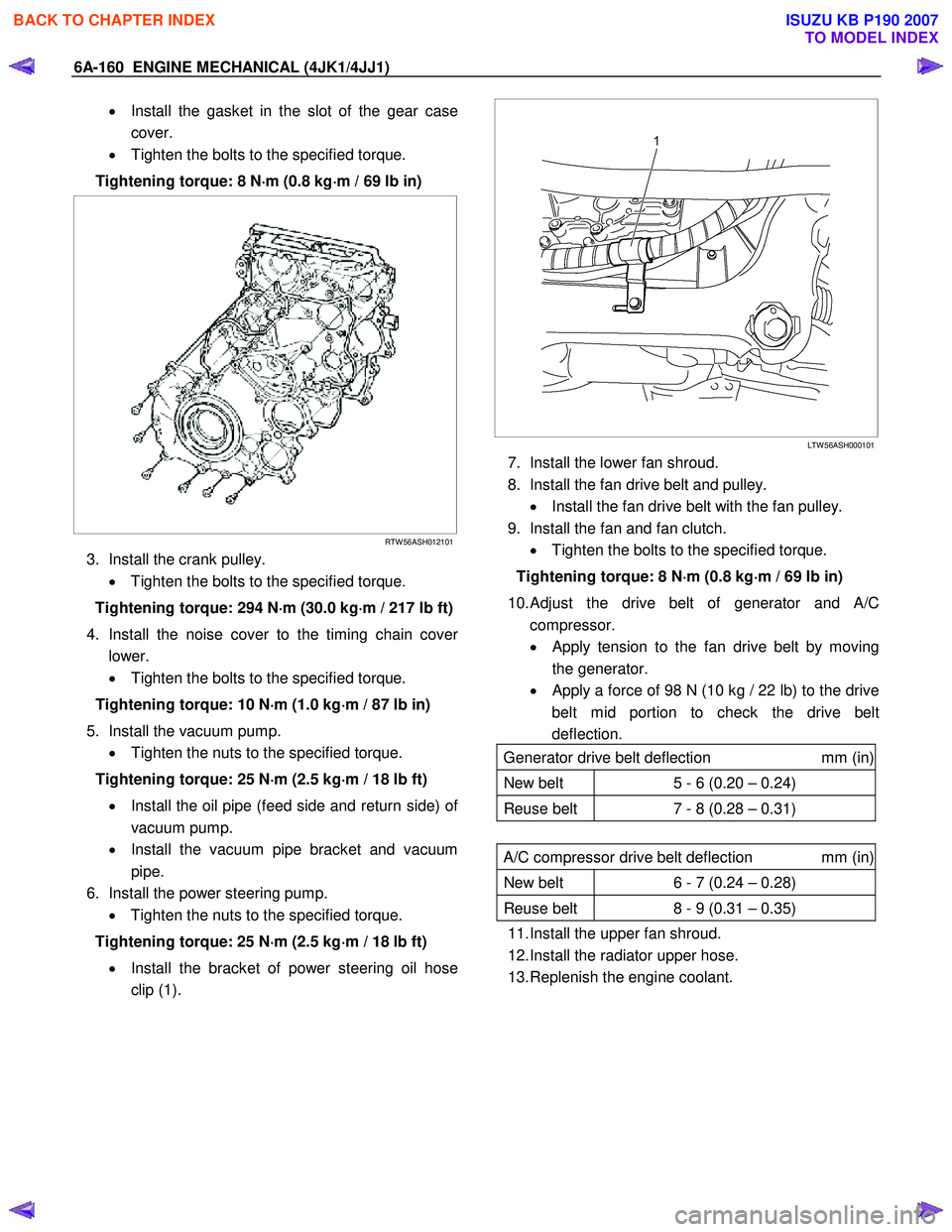
6A-160 ENGINE MECHANICAL (4JK1/4JJ1)
• Install the gasket in the slot of the gear case
cover.
• Tighten the bolts to the specified torque.
Tightening torque: 8 N ⋅
⋅⋅
⋅
m (0.8 kg ⋅
⋅⋅
⋅
m / 69 lb in)
RTW 56ASH012101
3. Install the crank pulley.
• Tighten the bolts to the specified torque.
Tightening torque: 294 N ⋅
⋅⋅
⋅
m (30.0 kg ⋅
⋅⋅
⋅
m / 217 lb ft)
4. Install the noise cover to the timing chain cove
r
lower.
• Tighten the bolts to the specified torque.
Tightening torque: 10 N ⋅
⋅⋅
⋅
m (1.0 kg ⋅
⋅⋅
⋅
m / 87 lb in)
5. Install the vacuum pump. • Tighten the nuts to the specified torque.
Tightening torque: 25 N ⋅
⋅⋅
⋅
m (2.5 kg ⋅
⋅⋅
⋅
m / 18 lb ft)
• Install the oil pipe (feed side and return side) o
f
vacuum pump.
• Install the vacuum pipe bracket and vacuum
pipe.
6. Install the power steering pump. • Tighten the nuts to the specified torque.
Tightening torque: 25 N ⋅
⋅⋅
⋅
m (2.5 kg ⋅
⋅⋅
⋅
m / 18 lb ft)
• Install the bracket of power steering oil hose
clip (1).
LTW 56ASH000101
7. Install the lower fan shroud.
8. Install the fan drive belt and pulley. • Install the fan drive belt with the fan pulley.
9. Install the fan and fan clutch. • Tighten the bolts to the specified torque.
Tightening torque: 8 N ⋅
⋅⋅
⋅
m (0.8 kg ⋅
⋅⋅
⋅
m / 69 lb in)
10.
Adjust the drive belt of generator and A/C
compressor.
• Apply tension to the fan drive belt by moving
the generator.
•
Apply a force of 98 N (10 kg / 22 lb) to the drive
belt mid portion to check the drive belt
deflection.
Generator drive belt deflection mm (in)
New belt 5 - 6 (0.20 – 0.24)
Reuse belt 7 - 8 (0.28 – 0.31)
A/C compressor drive belt deflection mm (in)
New belt 6 - 7 (0.24 – 0.28)
Reuse belt 8 - 9 (0.31 – 0.35)
11. Install the upper fan shroud.
12. Install the radiator upper hose.
13. Replenish the engine coolant.
BACK TO CHAPTER INDEX
TO MODEL INDEX
ISUZU KB P190 2007
Page 1531 of 6020
6B-8 ENGINE COOLING (4JK1/4JJ1)
Water Pump
Read this Section carefully before performing any
removal and installation procedure. This Section gives
you important points as well as the order of operation.
Be sure that you understand everything in this Section
before you begin.
Removal
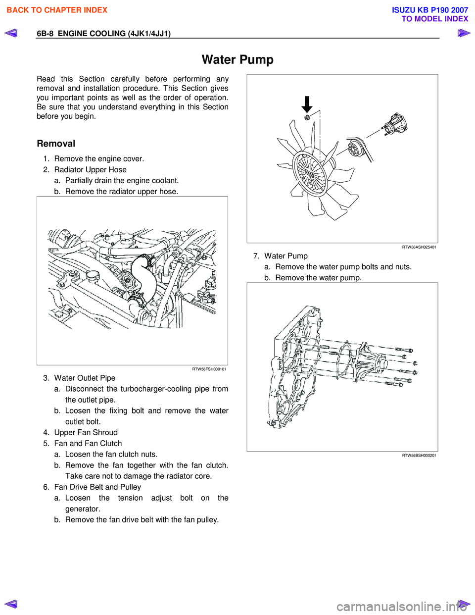
1. Remove the engine cover.
2. Radiator Upper Hose a. Partially drain the engine coolant.
b. Remove the radiator upper hose.
RTW 56FSH000101
3. W ater Outlet Pipe
a. Disconnect the turbocharger-cooling pipe from the outlet pipe.
b. Loosen the fixing bolt and remove the wate
r
outlet bolt.
4. Upper Fan Shroud
5. Fan and Fan Clutch a. Loosen the fan clutch nuts.
b. Remove the fan together with the fan clutch. Take care not to damage the radiator core.
6. Fan Drive Belt and Pulley a. Loosen the tension adjust bolt on the generator.
b. Remove the fan drive belt with the fan pulley.
RTW 56ASH025401
7. W ater Pump
a. Remove the water pump bolts and nuts.
b. Remove the water pump.
RTW 56BSH000201
BACK TO CHAPTER INDEX
TO MODEL INDEX
ISUZU KB P190 2007
Page 1532 of 6020
ENGINE COOLING (4JK1/4JJ1) 6B-9
Inspection and Repair
The water pump is not disassembled type.
Make necessary parts replacement if extreme wear o
r
damage is found during inspection. Should any of the
following problems occur, the entire water pump
assembly must be replaced.
• Cracks in the water pump body.
• Coolant leakage from the sealed unit.
• Excessive radial play or abnormal noise in the fan
center when rotated by hand.
• Excessive thrust play in the fan center (Standard
play: less than 0.2 mm (0.0078 in)).
• Cracks or corrosion in the impeller.
Installation
1. W ater Pump
RTW 56BSH000201
a. Install the water pump with a new gasket.
b. Tighten bolts and nuts to specified torque.
Water Pump Nut/Bolt Torque: 25 N·m (2.5 kg·m /18 lb ft)
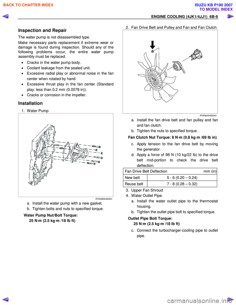
2. Fan Drive Belt and Pulley and Fan and Fan Clutch.
RTW 56ASH025401
a. Install the fan drive belt and fan pulley and fan
and fan clutch.
b. Tighten the nuts to specified torque.
Fan Clutch Nut Torque: 8 N·m (0.8 kg·m /69 lb in) c. Apply tension to the fan drive belt by moving the generator.
d. Apply a force of 98 N (10 kg/22 lb) to the drive belt mid-portion to check the drive belt
deflection.
Fan Drive Belt Deflection mm (in)
New belt 5 - 6 (0.20 – 0.24)
Reuse belt 7 - 8 (0.28 – 0.32)
3. Upper Fan Shroud
4. W ater Outlet Pipe.
a. Install the water outlet pipe to the thermostat housing.
b. Tighten the outlet pipe bolt to specified torque.
Outlet Pipe Bolt Torque: 25 N·m (2.5 kg·m /18 lb ft)
c. Connect the turbocharger-cooling pipe to outlet pipe.
BACK TO CHAPTER INDEX
TO MODEL INDEX
ISUZU KB P190 2007
Page 1569 of 6020
6C-28 FUEL SYSTEM (4JK1/4JJ1)
Removal
1. Partially drain the engine coolant.
Refer to drain procedure for engine cooling in this manual.
2. Remove the radiator upper hose.
RTW 56FSH000101
3. Remove the fan guide.
RTW 46BSH000101
Legend
1. Fan Guide
2. Clips
3. Lower Fan Guide
4. Fan Shroud
4. Remove the cooling Fan.
RTW 56ASH025401
5. Remove the A/C compressor drive belt.
6. Remove the A/C compressor adjust pulley.
RTW 56ASH010601
Legend
1. Bolt
2. Nut
7. Remove the battery.
BACK TO CHAPTER INDEX
TO MODEL INDEX
ISUZU KB P190 2007