2007 ISUZU KB P190 ECO mode
[x] Cancel search: ECO modePage 2012 of 6020
6-12 ENGINE DIAGNOSIS (C24SE)
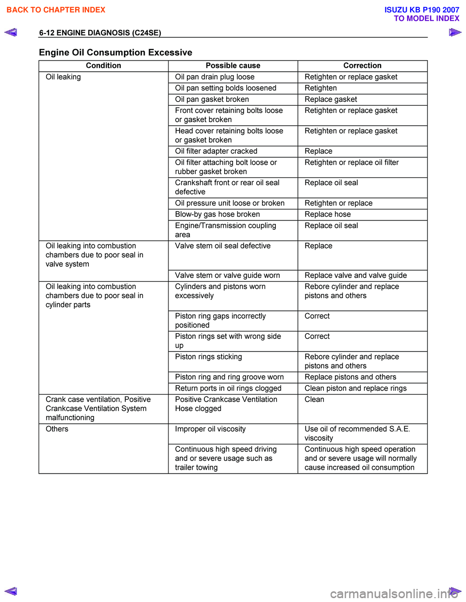
Engine Oil Consumption Excessive
Condition Possible cause Correction
Oil leaking Oil pan drain plug loose Retighten or replace gasket
Oil pan setting bolds loosened Retighten
Oil pan gasket broken Replace gasket
Front cover retaining bolts loose
or gasket broken Retighten or replace gasket
Head cover retaining bolts loose
or gasket broken Retighten or replace gasket
Oil filter adapter cracked Replace
Oil filter attaching bolt loose or
rubber gasket broken Retighten or replace oil filter
Crankshaft front or rear oil seal
defective Replace oil seal
Oil pressure unit loose or broken Retighten or replace
Blow-by gas hose broken Replace hose
Engine/Transmission coupling
area Replace oil seal
Oil leaking into combustion
chambers due to poor seal in
valve system Valve stem oil seal defective Replace
Valve stem or valve guide worn Replace valve and valve guide
Oil leaking into combustion
chambers due to poor seal in
cylinder parts Cylinders and pistons worn
excessively Rebore cylinder and replace
pistons and others
Piston ring gaps incorrectly
positioned Correct
Piston rings set with wrong side
up Correct
Piston rings sticking Rebore cylinder and replace
pistons and others
Piston ring and ring groove worn Replace pistons and others
Return ports in oil rings clogged Clean piston and replace rings
Crank case ventilation, Positive
Crankcase Ventilation System
malfunctioning Positive Crankcase Ventilation
Hose clogged Clean
Others
Improper oil viscosity Use oil of recommended S.A.E.
viscosity
Continuous high speed driving
and or severe usage such as
trailer towing Continuous high speed operation
and or severe usage will normally
cause increased oil consumption
BACK TO CHAPTER INDEX
TO MODEL INDEX
ISUZU KB P190 2007
Page 2014 of 6020
6-14 ENGINE DIAGNOSIS (C24SE)
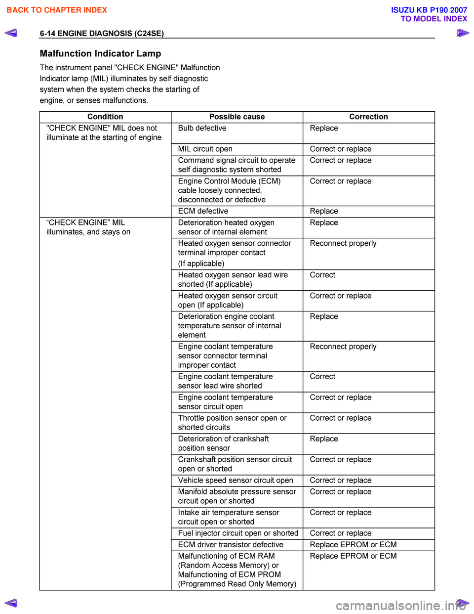
Malfunction Indicator Lamp
The instrument panel "CHECK ENGINE" Malfunction
Indicator lamp (MIL) illuminates by self diagnostic
system when the system checks the starting of
engine, or senses malfunctions.
Condition Possible cause Correction
"CHECK ENGINE" MIL does not
illuminate at the starting of engine Bulb defective Replace
MIL circuit open Correct or replace
Command signal circuit to operate
self diagnostic system shorted Correct or replace
Engine Control Module (ECM)
cable loosely connected,
disconnected or defective Correct or replace
ECM
defective Replace
“CHECK ENGINE” MIL
illuminates, and stays on Deterioration heated oxygen
sensor of internal element Replace
Heated oxygen sensor connector
terminal improper contact
(If applicable) Reconnect properly
Heated oxygen sensor lead wire
shorted (If applicable) Correct
Heated oxygen sensor circuit
open (If applicable) Correct or replace
Deterioration engine coolant
temperature sensor of internal
element Replace
Engine coolant temperature
sensor connector terminal
improper contact Reconnect properly
Engine coolant temperature
sensor lead wire shorted Correct
Engine coolant temperature
sensor circuit open Correct or replace
Throttle position sensor open or
shorted circuits Correct or replace
Deterioration of crankshaft
position sensor Replace
Crankshaft position sensor circuit
open or shorted Correct or replace
Vehicle speed sensor circuit open Correct or replace
Manifold absolute pressure sensor
circuit open or shorted Correct or replace
Intake air temperature sensor
circuit open or shorted Correct or replace
Fuel injector circuit open or shorted Correct or replace
ECM driver transistor defective Replace EPROM or ECM
Malfunctioning of ECM RAM
(Random Access Memory) or
Malfunctioning of ECM PROM
(Programmed Read Only Memory) Replace EPROM or ECM
BACK TO CHAPTER INDEX
TO MODEL INDEX
ISUZU KB P190 2007
Page 2017 of 6020
ENGINE MECHANICAL (C24SE) 6A-3
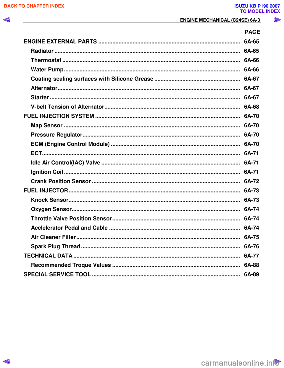
PAGE
ENGINE EXTERNAL PARTS ........................................................................................... 6A-65 Radiator ....................................................................................................................... 6A-65
Thermostat .................................................................................................................. 6A -66
Water Pump ................................................................................................................. 6A- 66
Coating sealing surfaces with Silicone Grease ....................................................... 6A-67
Alternator ..................................................................................................................... 6A-67
Starter ........................................................................................................................ .. 6A-67
V-belt Tension of Alternator ....................................................................................... 6A-68
FUEL INJECTION SYSTEM ............................................................................................. 6A-70 Map Sensor ................................................................................................................. 6A- 70
Pressure Regulator..................................................................................................... 6A-70
ECM (Engine Control Module) ................................................................................... 6A-70
ECT............................................................................................................................ ... 6A-71
Idle Air Control(IAC) Valve ......................................................................................... 6A-71
Ignition Coil ................................................................................................................. 6A-71
Crank Position Sensor ............................................................................................... 6A-72
FUEL INJECTOR .............................................................................................................. 6A- 73
Knock Sensor.............................................................................................................. 6A-7 3
Oxygen Sensor............................................................................................................ 6A-74
Throttle Valve Position Sensor .................................................................................. 6A-74
Acclelerator Pedal and Cable .................................................................................... 6A-74
Air Cleaner Filter ......................................................................................................... 6A- 75
Spark Plug Thread ...................................................................................................... 6A-76
TECHNICAL DATA ........................................................................................................... 6A-77
Recommended Troque Values .................................................................................. 6A-88
SPECIAL SERVICE TOOL ............................................................................................... 6A-89
BACK TO CHAPTER INDEX
TO MODEL INDEX
ISUZU KB P190 2007
Page 2027 of 6020

ENGINE MECHANICAL (C24SE) 6A-13
Valve System C24SE
Actuation Type Direct-acting Inverted Bucked Tappet
Valve Clearance Adjustment Hydraulic
Valve Rotor Type None
Inlet-Valve Material Chromium Alloyed Steel
-Seat Insert MaterialSintered Iron
Exhaust-Valve Material Head: Cr-Mn-Ni Alloyed Shaft: Cr-Si Alloyed &Cr plated
-Seat Insert MaterialSintered Iron
Valve Spring Material GME 06 100-C1
Valve Guide Material QS 13 MR 00
Valve Seal Type Lip
Water Pump C24SE
Type Centrifugal
Drive-Material &Type HNBR Toothed-belt
Bearing Type Double Row Ball
Shaft Seal Type Mechanical Ceramic
Thermostat-Coolant C24SE
Type Bypass
Oil Pump & Filter C24SE
Type Gear Pump
Location Front of Engine
Drive Direct Crankshaft Driven
Filter Type Full Flow with Bypass for blocked filter
Oil & Oil Reservoir C24SE
Reservoir-Description & Location 1-piece below Engine
Reservoir Material Aluminum Alloy (pressure cast)
Replacement Oil Fill Volume
-W ith Filter change4.25liters
-W ithout Filter change 4.00liters
Recommended Oil-Run-in 10W /30SG
-Service (above-18°C) 10W /40SG
-Service (below-18°C) 5W /30SG
Oil Classification API&CCMC
Ignition Components C24SE
Spark Plugs Conventional
Type Electronic Spark Control
No. of Coils &Type 2 Solid State
Coil Location Engine-mounted
Ignition Lead Type Inductive (hi-resistance)
BACK TO CHAPTER INDEX
TO MODEL INDEX
ISUZU KB P190 2007
Page 2030 of 6020
6A-16 ENGINE MECHANICAL (C24SE)
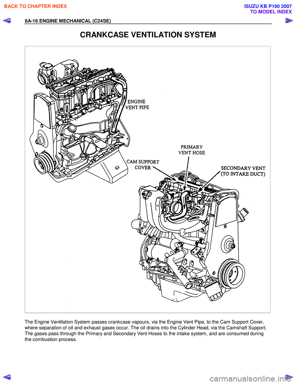
CRANKCASE VENTILATION SYSTEM
The Engine Ventilation System passes crankcase vapours, via the Engine Vent Pipe, to the Cam Support Cover,
where separation of oil and exhaust gases occur. The oil drains into the Cylinder Head, via the Camshaft Support.
The gases pass through the Primary and Secondary Vent Hoses to the intake system, and are consumed during
the combustion process.
BACK TO CHAPTER INDEX
TO MODEL INDEX
ISUZU KB P190 2007
Page 2058 of 6020
6A-44 ENGINE MECHANICAL (C24SE)
Valve, Grind
Valves can be reused once or twice after regrinding-only if
there are no crater-like burns on the valve cone.
Excessive grinding can cause the upper valve head edge to
become too thin.
Important!
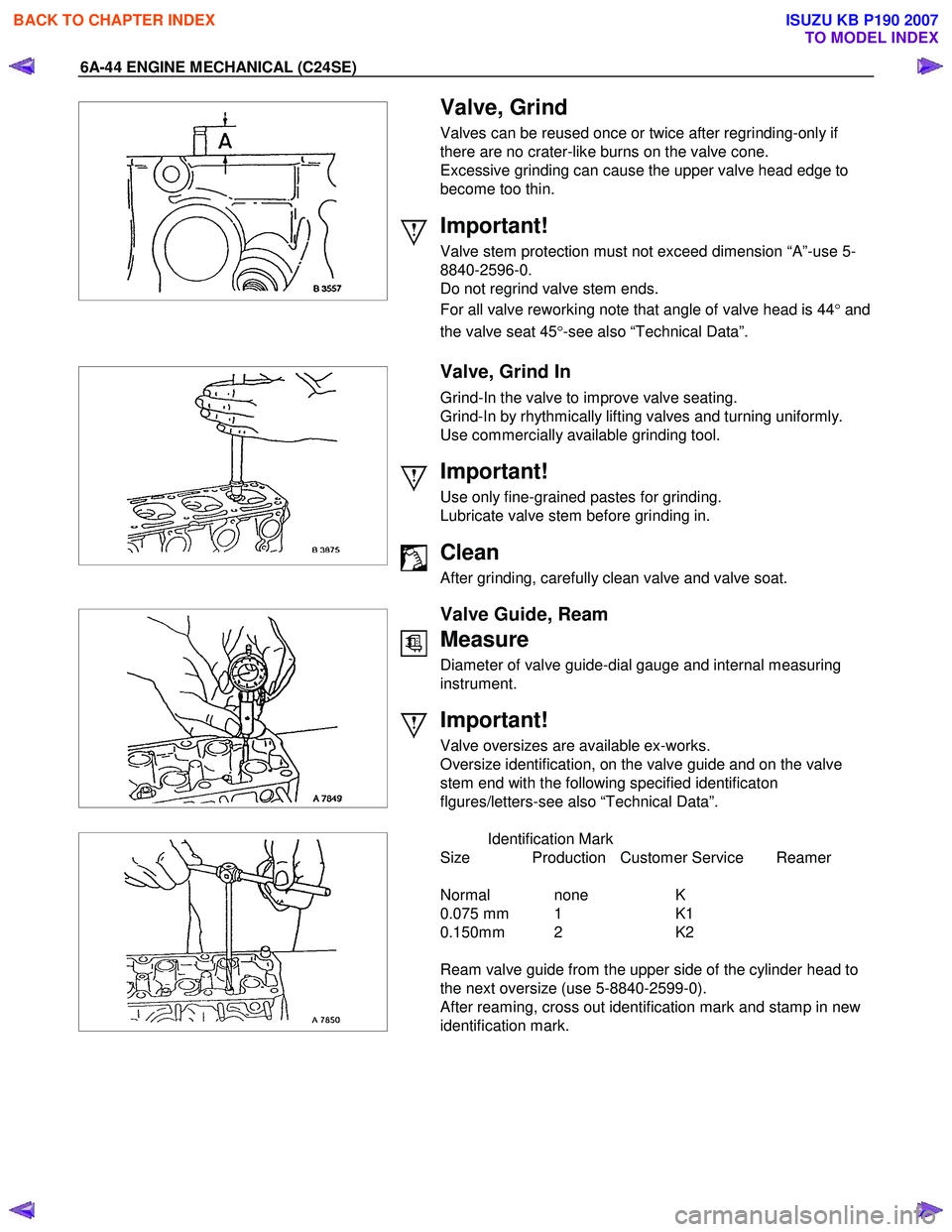
Valve stem protection must not exceed dimension “A”-use 5-
8840-2596-0.
Do not regrind valve stem ends.
For all valve reworking note that angle of valve head is 44 °and
the valve seat 45 °-see also “Technical Data”.
Valve, Grind In
Grind-In the valve to improve valve seating.
Grind-In by rhythmically lifting valves and turning uniformly.
Use commercially available grinding tool.
Important!
Use only fine-grained pastes for grinding.
Lubricate valve stem before grinding in.
Clean
After grinding, carefully clean valve and valve soat.
Valve Guide, Ream
Measure
Diameter of valve guide-dial gauge and internal measuring
instrument.
Important!
Valve oversizes are available ex-works.
Oversize identification, on the valve guide and on the valve
stem end with the following specified identificaton
flgures/letters-see also “Technical Data”.
Identification Mark
Size Production Customer Service Reamer
Normal none K
0.075 mm 1 K1
0.150mm 2 K2
Ream valve guide from the upper side of the cylinder head to
the next oversize (use 5-8840-2599-0).
After reaming, cross out identification mark and stamp in new
identification mark.
BACK TO CHAPTER INDEX
TO MODEL INDEX
ISUZU KB P190 2007
Page 2064 of 6020
6A-50 ENGINE MECHANICAL (C24SE)
Clean
Sealing surfaces.
013RW 004
Installation
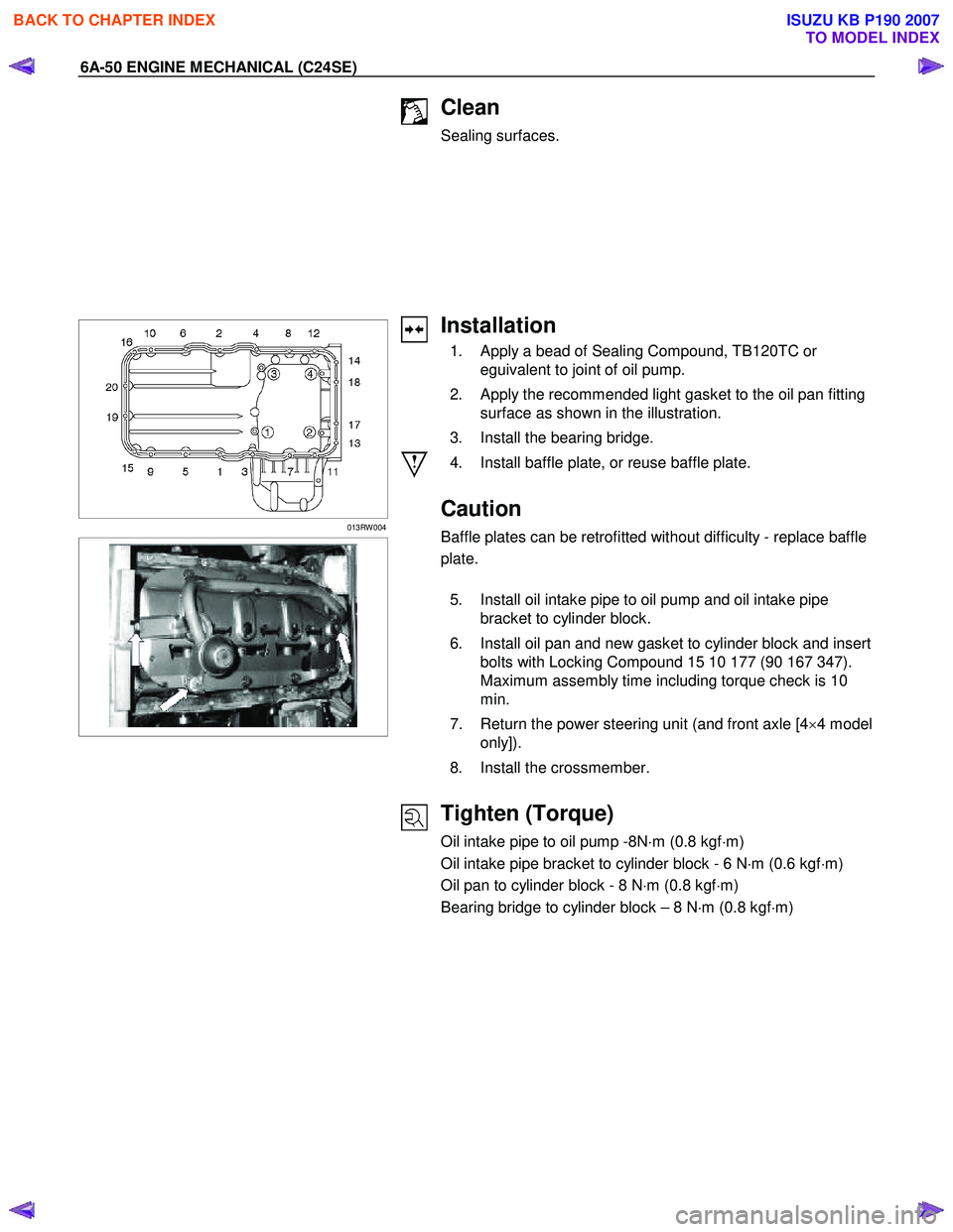
1. Apply a bead of Sealing Compound, TB120TC or eguivalent to joint of oil pump.
2. Apply the recommended light gasket to the oil pan fitting surface as shown in the illustration.
3. Install the bearing bridge.
4. Install baffle plate, or reuse baffle plate.
Caution
Baffle plates can be retrofitted without difficulty - replace baffle
plate.
5. Install oil intake pipe to oil pump and oil intake pipe bracket to cylinder block.
6. Install oil pan and new gasket to cylinder block and insert bolts with Locking Compound 15 10 177 (90 167 347).
Maximum assembly time including torque check is 10
min.
7. Return the power steering unit (and front axle [4 ×4 model
only]).
8. Install the crossmember.
Tighten (Torque)
Oil intake pipe to oil pump -8N ⋅m (0.8 kgf ⋅m)
Oil intake pipe bracket to cylinder block - 6 N ⋅m (0.6 kgf ⋅m)
Oil pan to cylinder block - 8 N ⋅m (0.8 kgf ⋅m)
Bearing bridge to cylinder block – 8 N ⋅m (0.8 kgf ⋅m)
BACK TO CHAPTER INDEX
TO MODEL INDEX
ISUZU KB P190 2007
Page 2068 of 6020
6A-54 ENGINE MECHANICAL (C24SE)
RTW 46ASH002401
Installation
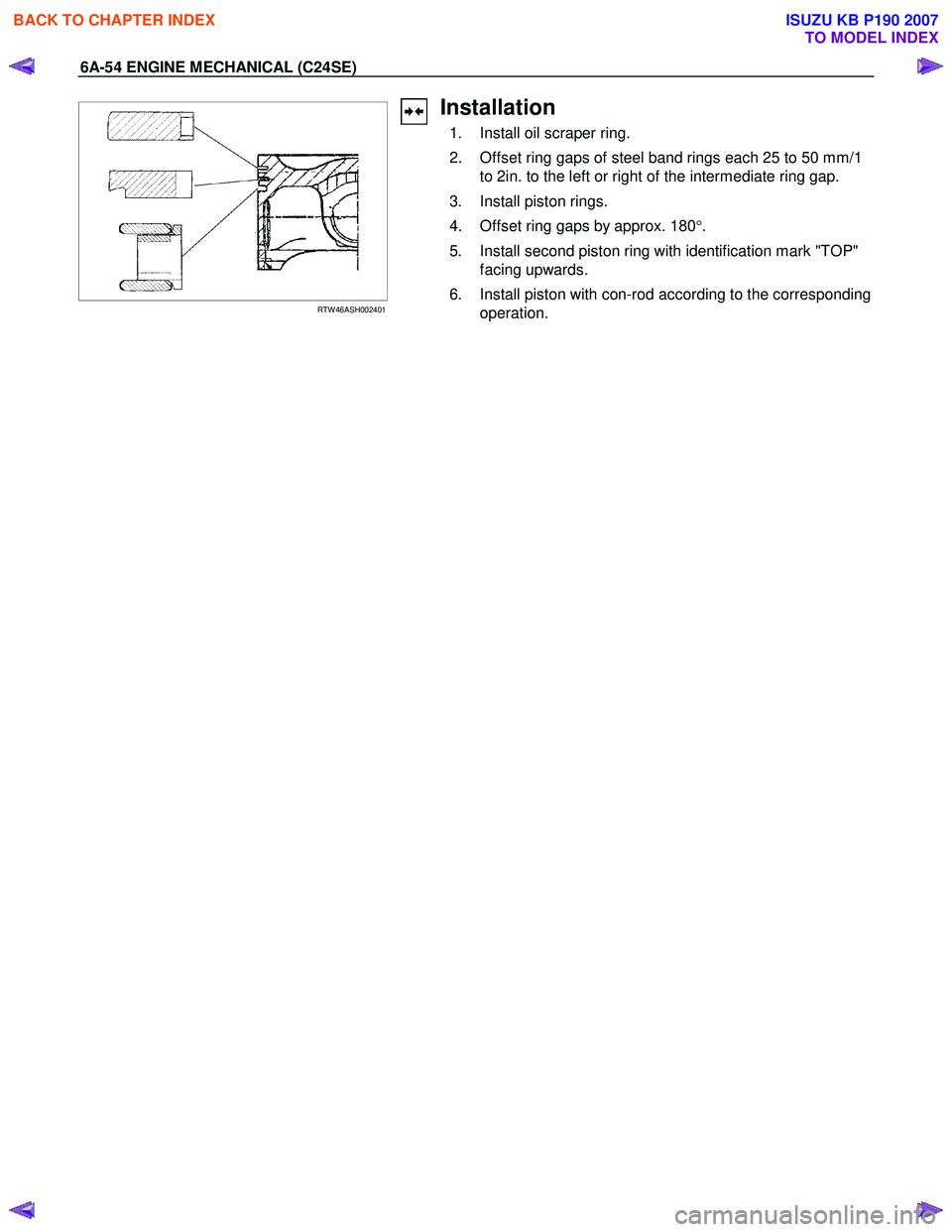
1. Install oil scraper ring.
2. Offset ring gaps of steel band rings each 25 to 50 mm/1 to 2in. to the left or right of the intermediate ring gap.
3. Install piston rings.
4. Offset ring gaps by approx. 180 °.
5. Install second piston ring with identification mark "TOP" facing upwards.
6. Install piston with con-rod according to the corresponding operation.
BACK TO CHAPTER INDEX
TO MODEL INDEX
ISUZU KB P190 2007