2007 ISUZU KB P190 ECO mode
[x] Cancel search: ECO modePage 2072 of 6020
6A-58 ENGINE MECHANICAL (C24SE)
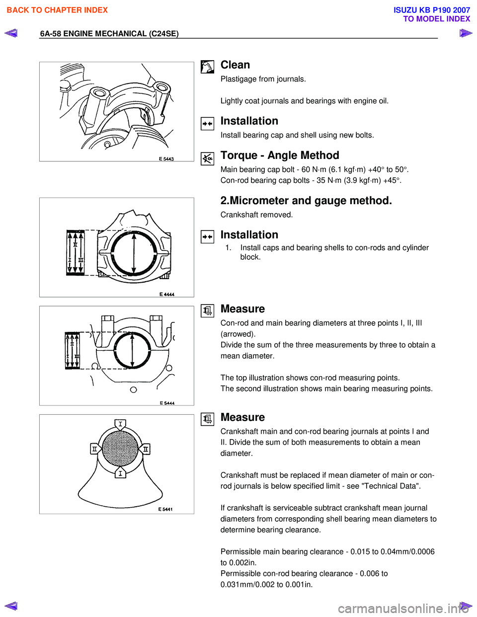
Clean
Plastigage from journals.
Lightly coat journals and bearings with engine oil.
Installation
Install bearing cap and shell using new bolts.
Torque - Angle Method
Main bearing cap bolt - 60 N ⋅m (6.1 kgf ⋅m) +40 ° to 50 °.
Con-rod bearing cap bolts - 35 N ⋅m (3.9 kgf ⋅m) +45 °.
2.Micrometer and gauge method.
Crankshaft removed.
Installation
1. Install caps and bearing shells to con-rods and cylinder block.
Measure
Con-rod and main bearing diameters at three points I, II, III
(arrowed).
Divide the sum of the three measurements by three to obtain a
mean diameter.
The top illustration shows con-rod measuring points.
The second illustration shows main bearing measuring points.
Measure
Crankshaft main and con-rod bearing journals at points I and
II. Divide the sum of both measurements to obtain a mean
diameter.
Crankshaft must be replaced if mean diameter of main or con-
rod journals is below specified limit - see "Technical Data".
If crankshaft is serviceable subtract crankshaft mean journal
diameters from corresponding shell bearing mean diameters to
determine bearing clearance.
Permissible main bearing clearance - 0.015 to 0.04mm/0.0006
to 0.002in.
Permissible con-rod bearing clearance - 0.006 to
0.031mm/0.002 to 0.001in.
BACK TO CHAPTER INDEX
TO MODEL INDEX
ISUZU KB P190 2007
Page 2073 of 6020
ENGINE MECHANICAL (C24SE) 6A-59
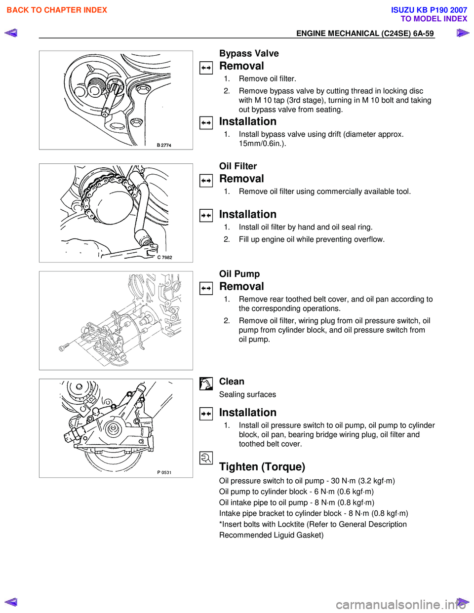
Bypass Valve
Removal
1. Remove oil filter.
2. Remove bypass valve by cutting thread in locking disc with M 10 tap (3rd stage), turning in M 10 bolt and taking
out bypass valve from seating.
Installation
1. Install bypass valve using drift (diameter approx. 15mm/0.6in.).
Oil Filter
Removal
1. Remove oil filter using commercially available tool.
Installation
1. Install oil filter by hand and oil seal ring.
2. Fill up engine oil while preventing overflow.
Oil Pump
Removal
1. Remove rear toothed belt cover, and oil pan according to the corresponding operations.
2. Remove oil filter, wiring plug from oil pressure switch, oil pump from cylinder block, and oil pressure switch from
oil pump.
Clean
Sealing surfaces
Installation
1. Install oil pressure switch to oil pump, oil pump to cylinder
block, oil pan, bearing bridge wiring plug, oil filter and
toothed belt cover.
Tighten (Torque)
Oil pressure switch to oil pump - 30 N ⋅m (3.2 kgf ⋅m)
Oil pump to cylinder block - 6 N ⋅m (0.6 kgf ⋅m)
Oil intake pipe to oil pump - 8 N ⋅m (0.8 kgf ⋅m)
Intake pipe bracket to cylinder block - 8 N ⋅m (0.8 kgf ⋅m)
*Insert bolts with Locktite (Refer to General Description
Recommended Liguid Gasket)
BACK TO CHAPTER INDEX
TO MODEL INDEX
ISUZU KB P190 2007
Page 2090 of 6020
6A-76 ENGINE MECHANICAL (C24SE)
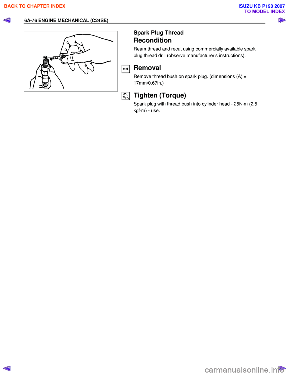
Spark Plug Thread
Recondition
Ream thread and recut using commercially available spark
plug thread drill (observe manufacturer's instructions).
Removal
Remove thread bush on spark plug. (dimensions (A) =
17mm/0.67in.)
Tighten (Torque)
Spark plug with thread bush into cylinder head - 25N ⋅m (2.5
kgf ⋅m) - use.
BACK TO CHAPTER INDEX
TO MODEL INDEX
ISUZU KB P190 2007
Page 2102 of 6020
6A-88 ENGINE MECHANICAL (C24SE)
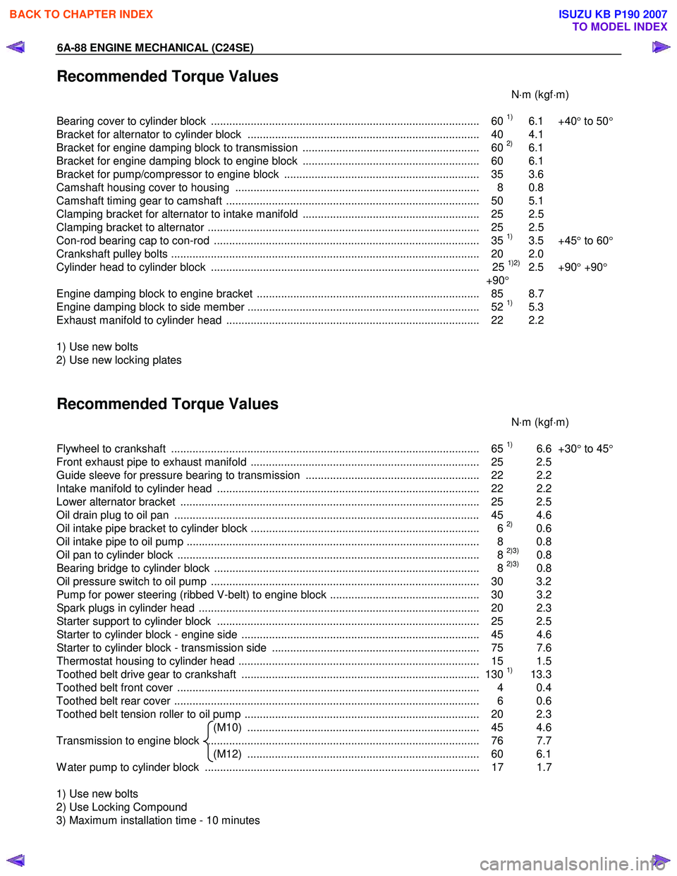
Recommended Torque Values
N⋅m (kgf ⋅m)
Bearing cover to cylinder block ........................................................................................ 60
1) 6.1 +40 ° to 50 °
Bracket for alternator to cylinder block ............................................................................ 40 4.1
Bracket for engine damping block to transmission .......................................................... 60
2) 6.1
Bracket for engine damping block to engine block .......................................................... 60 6.1
Bracket for pump/compressor to engine block ................................................................ 35 3.6
Camshaft housing cover to housing ................................................................................ 8 0.8
Camshaft timing gear to camshaft ................................................................................... 50 5.1
Clamping bracket for alternator to intake manifold .......................................................... 25 2.5
Clamping bracket to alternator ......................................................................................... 25 2.5
Con-rod bearing cap to con-rod ....................................................................................... 35
1) 3.5 +45 ° to 60 °
Crankshaft pulley bolts ..................................................................................................... 2 0 2.0
Cylinder head to cylinder block ........................................................................................ 25
1)2) 2.5 +90 ° +90 °
+90 °
Engine damping block to engine bracket ......................................................................... 85 8.7
Engine damping block to side member ............................................................................ 52
1) 5.3
Exhaust manifold to cylinder head ................................................................................... 22 2.2
1) Use new bolts
2) Use new locking plates
Recommended Torque Values
N⋅m (kgf ⋅m)
Flywheel to crankshaft ..................................................................................................... 65
1) 6.6 +30° to 45 °
Front exhaust pipe to exhaust manifold ........................................................................... 25 2.5
Guide sleeve for pressure bearing to transmission ......................................................... 22 2.2
Intake manifold to cylinder head ...................................................................................... 22 2.2
Lower alternator bracket .................................................................................................. 25 2.5
Oil drain plug to oil pan .................................................................................................... 45 4.6
Oil intake pipe bracket to cylinder block ........................................................................... 6
2) 0.6
Oil intake pipe to oil pump ................................................................................................ 8 0.8
Oil pan to cylinder block ................................................................................................... 8
2)3) 0.8
Bearing bridge to cylinder block ....................................................................................... 8 2)3) 0.8
Oil pressure switch to oil pump ........................................................................................ 30 3.2
Pump for power steering (ribbed V-belt) to engine block ................................................. 30 3.2
Spark plugs in cylinder head ............................................................................................ 20 2. 3
Starter support to cylinder block ...................................................................................... 25 2.5
Starter to cylinder block - engine side .............................................................................. 45 4.6
Starter to cylinder block - transmission side .................................................................... 75 7.6
Thermostat housing to cylinder head ............................................................................... 15 1.5
Toothed belt drive gear to crankshaft .............................................................................. 130
1) 13.3
Toothed belt front cover ................................................................................................... 4 0.4
Toothed belt rear cover .................................................................................................... 6 0.6
Toothed belt tension roller to oil pump ............................................................................. 20 2.3 (M10) ............................................................................ 45 4.6
Transmission to engine block ......................................................................................... 76 7.7 (M12) ............................................................................ 60 6.1
W ater pump to cylinder block .......................................................................................... 17 1.7
1) Use new bolts
2) Use Locking Compound
3) Maximum installation time - 10 minutes
BACK TO CHAPTER INDEX
TO MODEL INDEX
ISUZU KB P190 2007
Page 2125 of 6020

ENGINE FUEL (C24SE) 6C-7
Fuel Pump Flow Test
If reduction of fuel supply is suspected, perform the
following checks.
1. Make sure that there is fuel in the tank.
2. W ith the engine running, check the fuel feed pipe and hose from fuel tank to injector for evidence o
f
leakage. Retighten, if pipe or hose connection is
loose. Also, check pipes and hoses for squashing
or clogging.
3. Insert the hose from fuel feed pipe into a clean container, and check for fuel pump flow rate.
4. Connect the pump relay terminals (2) with a jumper wire (1) as shown and start the fuel pump
to measure delivery.
RTW 36CSH000201
CAUTION: Never generate sparks when connecting
a jumper wire.
Delivery Delivery
15 seconds 0.38 liters minimum
If the measure value is out of standard, conduct the
pressure test.
Pressure test
For the pressure test to the fuel system, see Section 6E
“Fuel Control System".
BACK TO CHAPTER INDEX
TO MODEL INDEX
ISUZU KB P190 2007
Page 2127 of 6020
ENGINE FUEL (C24SE) 6C-9
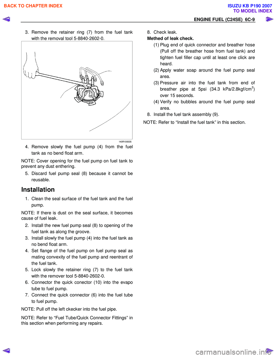
3. Remove the retainer ring (7) from the fuel tank
with the removal tool 5-8840-2602-0.
140R100035
4. Remove slowly the fuel pump (4) from the fuel
tank as no bend float arm.
NOTE: Cover opening for the fuel pump on fuel tank to
prevent any dust enthering.
5. Discard fuel pump seal (8) because it cannot be
reusable.
Installation
1. Clean the seal surface of the fuel tank and the fuel pump.
NOTE: If there is dust on the seal surface, it becomes
cause of fuel leak.
2. Install the new fuel pump seal (8) to opening of the fuel tank as along the groove.
3. Install slowly the fuel pump (4) into the fuel tank as no bend float arm.
4. Set flange of the fuel pump on fuel pump seal as
mating convexity of the fuel pump and reentrant o
f
the fuel tank.
5. Lock slowly the retainer ring (7) to the fuel tank
with the remover tool 5-8840-2602-0.
6. Connector the quick conector (10) into the evapo tube to fuel pump.
7. Connect the quick connector (6) into the fuel tube
to fuel pump.
NOTE: Pull off the left ckecker into the fuel pipe.
NOTE: Refer to “Fuel Tube/Quick Connector Fittings” in
this section when performing any repairs.
8. Check leak.
Methed of leak check.
(1) Plug end of quick connector and breather hose
(Pull off the breather hose from fuel tank) and
tighten fuel filler cap until at least one click are
heard.
(2)
Apply water soap around the fuel pump seal
area.
(3) Pressure air into the fuel tank from end o
f
breather pipe at 5psi (34.3 kPa/2.8kgf/cm2)
over 15 seconds.
(4) Verify no bubbles around the fuel pump seal
area.
8. Install the fuel tank assembly (9).
NOTE: Refer to “Install the fuel tank” in this section.
BACK TO CHAPTER INDEX
TO MODEL INDEX
ISUZU KB P190 2007
Page 2129 of 6020
ENGINE FUEL (C24SE) 6C-11
140R100028
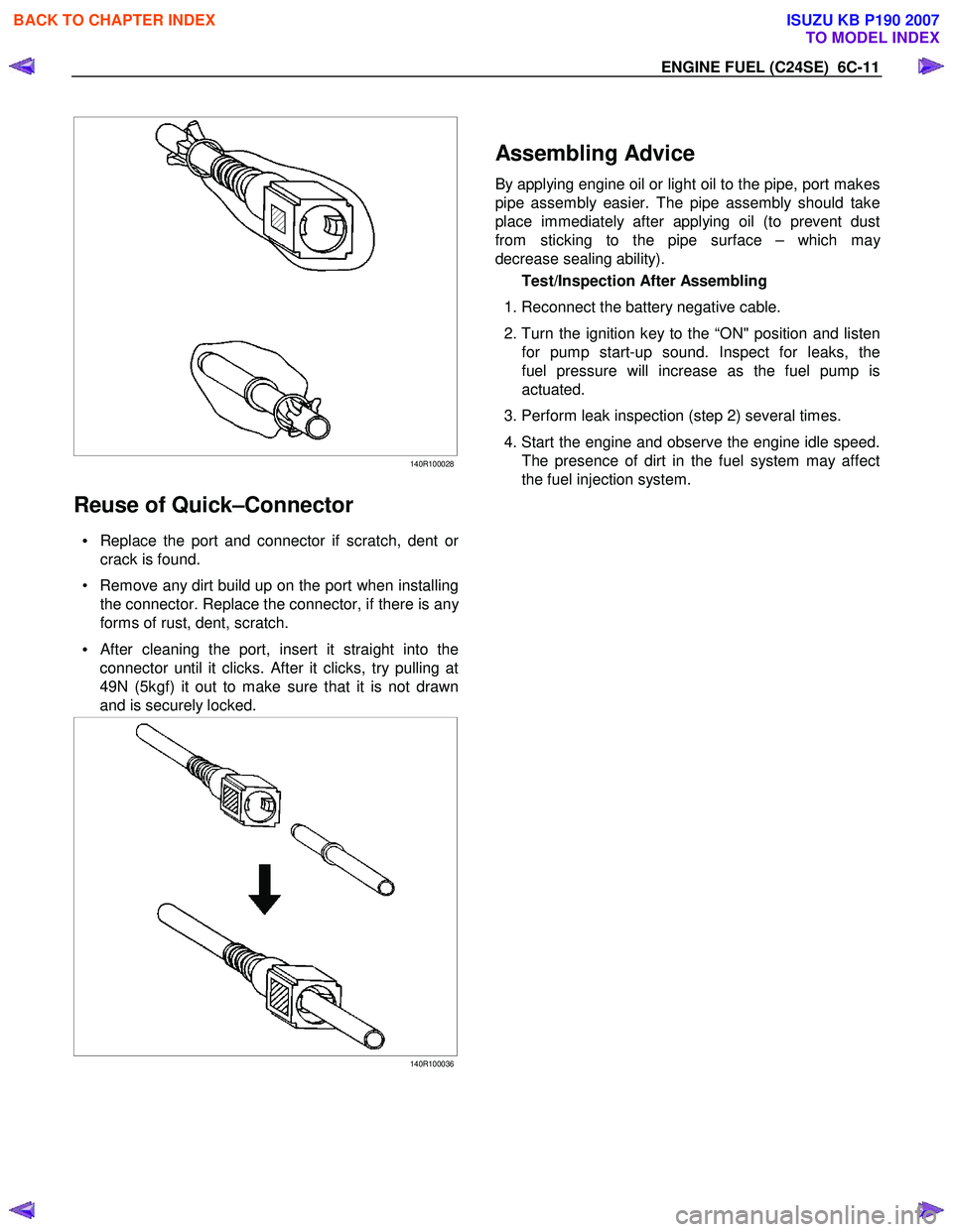
Reuse of Quick–Connector
• Replace the port and connector if scratch, dent or
crack is found.
• Remove any dirt build up on the port when installing the connector. Replace the connector, if there is an
y
forms of rust, dent, scratch.
•
After cleaning the port, insert it straight into the
connector until it clicks. After it clicks, try pulling at
49N (5kgf) it out to make sure that it is not drawn
and is securely locked.
140R100036
Assembling Advice
By applying engine oil or light oil to the pipe, port makes
pipe assembly easier. The pipe assembly should take
place immediately after applying oil (to prevent dust
from sticking to the pipe surface – which ma
y
decrease sealing ability).
Test/Inspection After Assembling
1. Reconnect the battery negative cable.
2. Turn the ignition key to the “ON" position and listen
for pump start-up sound. Inspect for leaks, the
fuel pressure will increase as the fuel pump is
actuated.
3. Perform leak inspection (step 2) several times.
4. Start the engine and observe the engine idle speed.
The presence of dirt in the fuel system may affect
the fuel injection system.
BACK TO CHAPTER INDEX
TO MODEL INDEX
ISUZU KB P190 2007
Page 2130 of 6020
6C-12 ENGINE FUEL (C24SE)
Fuel Pump Relay
General Description
In order to control the fuel pump and sender assembly
(FPAS) operation, the FPAS relay is provided. W hen
the starter switch is turned to “ON" position, the FPAS
relay operates the FPAS for 2 seconds.
W hen it is turned to “START" position, the Engine
Control Module receives the reference pulse from the
Ignition Control Module and it operates the relay, again
causing the FPAS to feed fuel.
BACK TO CHAPTER INDEX
TO MODEL INDEX
ISUZU KB P190 2007