2007 ISUZU KB P190 lights
[x] Cancel search: lightsPage 4378 of 6020
7A2-94 TRANSMISSION CONTROL SYSTEM (JR405E)
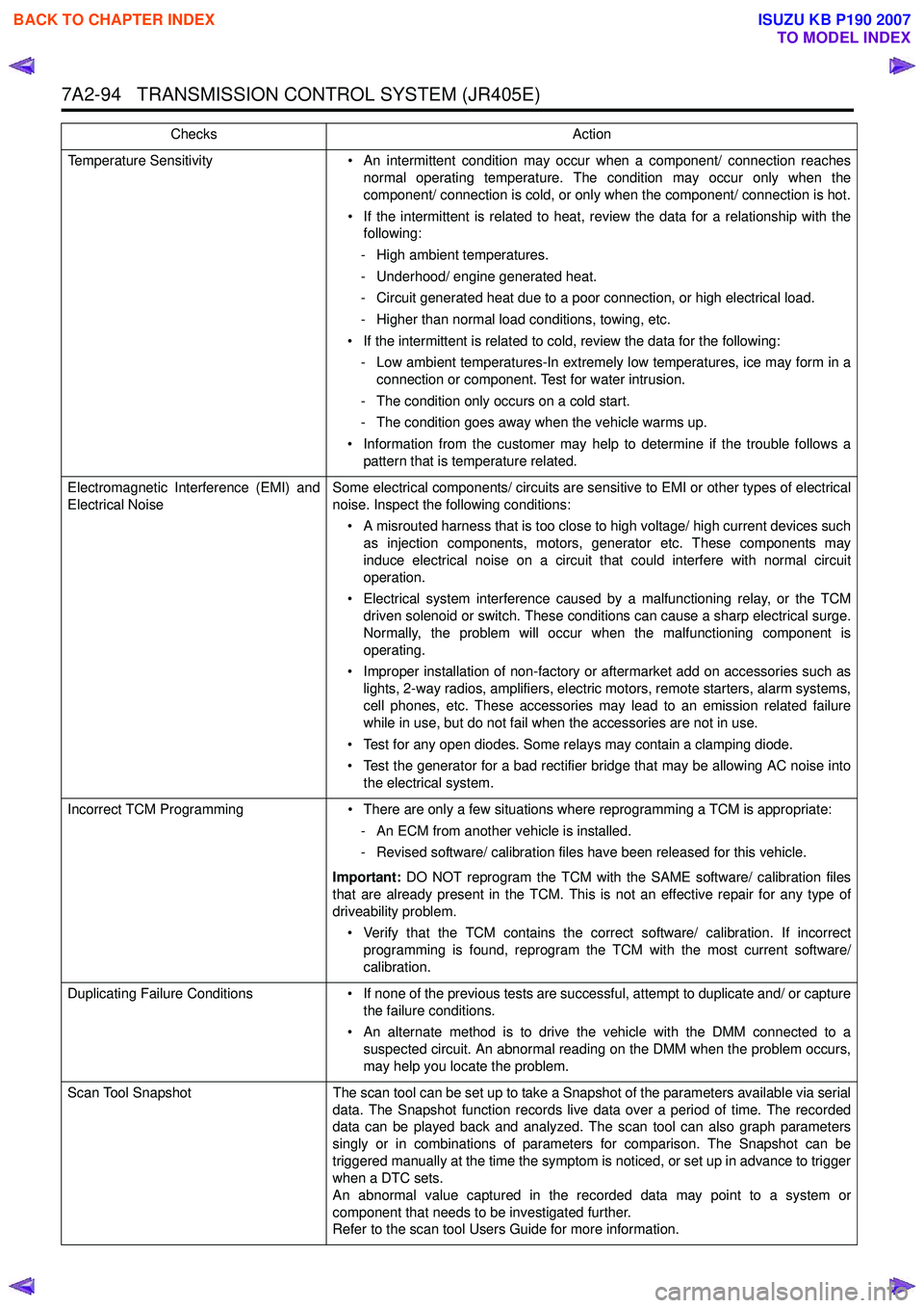
Temperature Sensitivity• An intermittent condition may occur when a component/ connection reaches
normal operating temperature. The condition may occur only when the
component/ connection is cold, or only when the component/ connection is hot.
• If the intermittent is related to heat, review the data for a relationship with the following:
- High ambient temperatures.
- Underhood/ engine generated heat.
- Circuit generated heat due to a poor connection, or high electrical load.
- Higher than normal load conditions, towing, etc.
• If the intermittent is related to cold, review the data for the following: - Low ambient temperatures-In extremely low temperatures, ice may form in a connection or component. Test for water intrusion.
- The condition only occurs on a cold start.
- The condition goes away when the vehicle warms up.
• Information from the customer may help to determine if the trouble follows a pattern that is temperature related.
Electromagnetic Interference (EMI) and
Electrical Noise Some electrical components/ circuits are sensitive to EMI or other types of electrical
noise. Inspect the following conditions:
• A misrouted harness that is too close to high voltage/ high current devices such as injection components, motors, generator etc. These components may
induce electrical noise on a circuit that could interfere with normal circuit
operation.
• Electrical system interference caused by a malfunctioning relay, or the TCM driven solenoid or switch. These conditions can cause a sharp electrical surge.
Normally, the problem will occur when the malfunctioning component is
operating.
• Improper installation of non-factory or aftermarket add on accessories such as lights, 2-way radios, amplifiers, electric motors, remote starters, alarm systems,
cell phones, etc. These accessories may lead to an emission related failure
while in use, but do not fail when the accessories are not in use.
• Test for any open diodes. Some relays may contain a clamping diode.
• Test the generator for a bad rectifier bridge that may be allowing AC noise into the electrical system.
Incorrect TCM Programming • There are only a few situations where reprogramming a TCM is appropriate:
- An ECM from another vehicle is installed.
- Revised software/ calibration files have been released for this vehicle.
Important: DO NOT reprogram the TCM with the SAME software/ calibration files
that are already present in the TCM. This is not an effective repair for any type of
driveability problem.
• Verify that the TCM contains the correct software/ calibration. If incorrect programming is found, reprogram the TCM with the most current software/
calibration.
Duplicating Failure Conditions • If none of the previous tests are successful, attempt to duplicate and/ or capture
the failure conditions.
• An alternate method is to drive the vehicle with the DMM connected to a suspected circuit. An abnormal reading on the DMM when the problem occurs,
may help you locate the problem.
Scan Tool Snapshot The scan tool can be set up to take a Snapshot of the parameters available via serial
data. The Snapshot function records live data over a period of time. The recorded
data can be played back and analyzed. The scan tool can also graph parameters
singly or in combinations of parameters for comparison. The Snapshot can be
triggered manually at the time the symptom is noticed, or set up in advance to trigger
when a DTC sets.
An abnormal value captured in the recorded data may point to a system or
component that needs to be investigated further.
Refer to the scan tool Users Guide for more information.
Checks
Action
BACK TO CHAPTER INDEX
TO MODEL INDEX
ISUZU KB P190 2007
Page 4424 of 6020
7A2-140 TRANSMISSION CONTROL SYSTEM (JR405E)
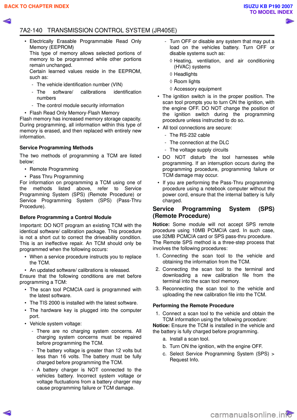
• Electrically Erasable Programmable Read OnlyMemory (EEPROM)
This type of memory allows selected portions of
memory to be programmed while other portions
remain unchanged.
Certain learned values reside in the EEPROM,
such as:
- The vehicle identification number (VIN)
- The software/ calibrations identification numbers
- The control module security information
• Flash Read Only Memory-Flash Memory
Flash memory has increased memory storage capacity.
During programming, all information within this type of
memory is erased, and then replaced with entirely new
information.
Service Programming Methods
The two methods of programming a TCM are listed
below:
• Remote Programming
• Pass Thru Programming
For information on programming a TCM using one of
the methods listed above, refer to Service
Programming System (SPS) (Remote Procedure) or
Service Programming System (SPS) (Pass-Thru
Procedure).
Before Programming a Control Module
Important: DO NOT program an existing TCM with the
identical software/ calibration package. This procedure
is not a short cut to correct the driveability condition.
This is an ineffective repair. An TCM should only be
programmed when the following occurs:
• When a service procedure instructs you to replace the TCM.
• An updated software/ calibrations is released.
Ensure that the following conditions are met before
programming a TCM:
• The scan tool PCMCIA card is programmed with the latest software.
• The TIS 2000 is installed with the latest software.
• The hardware key is plugged into the computer port.
• Vehicle system voltage:
- There are no charging system concerns. Allcharging system concerns must be repaired
before programming the TCM.
- The battery voltage is greater than 12 volts but less than 16 volts. The battery must be fully
charged before programming the TCM.
- A battery charger is NOT connected to the vehicles battery. Incorrect system voltage or
voltage fluctuations from a battery charger may
cause programming failure or TCM damage. - Turn OFF or disable any system that may put a
load on the vehicles battery. Turn OFF or
disable systems such as:
◊ Heating, ventilation, and air conditioning
(HVAC) systems
◊ Headlights
◊ Room lights
◊ Accessory equipment
• The ignition switch is in the proper position. The scan tool prompts you to turn ON the ignition, with
the engine OFF. DO NOT change the position of
the ignition switch during the programming
procedure unless instructed to do so.
• All tool connections are secure:
- The RS-232 cable
- The connection at the DLC
- The voltage supply circuits
• DO NOT disturb the tool harnesses while programming. If an interruption occurs during the
programming procedure, programming failure or
TCM damage may occur.
• If you are performing the Pass-Thru programming procedure using a notebook computer without the
power cord, ensure that the internal battery is fully
charged.
Service Programming System (SPS)
(Remote Procedure)
Notice: Some module will not accept SPS remote
procedure using 10MB PCMCIA card. In such case,
use 32MB PCMCIA card or SPS pass-thru procedure.
The Remote SPS method is a three-step process that
involves the following procedures:
1. Connecting the scan tool to the vehicle and obtaining the information from the TCM.
2. Connecting the scan tool to the terminal and downloading a new calibration file from the
terminal into the scan tool memory.
3. Reconnecting the scan tool to the vehicle and uploading the new calibration file into the TCM.
Performing the Remote Procedure 1. Connect a scan tool to the vehicle and obtain the TCM information using the following procedure:
Notice: Ensure the TCM is installed in the vehicle and
the battery is fully charged before programming.
a. Install a scan tool.
b. Turn ON the ignition, with the engine OFF.
c. Select Service Programming System (SPS) > Request Info.
BACK TO CHAPTER INDEX
TO MODEL INDEX
ISUZU KB P190 2007
Page 4925 of 6020
TRANSFER CONTROL SYSTEM 7D1-51
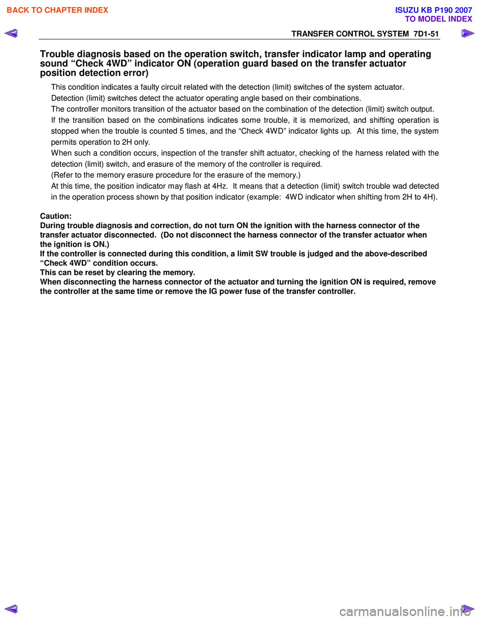
Trouble diagnosis based on the operation switch, transfer indicator lamp and operating
sound “Check 4WD” indicator ON (operation guard based on the transfer actuator
position detection error)
This condition indicates a faulty circuit related with the detection (limit) switches of the system actuator.
Detection (limit) switches detect the actuator operating angle based on their combinations.
The controller monitors transition of the actuator based on the combination of the detection (limit) switch output.
If the transition based on the combinations indicates some trouble, it is memorized, and shifting operation is
stopped when the trouble is counted 5 times, and the “Check 4W D” indicator lights up. At this time, the system
permits operation to 2H only.
W hen such a condition occurs, inspection of the transfer shift actuator, checking of the harness related with the
detection (limit) switch, and erasure of the memory of the controller is required.
(Refer to the memory erasure procedure for the erasure of the memory.)
At this time, the position indicator may flash at 4Hz. It means that a detection (limit) switch trouble wad detected
in the operation process shown by that position indicator (example: 4W D indicator when shifting from 2H to 4H).
Caution:
During trouble diagnosis and correction, do not turn ON the ignition with the harness connector of the
transfer actuator disconnected. (Do not disconnect the harness connector of the transfer actuator when
the ignition is ON.)
If the controller is connected during this condition, a limit SW trouble is judged and the above-described
“Check 4WD” condition occurs.
This can be reset by clearing the memory.
When disconnecting the harness connector of the actuator and turning the ignition ON is required, remove
the controller at the same time or remove the IG power fuse of the transfer controller.
BACK TO CHAPTER INDEX
TO MODEL INDEX
ISUZU KB P190 2007
Page 4928 of 6020
7D1-54 TRANSFER CONTROL SYSTEM
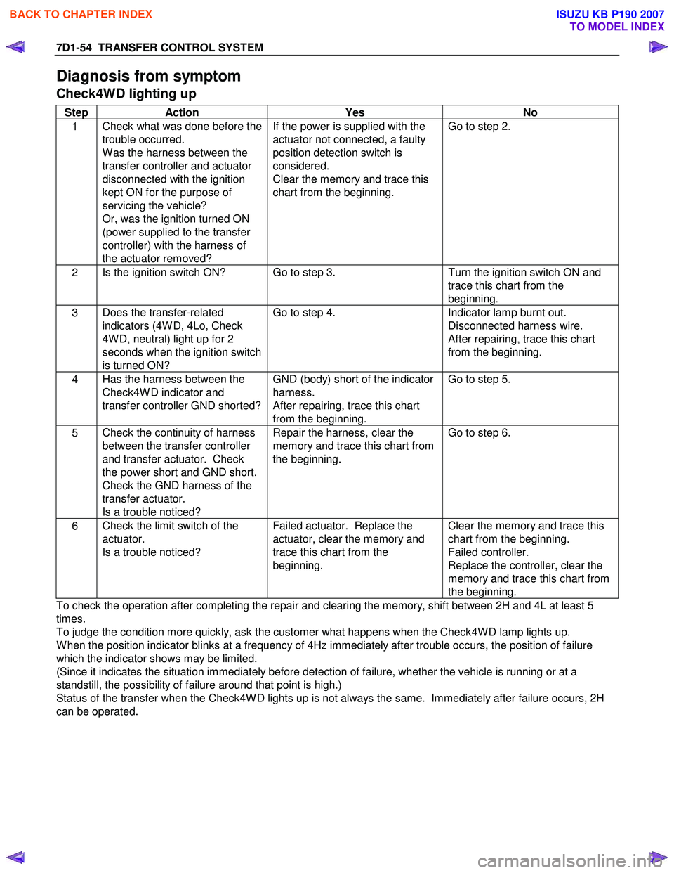
Diagnosis from symptom
Check4WD lighting up
Step Action Yes No
1 Check what was done before the
trouble occurred.
W as the harness between the
transfer controller and actuator
disconnected with the ignition
kept ON for the purpose of
servicing the vehicle?
Or, was the ignition turned ON
(power supplied to the transfer
controller) with the harness of
the actuator removed? If the power is supplied with the
actuator not connected, a faulty
position detection switch is
considered.
Clear the memory and trace this
chart from the beginning. Go to step 2.
2
Is the ignition switch ON? Go to step 3.
Turn the ignition switch ON and
trace this chart from the
beginning.
3 Does the transfer-related
indicators (4W D, 4Lo, Check
4W D, neutral) light up for 2
seconds when the ignition switch
is turned ON? Go to step 4.
Indicator lamp burnt out.
Disconnected harness wire.
After repairing, trace this chart
from the beginning.
4 Has the harness between the
Check4W D indicator and
transfer controller GND shorted? GND (body) short of the indicator
harness.
After repairing, trace this chart
from the beginning. Go to step 5.
5
Check the continuity of harness
between the transfer controller
and transfer actuator. Check
the power short and GND short.
Check the GND harness of the
transfer actuator.
Is a trouble noticed? Repair the harness, clear the
memory and trace this chart from
the beginning. Go to step 6.
6
Check the limit switch of the
actuator.
Is a trouble noticed? Failed actuator. Replace the
actuator, clear the memory and
trace this chart from the
beginning. Clear the memory and trace this
chart from the beginning.
Failed controller.
Replace the controller, clear the
memory and trace this chart from
the beginning.
To check the operation after completing the repair and clearing the memory, shift between 2H and 4L at least 5
times.
To judge the condition more quickly, ask the customer what happens when the Check4W D lamp lights up.
W hen the position indicator blinks at a frequency of 4Hz immediately after trouble occurs, the position of failure
which the indicator shows may be limited.
(Since it indicates the situation immediately before detection of failure, whether the vehicle is running or at a
standstill, the possibility of failure around that point is high.)
Status of the transfer when the Check4W D lights up is not always the same. Immediately after failure occurs, 2H
can be operated.
BACK TO CHAPTER INDEX
TO MODEL INDEX
ISUZU KB P190 2007
Page 4934 of 6020
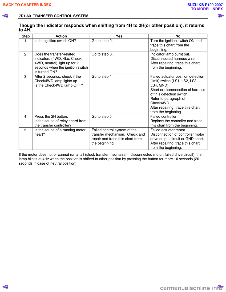
7D1-60 TRANSFER CONTROL SYSTEM
Though the indicator responds when shifting from 4H to 2H(or other position), it returns
to 4H.
Step Action Yes No
1 Is the ignition switch ON? Go to step 2.
Turn the ignition switch ON and
trace this chart from the
beginning.
2 Does the transfer-related
indicators (4W D, 4Lo, Check
4W D, neutral) light up for 2
seconds when the ignition switch
is turned ON? Go to step 3.
Indicator lamp burnt out.
Disconnected harness wire.
After repairing, trace this chart
from the beginning.
3 After 2 seconds, check if the
Check4W D lamp lights up.
Is the Check4W D lamp OFF? Go to step 4.
Failed actuator position detection
(limit) switch (LS1, LS2, LS3,
LS4, GND).
Short or disconnection of harness
of this detection switch.
Refer to paragraph of
Check4W D.
After repairing, trace this chart
from the beginning.
4 Press the 2H button.
Is the sound of relay heard from
the transfer controller? Go to step 5.
Failed controller.
Replace the controller and trace
this chart from the beginning.
5 Is the sound of a running motor
heart? Failed control system of the
transfer mechanism. Check and
repair and trace this chart from
the beginning. Failed actuator motor.
Disconnection of controller motor
drive output circuit or GND short.
After repairing, trace this chart
from the beginning.
If the motor does not or cannot run at all (stuck transfer mechanism, disconnected motor, failed drive circuit), the
lamp blinks at 4Hz when the position is shifted to other position by pressing the button for more 10 seconds (20
seconds in case of neutral position).
BACK TO CHAPTER INDEX
TO MODEL INDEX
ISUZU KB P190 2007
Page 4958 of 6020
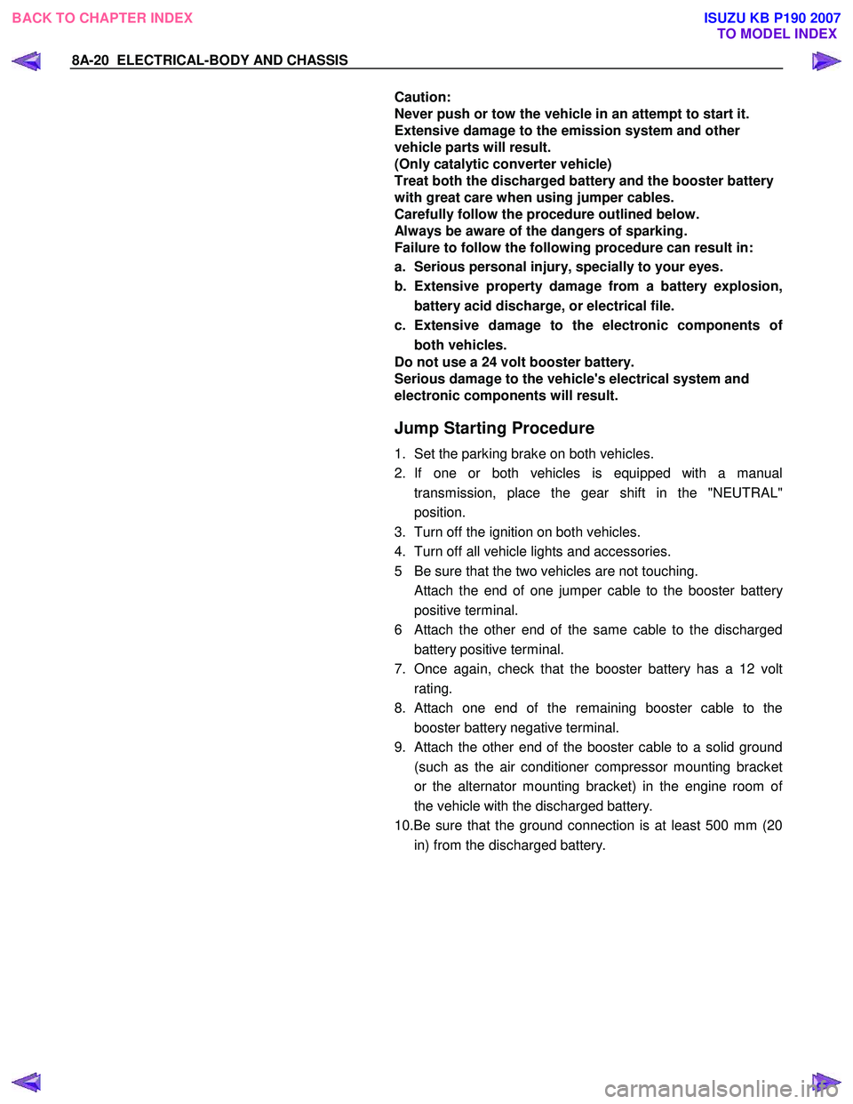
8A-20 ELECTRICAL-BODY AND CHASSIS
Caution:
Never push or tow the vehicle in an attempt to start it.
Extensive damage to the emission system and other
vehicle parts will result.
(Only catalytic converter vehicle)
Treat both the discharged battery and the booster battery
with great care when using jumper cables.
Carefully follow the procedure outlined below.
Always be aware of the dangers of sparking.
Failure to follow the following procedure can result in:
a. Serious personal injury, specially to your eyes.
b. Extensive property damage from a battery explosion, battery acid discharge, or electrical file.
c. Extensive damage to the electronic components o
f
both vehicles.
Do not use a 24 volt booster battery.
Serious damage to the vehicle's electrical system and
electronic components will result.
Jump Starting Procedure
1. Set the parking brake on both vehicles.
2. If one or both vehicles is equipped with a manual transmission, place the gear shift in the "NEUTRAL"
position.
3. Turn off the ignition on both vehicles.
4. Turn off all vehicle lights and accessories.
5 Be sure that the two vehicles are not touching.
Attach the end of one jumper cable to the booster battery
positive terminal.
6
Attach the other end of the same cable to the discharged
battery positive terminal.
7. Once again, check that the booster battery has a 12 volt rating.
8.
Attach one end of the remaining booster cable to the
booster battery negative terminal.
9.
Attach the other end of the booster cable to a solid ground
(such as the air conditioner compressor mounting bracket
or the alternator mounting bracket) in the engine room o
f
the vehicle with the discharged battery.
10.Be sure that the ground connection is at least 500 mm (20 in) from the discharged battery.
BACK TO CHAPTER INDEX TO MODEL INDEXISUZU KB P190 2007
Page 4970 of 6020
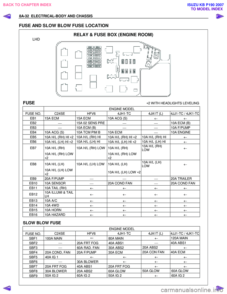
8A-32 ELECTRICAL-BODY AND CHASSIS
FUSE AND SLOW BLOW FUSE LOCATION
RELAY & FUSE BOX (ENGINE ROOM)
LHD
FUSE ∗2 W ITH HEADLIGHTS LEVELING
ENGINE MODEL
FUSE NO. C24SE HFV6 4JH1-TC 4JA1T (L) 4JJ1-TC / 4JK1-TC
EB1 15A ECM 15A ECM 10A ACG (S)
← ←
EB2
15A 02 SENS PRE
10A ECM (B)
EB3
10A ECM (B)
10A F/PUMP
EB4 10A ACG (S) 10A TCM PIM B 10A ECM
10A ENGINE
EB5
10A H/L (RH) HI ∗2 10A H/L (RH) HI
10A H/L (RH) HI ∗2 10A H/L (RH) HI
←
EB6
10A H/L (LH) HI ∗2 10A H/L (LH) HI
10A H/L (LH) HI ∗2 10A H/L (LH) HI
←
EB7 10A H/L (RH) 10A H/L (RH) LOW 10A H/L (RH) 10A H/L (RH)
LOW ←
10A H/L (RH) LOW
∗ 2
10A H/L (RH) LOW
∗ 2
EB8 10A H/L (LH) 10A H/L (LH) LOW 10A H/L (LH)
10A H/L (LH)
LOW ←
10A H/L (LH) LOW
∗ 2
10A H/L (LH) LOW ∗2
EB9 20A F/PUMP
20A TRAILER
EB10 10A SENSOR
20A COND FAN
20A COND FAN
EB11 10A TAIL (RH)
← ← ← ←
EB12 10A ILLUMI & TAIL
LH ←
← ← ←
EB13 10A A/C
← ← ← ←
EB14 10A 4W D
← ← ← ←
EB15 10A HORN
← ← ← ←
EB16 10A HAZARD
← ← ← ←
SLOW BLOW FUSE
ENGINE MODEL
FUSE NO. C24SE
HFV6 4JH1-TC 4JA1T (L) 4JJ1-TC / 4JK1-TC
SBF1 100A MAIN ←
80A MAIN ←
120A MAIN
SBF2
20A FRT FOG 40A ABS1
40A ABS1
SBF3
60A RAD. FAN 30A ABS2 20A ABS2
←
SBF4 20A COND, FAN 20A F/PUMP 30A ECM 20A CON FAN 40A ECM
SBF5 40A IG 1
←
← ←
←
SBF6
30A BLOW ER ←
←
←
SBF7 20A FRT FOG 40A ABS1 20A FRT FOG ←
←
SBF8 30A BLOW ER 20A ABS2 60A GLOW 50A GLOW 60A GLOW
SBF9 50A IG 2
60A IG 2 50A IG 2
← 60A IG 2
BACK TO CHAPTER INDEX
TO MODEL INDEXISUZU KB P190 2007
Page 5090 of 6020
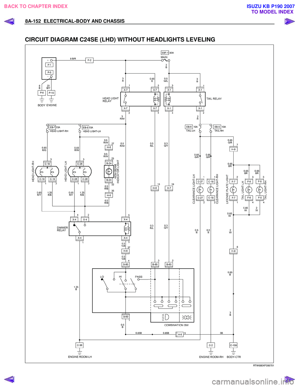
8A-152 ELECTRICAL-BODY AND CHASSIS
CIRCUIT DIAGRAM C24SE (LHD) WITHOUT HEADLIGHTS LEVELING
RTW 680XF006701
BACK TO CHAPTER INDEX
TO MODEL INDEXISUZU KB P190 2007