Page 5091 of 6020
ELECTRICAL-BODY AND CHASSIS 8A-153
CIRCUIT DIAGRAM C24SE (LHD) WITH HEADLIGHTS LEVELING
RTW 680XF006801
BACK TO CHAPTER INDEX
TO MODEL INDEXISUZU KB P190 2007
Page 5098 of 6020
8A-160 ELECTRICAL-BODY AND CHASSIS
TROUBLE SHOOTING
HEADLIGHT
1. Both the headlights (high and low beam) do not light
Checkpoint Trouble Cause Countermeasure
Repair the wiring
Poor ground point contact
NG
Repair open circuit or
connector contact
Repair open circuit
Repair or replace the
combination switch
Voltage between 1
B60 -
ground
Open circuit between lighting
relay and lighting switch
Open circuit between battery
positiv e terminal and lighting
relay
Combination switch continuity
Poor switch contact or sw
faulty
Voltage between
5
X6 - ground and
2
X6 - ground
Reinstall or replace the
lighting relay
Lighting relay
Poor relay contact or relay
faulty
NG
NG
NG
NG
OK
OK
OK
OK
Ground point contact (C2),
(C36)
Repair open circuit
W iring continuity between
B60 - C2
Open circuit
NG
OK
BACK TO CHAPTER INDEX
TO MODEL INDEXISUZU KB P190 2007
Page 5099 of 6020

ELECTRICAL-BODY AND CHASSIS 8A-161
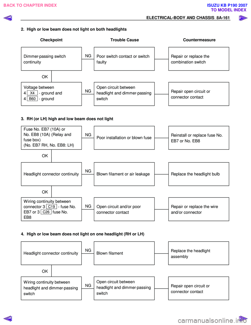
2. High or low beam does not light on both headlights
Checkpoint Trouble Cause Countermeasure
Repair or replace the
combination switch
Dimmer ⋅passing switch
continuity
Poor switch contact or switch
faulty
NG
Repair open circuit or
connector contact
Voltage between
4
X4 - ground and
4
B60 - ground
Open circuit between
headlight and dimmer ⋅passing
switch
NG
OK
3. RH (or LH) high and low beam does not light
Replace the headlight bulb
Headlight connector continuity
Blown filament or air leakage
NG
Repair or replace the wire
and/or connector
W iring continuity between
connector 3
C19 - fuse No.
EB7 or 3
C26 fuse No.
EB8
Open circuit and/or poor
connector contact
NG
OK
Reinstall or replace fuse No.
EB7 or No. EB8
Fuse No. EB7 (10A) or
No. EB8 (10A) (Relay and
fuse box)
(No. EB7 RH, No. EB8: LH)
Poor installation or blown fuse
NG
OK
4. High or low beam does not light on one headlight (RH or LH)
Replace the headlight
assemblyHeadlight connector continuityBlown filament
NG
Repair open circuit or
connector contactW iring continuity between
headlight and dimmer ⋅passing
switchOpen circuit between
headlight and dimmer ⋅passing
switch
NG
OK
BACK TO CHAPTER INDEX
TO MODEL INDEXISUZU KB P190 2007
Page 5102 of 6020
8A-164 ELECTRICAL-BODY AND CHASSIS
TAIL LIGHT, LICENSE PLATE LIGHT, CLEARANCE LIGHT
1. All lights do not light
Checkpoint Trouble Cause Countermeasure
Repair or replace the
combination switch
Lighting switch continuity
between connector
2
B60 - 1 B60
Poor switch point or connector
contact
NG
Reinstall or replace the tail
relay
Tail relay
Poor relay contact or relay
faulty
NG
OK
Reinstall or replace the fuse
No. EB12 (LH), EB11 (RH)
Fuse No. EB12 (LH) or EB11
(RH) (10A, Relay and fuse
box)
Poor fuse contact or blown
NG
OK
2. Tail light does not light
Replace the bulb or repair
connector contact
Tail light bulb continuity
Bulb burned out or poor
connector contact
NG
Repair open circuit or
connector contact
Continuity between connector
3
F5 - 4 F5 (RH)
or 3
F6 - 4 F6 (LH)
Open circuit or poor connector
contact
NG
OK
BACK TO CHAPTER INDEX
TO MODEL INDEXISUZU KB P190 2007
Page 5111 of 6020

ELECTRICAL-BODY AND CHASSIS 8A-173
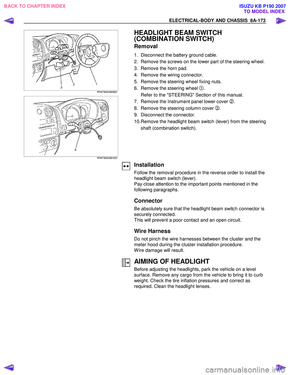
RTW 780SH000901
RTW 780SH001001
HEADLIGHT BEAM SWITCH
(COMBINATION SWITCH)
Removal
1. Disconnect the battery ground cable.
2. Remove the screws on the lower part of the steering wheel.
3. Remove the horn pad.
4. Remove the wiring connector.
5. Remove the steering wheel fixing nuts.
6. Remove the steering wheel
1.
Refer to the "STEERING" Section of this manual.
7. Remove the Instrument panel lower cover
2.
8. Remove the steering column cover
3.
9. Disconnect the connector.
10. Remove the headlight beam switch (lever) from the steering shaft (combination switch).
Installation
Follow the removal procedure in the reverse order to install the
headlight beam switch (lever).
Pay close attention to the important points mentioned in the
following paragraphs.
Connector
Be absolutely sure that the headlight beam switch connector is
securely connected.
This will prevent a poor contact and an open circuit.
Wire Harness
Do not pinch the wire harnesses between the cluster and the
meter hood during the cluster installation procedure.
W ire damage will result.
AIMING OF HEADLIGHT
Before adjusting the headlights, park the vehicle on a level
surface. Remove any cargo from the vehicle to bring it to curb
weight. Check the tire inflation pressures and correct as
required. Clean the headlight lenses.
BACK TO CHAPTER INDEX TO MODEL INDEXISUZU KB P190 2007
Page 5307 of 6020

ELECTRICAL-BODY AND CHASSIS 8A-369
Low Fuel Indicator Light
1. Disconnect the fuel gauge unit wire connector.
2. Turn the key switch on. Check that the bulb lights.
If operation is not correct, remove and check the bulb or circuit.
or If check whether low fuel turns on fuel input (B-24) at the
time of open and key on.
∗ meter is check at low fuel
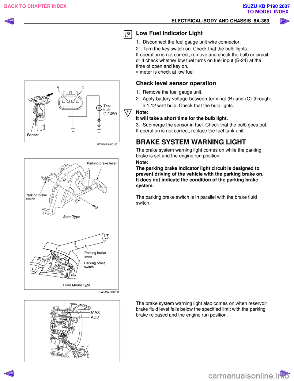
RTW 78ASH001501
Check level sensor operation
1. Remove the fuel gauge unit.
2. Apply battery voltage between terminal (B) and (C) through a 1.12 watt bulb. Check that the bulb lights.
Note:
It will take a short time for the bulb light.
3. Submerge the sensor in fuel. Check that the bulb goes out.
If operation is not correct, replace the fuel tank unit.
BRAKE SYSTEM WARNING LIGHT
The brake system warning light comes on while the parking
brake is set and the engine run position.
RTW 48AMH000101
Note:
The parking brake indicator light circuit is designed to
prevent driving of the vehicle with the parking brake on.
It does not indicate the condition of the parking brake
system.
The parking brake switch is in parallel with the brake fluid
switch.
The brake system warning light also comes on when reservoir
brake fluid level falls below the specified limit with the parking
brake released and the engine run position.
BACK TO CHAPTER INDEX TO MODEL INDEXISUZU KB P190 2007
Page 5490 of 6020
8A-552 ELECTRICAL-BODY AND CHASSIS
ID Code Check
Numbers of registered ID code shall be checked in this
mode.
Step Action Yes No
1 NOTE: Make sure that the all the doors are closed.
Is the action complete? Go to Step 2
2 Insert the ignition key into the key lock twice, and then re-
inserted.
NOTE: This step must be carried out within five seconds.
Count the number of times the hazard lights flash on and off.
This number is equal to the number of registrations.
Is the action complete? Go to Step 1 Go to Step 1
RUW 59DLF000101
BACK TO CHAPTER INDEX TO MODEL INDEXISUZU KB P190 2007
Page 5523 of 6020
ELECTRICAL-BODY AND CHASSIS 8A-585
RTW 38DSH001701
Turn Signal Test
Check the turn signal lamp lights up by operation of
Tech-2.
1. Turn the key “OFF”.
2. Turn the key “ON”.
3. Check the display and test menu.
4. Operate the Tech-2.
060R200289
Programming
Erase Remove Key
To erase remove control key code in the control unit.
1. Check the display of Tech-2 and press “Confirm”
key.
RTW 38DSH001001
2. Enter security code.
3. Press “Not Okay” or “Okay” key.
BACK TO CHAPTER INDEX TO MODEL INDEXISUZU KB P190 2007