2007 ISUZU KB P190 horn
[x] Cancel search: hornPage 5181 of 6020
ELECTRICAL-BODY AND CHASSIS 8A-243
RTW 78ASH002001
A Type
RTW 78ASH002101
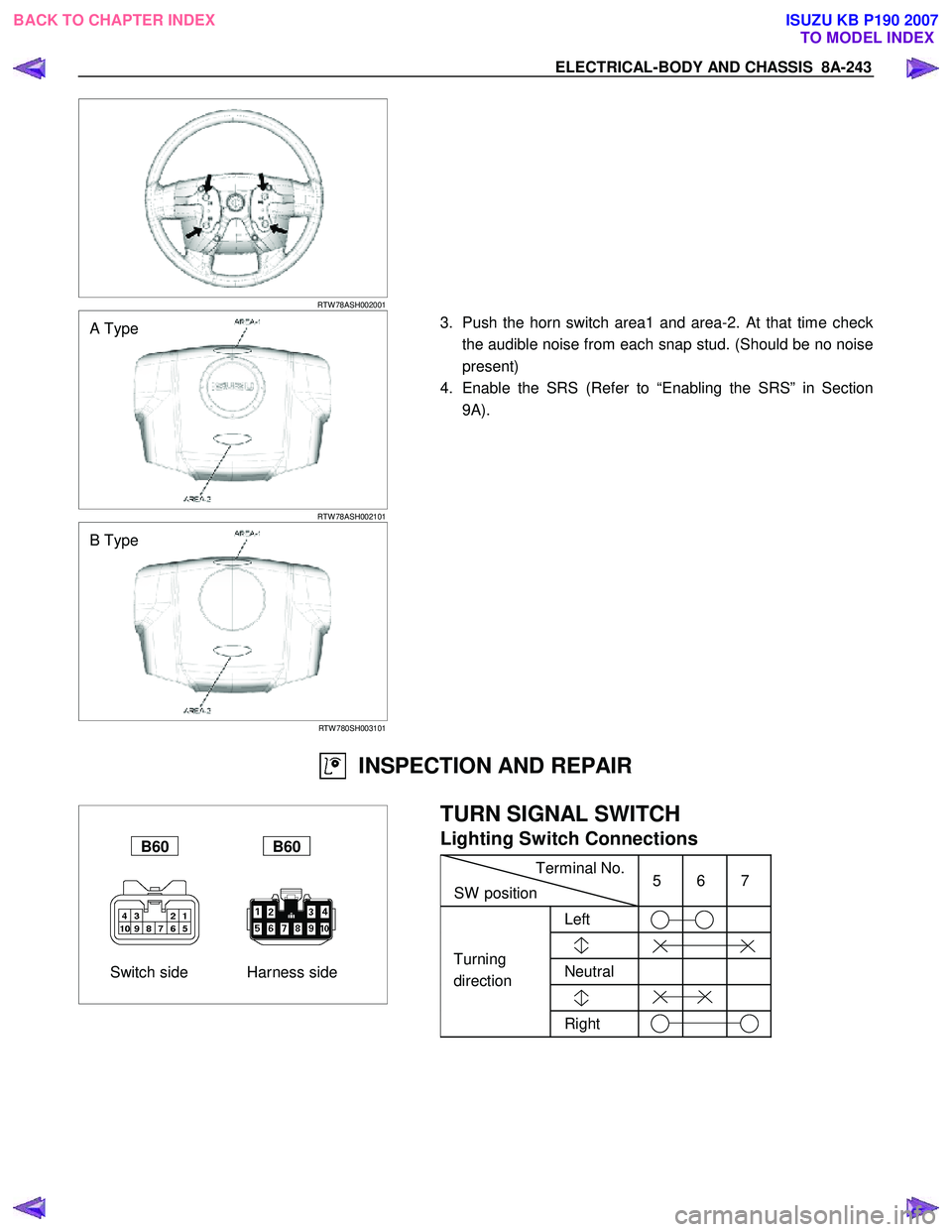
3. Push the horn switch area1 and area-2. At that time check
the audible noise from each snap stud. (Should be no noise
present)
4. Enable the SRS (Refer to “Enabling the SRS” in Section 9A).
B Type
RTW 780SH003101
INSPECTION AND REPAIR
Switch side Harness side
B60 B60
TURN SIGNAL SWITCH
Lighting Switch Connections
Terminal No.
SW position 5 6 7
Left
Neutral
Right
Turning
direction
BACK TO CHAPTER INDEX TO MODEL INDEXISUZU KB P190 2007
Page 5549 of 6020
ELECTRICAL-BODY AND CHASSIS 8A-611
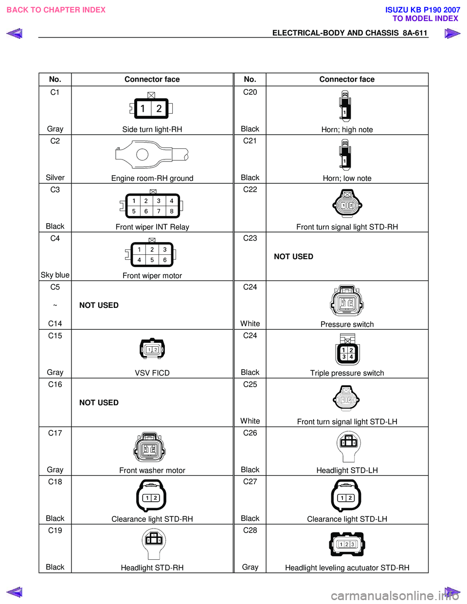
No. Connector face No. Connector face
C1
Gray
Side turn light-RH C20
BlackHorn; high note
C2
Silver
Engine room-RH ground C21
BlackHorn; low note
C3
Black
Front wiper INT Relay C22
Front turn signal light STD-RH
C4
Sky blue
Front wiper motor C23
NOT USED
C5
~
C14 NOT USED C24
White
Pressure switch
C15
Gray
VSV FICD C24
BlackTriple pressure switch
C16
NOT USED C25
White
Front turn signal light STD-LH
C17
Gray
Front washer motor C26
BlackHeadlight STD-LH
C18
Black
Clearance light STD-RH C27
BlackClearance light STD-LH
C19
Black
Headlight STD-RH C28
Gray Headlight leveling acutuator STD-RH
BACK TO CHAPTER INDEX TO MODEL INDEXISUZU KB P190 2007
Page 5552 of 6020
8A-614 ELECTRICAL-BODY AND CHASSIS
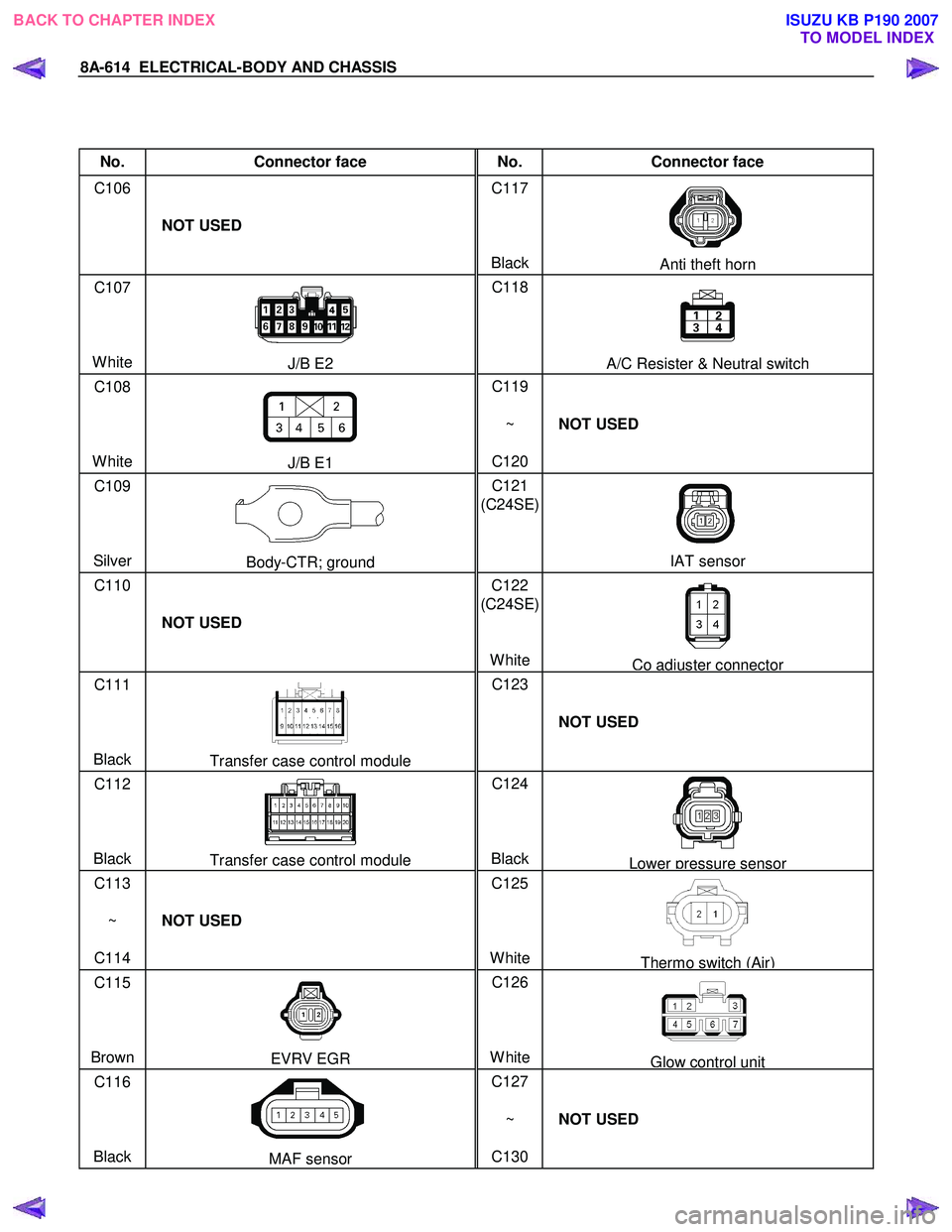
No. Connector face No. Connector face
C106
NOT USED C117
Black
Anti theft horn
C107
White
J/B E2 C118
A/C Resister & Neutral switch
C108
White
J/B E1 C119
~
C120 NOT USED
C109
Silver
Body-CTR; ground C121
(C24SE)
IAT sensor
C110
NOT USED C122
(C24SE)
White
Co adjuster connector
C111
Black
Transfer case control module C123
NOT USED
C112
Black
Transfer case control module C124
BlackLower pressure sensor
C113
~
C114 NOT USED C125
White
Thermo switch (Air)
C115
Brown
EVRV EGR C126
WhiteGlow control unit
C116
Black
MAF sensor C127
~
C130 NOT USED
BACK TO CHAPTER INDEX
TO MODEL INDEXISUZU KB P190 2007
Page 5571 of 6020
ELECTRICAL-BODY AND CHASSIS 8A-633
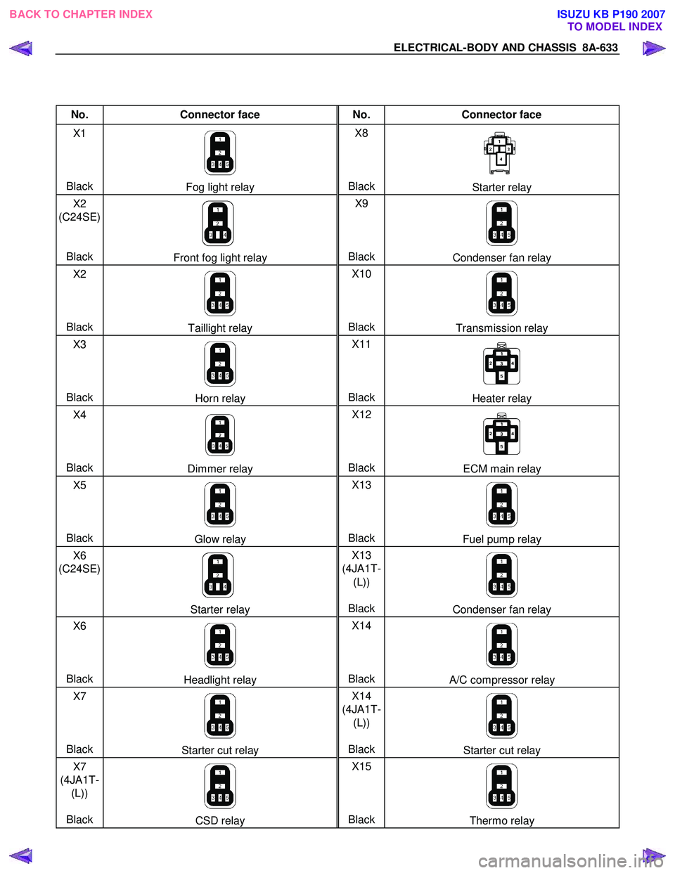
No. Connector face No. Connector face
X1
Black
Fog light relay X8
BlackStarter relay
X2
(C24SE)
Black
Front fog light relay X9
BlackCondenser fan relay
X2
Black
Taillight relay X10
BlackTransmission relay
X3
Black
Horn relay X11
BlackHeater relay
X4
Black
Dimmer relay X12
BlackECM main relay
X5
Black
Glow relay X13
BlackFuel pump relay
X6
(C24SE)
Starter relay X13
(4JA1T- (L))
BlackCondenser fan relay
X6
Black
Headlight relay X14
BlackA/C compressor relay
X7
Black
Starter cut relay X14
(4JA1T- (L))
BlackStarter cut relay
X7
(4JA1T- (L))
Black
CSD relay X15
BlackThermo relay
BACK TO CHAPTER INDEX TO MODEL INDEXISUZU KB P190 2007
Page 5955 of 6020
ANTITHEFT SYSTEM 11B-1
SECTION 11B
ANTITHEFT SYSTEM
TABLE OF CONTENTS
Service Precaution .................................................. 11B- 2
General Description ................................................ 11B- 2
Diagrams And Schematics ................................. 11B- 5 System W iring Diagrams ................................ 11B- 5
Parts Location ................................................. 11B- 6
Circuit Diagram ..............................................11B-10
Antitheft control unit (A) ...................................11B-24
Pin-outs ...........................................................11B-24
Pin-Assignment ...............................................11B-25
lmportant information on Programming..............11B-26
Tech-2 Scan Tool ...............................................11B-27 Operating Procedure .......................................11B-27
Menu ...............................................................11B-28
DTC .................................................................11B-28
Clear DTC Information ....................................11B-28
Tech-2 Data Display........................................11B-28
Actuator Test ...................................................11B-28
Programming...................................................11B-30
Tech-2 Data List ..............................................11B-35
Diagnosis............................................................11B-36 Diagnostic procedure ......................................11B-36
Clearing Diagnostic Trouble Codes ................11B-36
Verifying Vehicle Repair ..................................11B-36
Diagnostic Aids................................................11B-36
Diagnostic Trouble Code (DTC) list
For Antitheft.....................................................11B-37
Antitheft System Check ...................................11B-38
No Antitheft Lamp ...........................................11B-39
DTC13 Security code not yet programmed .....11B-40
DTC14 No remote key programmed ...............11B-41
DTC16 Door lock actuators short circuit
to ground .........................................................11B-42
DTC20 Broken wire to door lock actuators .....11B-43
DTC21 Remote key 1 with random code
out of capture range ........................................11B-44
DTC22 Remote key 2 with random code
out of capture range ........................................11B-45
DTC23 Remote key 3 with random code
out of capture range ........................................11B-46
DTC24 Remote key 4 with random code
out of capture range ........................................ 11B-47
DTC25 Remote key 5 with random code
out of capture range ........................................ 11B-48
DTC28 Input immobilizer short circuit
to ground ......................................................... 11B-49
DTC29 Broken wire to immobilizer ................. 11B-50
DTC31 Actuator driver door defect ................. 11B-51
DTC32 Actuator passenger door defect ......... 11B-52
DTC36 Broken wire to driver door................... 11B-53
DTC37 Broken wire to passenger door........... 11B-54
DTC41 Driver door Lock switch unlock
defect .............................................................. 11B-55
DTC42 Driver door Lock switch lock defect .... 11B-56
DTC43 Driver door Lock switch Super lock
defect .............................................................. 11B-57
DTC44 Passenger door Lock switch lock
defect .............................................................. 11B-58
DTC45 Passenger door Lock switch unlock
defect .............................................................. 11B-59
DTC47 Battery voltage for door lock actuators
is missing ........................................................ 11B-60
DTC50 A/D converter defect or battery
voltage less than 9 volt.................................... 11B-61
DTC51 EEPROM defect ................................. 11B-62
DTC52 EEPROM not programmed
by ISUZU ......................................................... 11B-63
DTC55 Control unit defect............................... 11B-64
DTC123 Output flasher short circuit to ground
or broken wire ................................................. 11B-65
DTC125 Output alarm horn broken wire ......... 11B-66
BACK TO CHAPTER INDEX TO MODEL INDEX
ISUZU KB P190 2007
Page 5956 of 6020
11B-2 ANTITHEFT SYSTEM
Service Precaution
WARNING: THIS VEHICLE HAS A SUPPLEMENTAL
RESTRAINT SYSTEM (SRS). REFER TO THE SRS
COMPONENT AND WIRING LOCATION VIEW IN
ORDER TO DETERMINE WHETHER YOU ARE
PERFORMING SERVICE ON OR NEAR THE SRS
COMPONENTS OR THE SRS WIRING. WHEN YOU
ARE PERFORMING SERVICE ON OR NEAR THE
SRS COMPONENTS OR THE SRS WIRING, REFER
TO THE SRS SERVICE INFORMATION. FAILURE TO
FOLLOW WARNINGS COULD RESULT IN
POSSIBLE AIR BAG DEPLOYMENT, PERSONAL
INJURY, OR OTHERWISE UNNEEDED SRS SYSTEM
REPAIRS.
CAUTION: Always use the correct fastener in the
proper location. When you replace a fastener, use
ONLY the exact part number for that application.
ISUZU will call out those fasteners that require a
replacement after removal. ISUZU will also call out
the fasteners that require thread lockers or thread
sealant. UNLESS OTHERWISE SPECIFIED, do not
use supplemental coatings (Paints, greases, or
other corrosion inhibitors) on threaded fasteners or
fastener joint interfaces. Generally, such coatings
adversely affect the fastener torque and the joint
clamping force, and may damage the fastener.
When you install fasteners, use the correct
tightening sequence and specifications. Following
these instructions can help you avoid damage to
parts and systems.
General Description
The Antitheft system consists of the four major
components which are Antitheft Control Unit (ACU),
Antitheft horn, key (remote key), and scan tool (Tech-2).
This system can be activated by a correctly
programmed key (remote key) and starter switch is set
to OFF.
This system can be deactivated by a correctly
programmed key (remote key) connected with a
correctly programmed ACU and a correctly
programmed lCU.
W hen the vehicle doors, and engine hood are locked,
the antitheft alarm system is designed to protect your
vehicle and valuables from theft.
Any attempt to forcibly open any door, the engine hood
without using the vehicle key (or remote control) will
cause the hazard lights to flash on and off and the horn
to sound intermittently. This will continue for 30 seconds
(Hazard lamp flash; For 5 minutes) before the system
automatically shuts itself off.
Please operate the door either the key lock or remote
key after closing all doors to arm the alarm system.
Miss waning will be detected when the passenger door
is opened with locked condition and then this door is
closed.
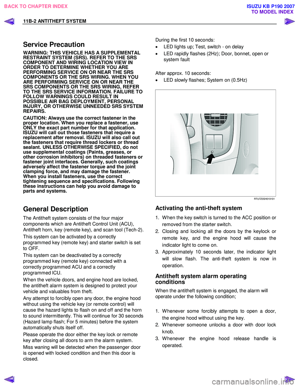
During the first 10 seconds:
• LED lights up; Test, switch - on delay
• LED rapidly flashes (2Hz); Door, bonnet, open or
system fault
After approx. 10 seconds:
• LED slowly flashes; System on (0.5Hz)
RTU7Z0SH019101
Activating the anti-theft system
1. W hen the key switch is turned to the ACC position or
removed from the starter switch.
2. Closing and locking all the doors by the keylock o
r
remote key, and the engine hood will cause the
indicator light to come on.
3. Approximately 10 seconds later, the indicator light will slow flash. The anti-theft system is now in
operation.
Antitheft system alarm operating
conditions
W hen the antitheft system is engaged, the alarm will
operate under the following condition;
1. W henever some forcibly attempts to open a door, the engine hood without using the key.
2. W henever someone unlocks a door with door lock knob.
3. W henever the engine hood release handle is operated.
BACK TO CHAPTER INDEX TO MODEL INDEX
ISUZU KB P190 2007
Page 5979 of 6020
ANTITHEFT SYSTEM 11B-25
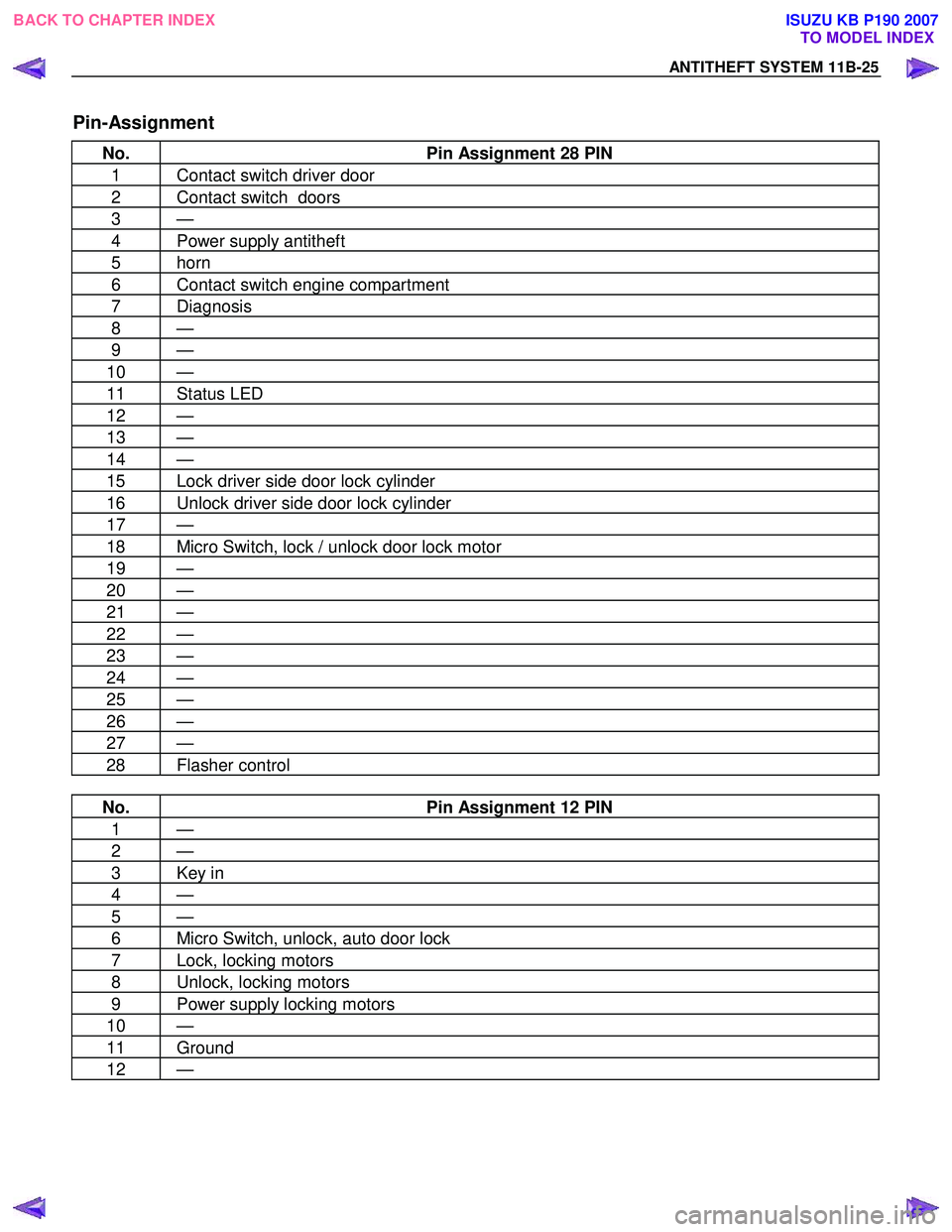
Pin-Assignment
No. Pin Assignment 28 PIN
1 Contact switch driver door
2 Contact switch doors
3 —
4 Power supply antitheft
5 horn
6 Contact switch engine compartment
7 Diagnosis
8 —
9 —
10 —
11 Status LED
12 —
13 —
14 —
15 Lock driver side door lock cylinder
16 Unlock driver side door lock cylinder
17 —
18 Micro Switch, lock / unlock door lock motor
19 —
20 —
21 —
22 —
23 —
24 —
25 —
26 —
27 —
28 Flasher control
No. Pin Assignment 12 PIN
1 —
2 —
3 Key in
4 —
5 —
6 Micro Switch, unlock, auto door lock
7 Lock, locking motors
8 Unlock, locking motors
9 Power supply locking motors
10 —
11 Ground
12 —
BACK TO CHAPTER INDEX
TO MODEL INDEX
ISUZU KB P190 2007
Page 5982 of 6020
11B-28 ANTITHEFT SYSTEM
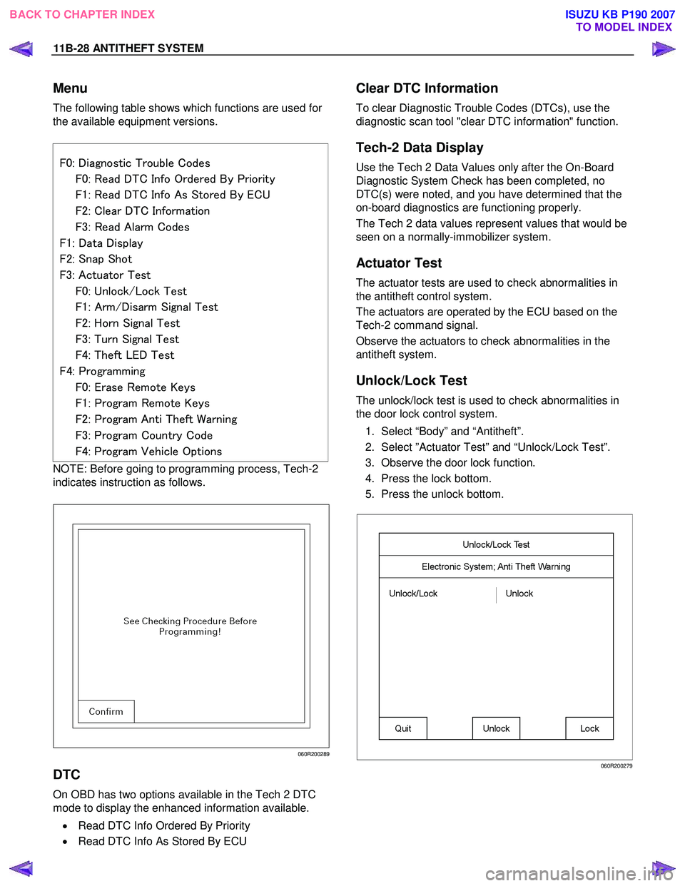
Menu
The following table shows which functions are used for
the available equipment versions.
F0: Diagnostic Trouble Codes
F0: Read DTC Info Ordered By Priority
F1: Read DTC Info As Stored By ECU
F2: Clear DTC Information
F3: Read Alarm Codes
F1: Data Display
F2: Snap Shot
F3: Actuator Test
F0: Unlock/Lock Test
F1: Arm/Disarm Signal Test
F2: Horn Signal Test
F3: Turn Signal Test
F4: Theft LED Test
F4: Programming
F0: Erase Remote Keys
F1: Program Remote Keys
F2: Program Anti Theft Warning
F3: Program Country Code
F4: Program Vehicle Options
NOTE: Before going to programming process, Tech-2
indicates instruction as follows.
060R200289
DTC
On OBD has two options available in the Tech 2 DTC
mode to display the enhanced information available.
• Read DTC Info Ordered By Priority
• Read DTC Info As Stored By ECU
Clear DTC Information
To clear Diagnostic Trouble Codes (DTCs), use the
diagnostic scan tool "clear DTC information" function.
Tech-2 Data Display
Use the Tech 2 Data Values only after the On-Board
Diagnostic System Check has been completed, no
DTC(s) were noted, and you have determined that the
on-board diagnostics are functioning properly.
The Tech 2 data values represent values that would be
seen on a normally-immobilizer system.
Actuator Test
The actuator tests are used to check abnormalities in
the antitheft control system.
The actuators are operated by the ECU based on the
Tech-2 command signal.
Observe the actuators to check abnormalities in the
antitheft system.
Unlock/Lock Test
The unlock/lock test is used to check abnormalities in
the door lock control system.
1. Select “Body” and “Antitheft”.
2. Select ”Actuator Test” and “Unlock/Lock Test”.
3. Observe the door lock function.
4. Press the lock bottom.
5. Press the unlock bottom.
060R200279
BACK TO CHAPTER INDEX TO MODEL INDEX
ISUZU KB P190 2007