Page 4969 of 6020

ELECTRICAL-BODY AND CHASSIS 8A-31
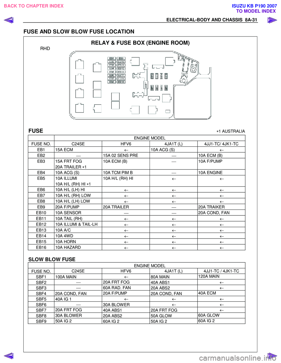
FUSE AND SLOW BLOW FUSE LOCATION
RELAY & FUSE BOX (ENGINE ROOM)
RHD
FUSE ∗1 AUSTRALIA
ENGINE MODEL
FUSE NO. C24SE
HFV6 4JA1T (L) 4JJ1-TC/ 4JK1-TC
EB1 15A ECM
← 10A ACG (S)
←
EB2
15A 02 SENS PRE
10A ECM (B)
EB3 15A FRT FOG 10A ECM (B)
10A F/PUMP
20A TRAILER ∗1
EB4 10A ACG (S)
10A TCM PIM B
10A ENGINE
EB5 10A ILLUMI
10A H/L (RH) HI
← ←
10A H/L (RH) HI ∗1
EB6 10A H/L (LH) HI
← ← ←
EB7 10A H/L (RH) LOW
← ← ←
EB8 10A H/L (LH) LOW
← ← ←
EB9 20A F/PUMP 20A TRAILER
20A TRAIKER
EB10 10A SENSOR 20A COND, FAN
EB11 10A TAIL (RH)
← ← ←
EB12 10A ILLUMI & TAIL-LH
← ← ←
EB13 10A A/C
← ← ←
EB14 10A 4W D
← ← ←
EB15 10A HORN
← ← ←
EB16 10A HAZARD
← ← ←
SLOW BLOW FUSE
ENGINE MODEL
FUSE NO. C24SE
HFV6 4JA1T (L) 4JJ1-TC / 4JK1-TC
SBF1 100A MAIN ←
80A MAIN 120A MAIN
SBF2
20A FRT FOG
40A ABS1 ←
SBF3
60A RAD. FAN
20A ABS2 ←
SBF4 20A COND, FAN 20A F/PUMP
20A COND, FAN 40A ECM
SBF5 40A IG 1
←
← ←
SBF6
30A BLOW ER ←
←
SBF7 20A FRT FOG
40A ABS1 20A FRT FOG ←
SBF8 30A BLOW ER
20A ABS2 50A GLOW 60A GLOW
SBF9
50A IG 2
60A IG 2 50A IG 2 60A IG 2
BACK TO CHAPTER INDEX TO MODEL INDEXISUZU KB P190 2007
Page 4970 of 6020

8A-32 ELECTRICAL-BODY AND CHASSIS
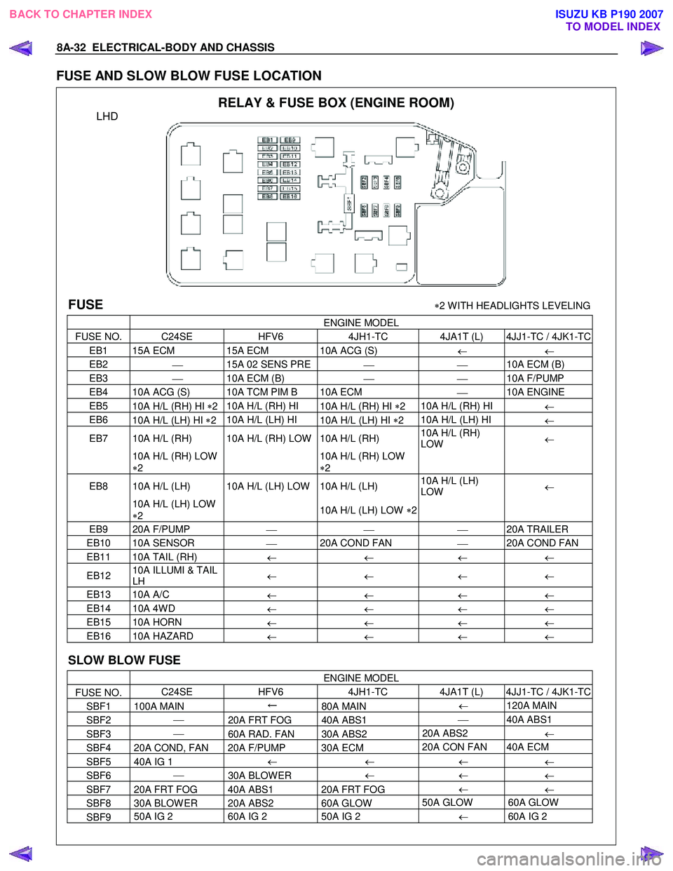
FUSE AND SLOW BLOW FUSE LOCATION
RELAY & FUSE BOX (ENGINE ROOM)
LHD
FUSE ∗2 W ITH HEADLIGHTS LEVELING
ENGINE MODEL
FUSE NO. C24SE HFV6 4JH1-TC 4JA1T (L) 4JJ1-TC / 4JK1-TC
EB1 15A ECM 15A ECM 10A ACG (S)
← ←
EB2
15A 02 SENS PRE
10A ECM (B)
EB3
10A ECM (B)
10A F/PUMP
EB4 10A ACG (S) 10A TCM PIM B 10A ECM
10A ENGINE
EB5
10A H/L (RH) HI ∗2 10A H/L (RH) HI
10A H/L (RH) HI ∗2 10A H/L (RH) HI
←
EB6
10A H/L (LH) HI ∗2 10A H/L (LH) HI
10A H/L (LH) HI ∗2 10A H/L (LH) HI
←
EB7 10A H/L (RH) 10A H/L (RH) LOW 10A H/L (RH) 10A H/L (RH)
LOW ←
10A H/L (RH) LOW
∗ 2
10A H/L (RH) LOW
∗ 2
EB8 10A H/L (LH) 10A H/L (LH) LOW 10A H/L (LH)
10A H/L (LH)
LOW ←
10A H/L (LH) LOW
∗ 2
10A H/L (LH) LOW ∗2
EB9 20A F/PUMP
20A TRAILER
EB10 10A SENSOR
20A COND FAN
20A COND FAN
EB11 10A TAIL (RH)
← ← ← ←
EB12 10A ILLUMI & TAIL
LH ←
← ← ←
EB13 10A A/C
← ← ← ←
EB14 10A 4W D
← ← ← ←
EB15 10A HORN
← ← ← ←
EB16 10A HAZARD
← ← ← ←
SLOW BLOW FUSE
ENGINE MODEL
FUSE NO. C24SE
HFV6 4JH1-TC 4JA1T (L) 4JJ1-TC / 4JK1-TC
SBF1 100A MAIN ←
80A MAIN ←
120A MAIN
SBF2
20A FRT FOG 40A ABS1
40A ABS1
SBF3
60A RAD. FAN 30A ABS2 20A ABS2
←
SBF4 20A COND, FAN 20A F/PUMP 30A ECM 20A CON FAN 40A ECM
SBF5 40A IG 1
←
← ←
←
SBF6
30A BLOW ER ←
←
←
SBF7 20A FRT FOG 40A ABS1 20A FRT FOG ←
←
SBF8 30A BLOW ER 20A ABS2 60A GLOW 50A GLOW 60A GLOW
SBF9 50A IG 2
60A IG 2 50A IG 2
← 60A IG 2
BACK TO CHAPTER INDEX
TO MODEL INDEXISUZU KB P190 2007
Page 5111 of 6020

ELECTRICAL-BODY AND CHASSIS 8A-173
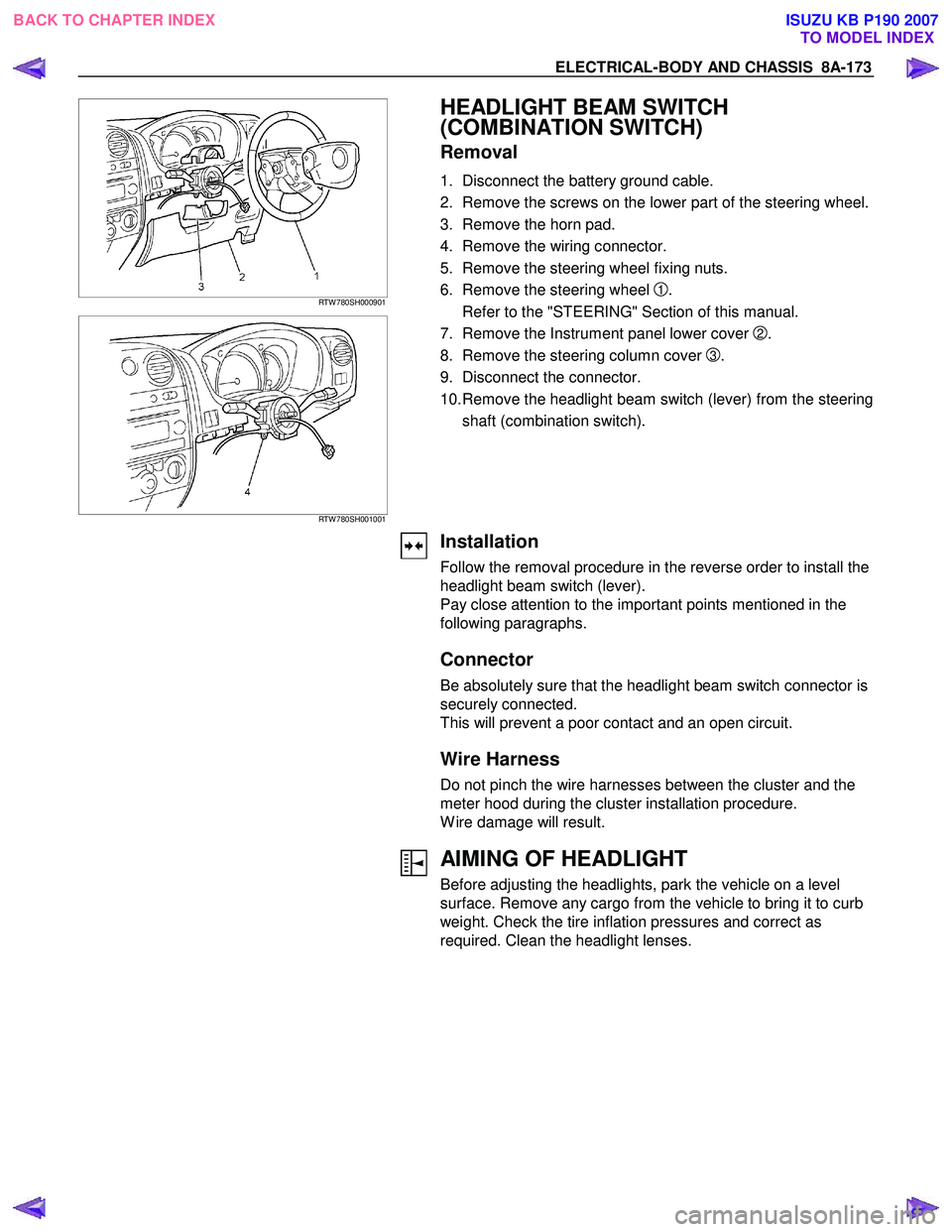
RTW 780SH000901
RTW 780SH001001
HEADLIGHT BEAM SWITCH
(COMBINATION SWITCH)
Removal
1. Disconnect the battery ground cable.
2. Remove the screws on the lower part of the steering wheel.
3. Remove the horn pad.
4. Remove the wiring connector.
5. Remove the steering wheel fixing nuts.
6. Remove the steering wheel
1.
Refer to the "STEERING" Section of this manual.
7. Remove the Instrument panel lower cover
2.
8. Remove the steering column cover
3.
9. Disconnect the connector.
10. Remove the headlight beam switch (lever) from the steering shaft (combination switch).
Installation
Follow the removal procedure in the reverse order to install the
headlight beam switch (lever).
Pay close attention to the important points mentioned in the
following paragraphs.
Connector
Be absolutely sure that the headlight beam switch connector is
securely connected.
This will prevent a poor contact and an open circuit.
Wire Harness
Do not pinch the wire harnesses between the cluster and the
meter hood during the cluster installation procedure.
W ire damage will result.
AIMING OF HEADLIGHT
Before adjusting the headlights, park the vehicle on a level
surface. Remove any cargo from the vehicle to bring it to curb
weight. Check the tire inflation pressures and correct as
required. Clean the headlight lenses.
BACK TO CHAPTER INDEX TO MODEL INDEXISUZU KB P190 2007
Page 5151 of 6020
ELECTRICAL-BODY AND CHASSIS 8A-213
HAZARD WARNING FLASHER, TURN SIGNAL LIGHT, BACKUP LIGHT, HORN AND STOPLIGHT
PARTS LOCATION (RHD)
RTW 78AXF037701 & RTW 78AXF043901
BACK TO CHAPTER INDEX
TO MODEL INDEXISUZU KB P190 2007
Page 5171 of 6020
ELECTRICAL-BODY AND CHASSIS 8A-233
HORN
1. Both sides of horn do not sound
Checkpoint Trouble Cause Countermeasure
Repair the grounding point
Poor ground contact
NG
Horn relay
Grounding point
Reinstall or replace fuse No.
EB15 (10A)
Fuse No EB15 (10A, Relay
and fuse box)
Poor fuse contact or blown
fuse
NG
OK
OK
Reinstall or replace the horn
relay
Poor relay contact or faulty
horn relay
NG
Voltage between connector
3
X3 - ground or 1 X3
- ground (Should be battery
v oltage present) OK
Repair open circuit or
reconnect the connector
Open circuit or poor connector
contact between fuse No.
EB15 (10A) and horn relay
NG
Remov e steering pad and
steering wheel
OK
Horn switch continuity
OK
Repair or replace the horn
switch
Poor switch point contact or
faulty switch
NG
Continuity between
5
X3 - 10 B60
2
X3 - 1 C20 (1 C21 )
OK
Repair open circuit or
connector contact
Open circuit or poor connector
contact
NG
BACK TO CHAPTER INDEX
TO MODEL INDEXISUZU KB P190 2007
Page 5172 of 6020
8A-234 ELECTRICAL-BODY AND CHASSIS
2. One side of horn does not blow
Checkpoint Trouble Cause Countermeasure
Repair open circuit or
reconnect the connector
Open circuit or poor connector
contact
NG Voltage between 1
C20
(1
C21 ) - ground with
horn switch depressed
(Should be battery voltage
present)
Replace the horn assembly
Horn continuity between
connectors
Faulty horn assembly
NG
OK
3. Insufficient horn volume
Clfean and/or remove the
foreign materialStain foreign material in the
horn
NGHorn
Recharge or replace the
batteryBattery conditionDischarged battery
NG
OK
BACK TO CHAPTER INDEX
TO MODEL INDEXISUZU KB P190 2007
Page 5179 of 6020

ELECTRICAL-BODY AND CHASSIS 8A-241
Installation
To install, follow the removal procedure in the reverse order.
Connector
Be absolutely sure that the hazard warning flasher switch
connector is securely connected.
This will prevent a poor contact and an open circuit.
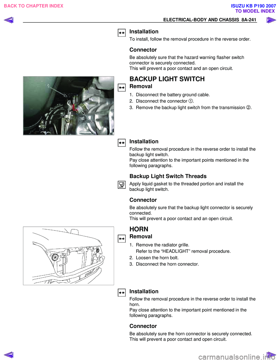
BACKUP LIGHT SWITCH
Removal
1. Disconnect the battery ground cable.
2. Disconnect the connector
1.
3. Remove the backup light switch from the transmission
2.
Installation
Follow the removal procedure in the reverse order to install the
backup light switch.
Pay close attention to the important points mentioned in the
following paragraphs.
Backup Light Switch Threads
Apply liquid gasket to the threaded portion and install the
backup light switch.
Connector
Be absolutely sure that the backup light connector is securely
connected.
This will prevent a poor contact and an open circuit.
HORN
Removal
1. Remove the radiator grille.
Refer to the “HEADLIGHT” removal procedure.
2. Loosen the horn bolt.
3. Disconnect the horn connector.
Installation
Follow the removal procedure in the reverse order to install the
horn.
Pay close attention to the important point mentioned in the
following paragraphs.
Connector
Be absolutely sure the horn connector is securely connected.
This will prevent a poor contact and open circuit.
BACK TO CHAPTER INDEX TO MODEL INDEXISUZU KB P190 2007
Page 5180 of 6020
8A-242 ELECTRICAL-BODY AND CHASSIS
HORN SWITCH
Removal
1. Disable the SRS (Refer to “Disabling the SRS” in Section
9A).
2. Insertion hole for pin push bar at below the steering wheel indicated arrow.
RTW 78ASH001901
3. Check the position of the pins in the holes before insert the
pin push bar. Push the pin in the direction of the arrow.
4. Push the four pins using the φ5 ∼6 bar for cancel the lock on
the four pins.
RTW 78ASH002201
5. Disconnect the SRS air bag connector 1 and horn lead
connector
2 and remove the air bag assembly.
6. Remove the horn switch.
RTW 78ASH002401
Installation
1. Connect the SRS bag connector and horn lead connector.
2. Align each snap stud of the driver air bag to the hole in the steering wheel.
BACK TO CHAPTER INDEX TO MODEL INDEXISUZU KB P190 2007