Page 2144 of 6020
IGNITION SYSTEM 6D2-1
SECTION 6D2
IGNITION SYSTEM
TABLE OF CONTENTS
PAGE
General Description ....................................................................................................... 6D2- 2
Service Precaution ......................................................................................................... 6D2 - 2
Diagnosis ...................................................................................................................... .. 6D2- 2
Ignition Coil.................................................................................................................. ... 6D2- 2
Removal ...................................................................................................................... 6 D2- 2
Installation .................................................................................................................. 6D2- 2
Spark Plug..................................................................................................................... .. 6D2- 3
Removal ...................................................................................................................... 6 D2- 3
Inspection and Repair ............................................................................................... 6D2- 3
Installation .................................................................................................................. 6D2- 4
Crankshaft Angle Sensor............................................................................................... 6D2- 4 Removal ...................................................................................................................... 6 D2- 4
Installation .................................................................................................................. 6D2- 4
Main Data and Specifications ........................................................................................ 6D2- 5
BACK TO CHAPTER INDEX
TO MODEL INDEX
ISUZU KB P190 2007
Page 2145 of 6020
6D2-2 IGNITION SYSTEM
General Description
Ignition is done by the Ignition Module that fires.
Since the cylinder on exhaust stroke requires less energy to
fire its spark plug, energy from the ignition coils can be utilized
to fire the mating cylinder on compression stroke.
A notch in the timing disc on the crankshaft activates the crank
angle sensor which then sends information such as firing order
and starting timing of ignition coil to the ECM.
By receiving signals such as crank position, engine speed,
water temperature and Manifold Absolute Pressure (MAP), the
ECM controls the ignition timing.
Service Precaution
CAUTION:
Always use the correct fastener in the proper location.
When you replace a fastener, use ONLY the exact part
number for that application. ISUZU will call out those
fasteners that require a replacement after removal. ISUZU
will also call out the fasteners that require thread lockers
or thread sealant. UNLESS OTHERWISE SPECIFIED, do
not use supplemental coatings (Paints, greases, or other
corrosion inhibitors) on threaded fasteners or fastener
joint interfaces. Generally, such coatings adversely affect
the fastener torque and the joint clamping force, and may
damage the fastener. When you install fasteners, use the
correct tightening sequence and specifications. Following
these instructions can help you avoid damage to parts
and systems.
Diagnosis
Refer to Section Drivability and Emissions for the diagnosis to
electronic ignition system (El system).
Ignition Coil
Removal
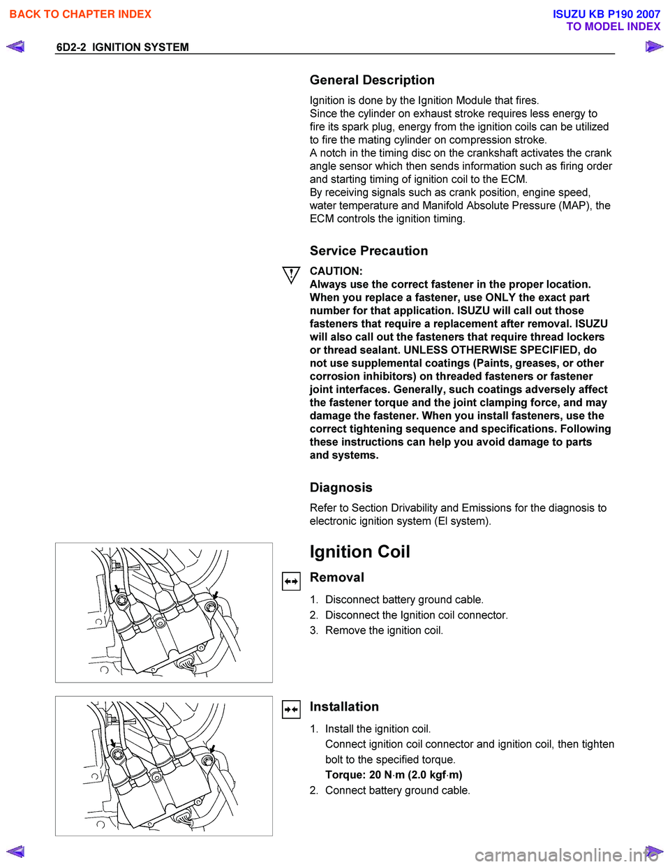
1. Disconnect battery ground cable.
2. Disconnect the Ignition coil connector.
3. Remove the ignition coil.
Installation
1. Install the ignition coil.
Connect ignition coil connector and ignition coil, then tighten bolt to the specified torque.
Torque: 20 N ⋅m (2.0 kgf ⋅m)
2. Connect battery ground cable.
BACK TO CHAPTER INDEX
TO MODEL INDEX
ISUZU KB P190 2007
Page 2146 of 6020
IGNITION SYSTEM 6D2-3
Spark Plug
Removal
1. Remove spark plugs.
Inspection and Repair
The spark plug affects entire engine performance and
therefore its inspection is very important.
• Check electrode and insulator for presence of cracks, and
replace if any.
• Check electrode for wear, and replace if necessary.
• Check gasket for damage, and replace if necessary.
• Measure insulation resistance with an ohmmeter, and
replace if faulty.
• Adjust spark plug gap to 1.0 - 1.1 mm (0.027 in) - 0.8 mm
(0.031 in).
• Check fuel and electrical systems if spark plug is extremely
dirty.
• Use spark plugs having low heat value (hot type plug) if fuel
and electrical systems are normal.
• Use spark plugs having high heat value (cold type plug) i
f
insulator and electrode are extremely burned.
Sooty Spark Plugs
Much deposit of carbon or oil on the electrode and insulator of
spark plug reduces the engine performance.
Possible causes:
• Too rich mixture
• Presence of oil in combustion chamber
• Incorrectly adjusted spark plug gap
Burning Electrodes
This fault is characterized by scorched or heavily oxidized
electrode or blistered insulator nose.
Possible causes:
• Too lean mixture
• Improper heat value
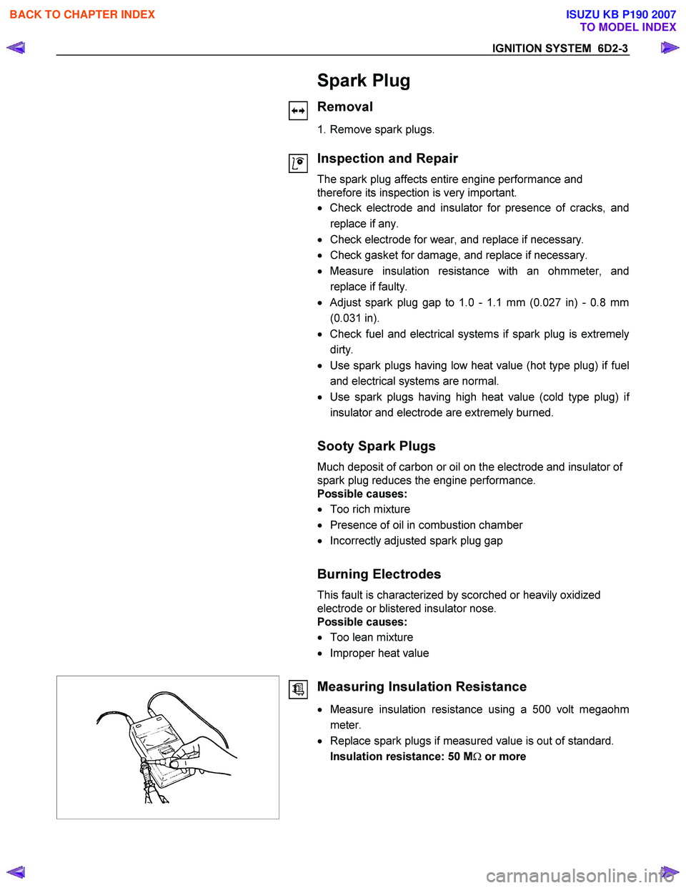
Measuring Insulation Resistance
• Measure insulation resistance using a 500 volt megaohm
meter.
• Replace spark plugs if measured value is out of standard.
Insulation resistance: 50 M Ω or more
BACK TO CHAPTER INDEX
TO MODEL INDEX
ISUZU KB P190 2007
Page 2147 of 6020
6D2-4 IGNITION SYSTEM
Cleaning Spark Plugs
• Clean spark plugs with a spark plug cleaner.
• Raise the ground electrode to an angle of 45 to 60 degrees.
if electrode is wet, dry it gefore cleaning.
•
After spark plug is thoroughly cleaned, check insulator for
presence of cracks.
• Clean threads and metal body with a wire brush.
• File the electrode tip if electrode is extremely worn.
• Bend the ground electrode to adjust the spark plug gap.
Installation
1. Spark plugs
• Tighten spark plugs to the specified torque.
Torque: 20 N ⋅m (2.0 kgf ⋅m)
Crankshaft Angle Sensor
Removal
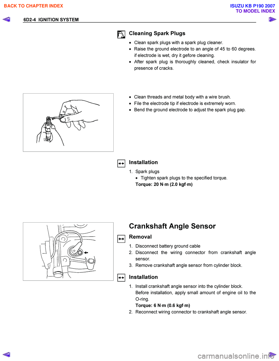
1. Disconnect battery ground cable
2. Disconnect the wiring connector from crankshaft angle sensor.
3. Remove crankshaft angle sensor from cylinder block.
Installation
1. Install crankshaft angle sensor into the cylinder block.
Before installation, apply small amount of engine oil to the O-ring.
Torque: 6 N ⋅m (0.6 kgf ⋅m)
2. Reconnect wiring connector to crankshaft angle sensor.
BACK TO CHAPTER INDEX
TO MODEL INDEX
ISUZU KB P190 2007
Page 2148 of 6020
IGNITION SYSTEM 6D2-5
Main Data and Specifications General Specifications
Ignition System
Ignition Form Electronic Ignition System (El system) with Crankshaft angle Sensor
Spark Plug
Type
No. of Coils and Type Coil Location Torque Electronic Spark Control
2 Solid State
Engine-mounted
20 N ⋅m (2.0 kgf ⋅m)
BACK TO CHAPTER INDEX
TO MODEL INDEX
ISUZU KB P190 2007
Page 2153 of 6020
STARTING AND CHARGING SYSTEM 6D3-5
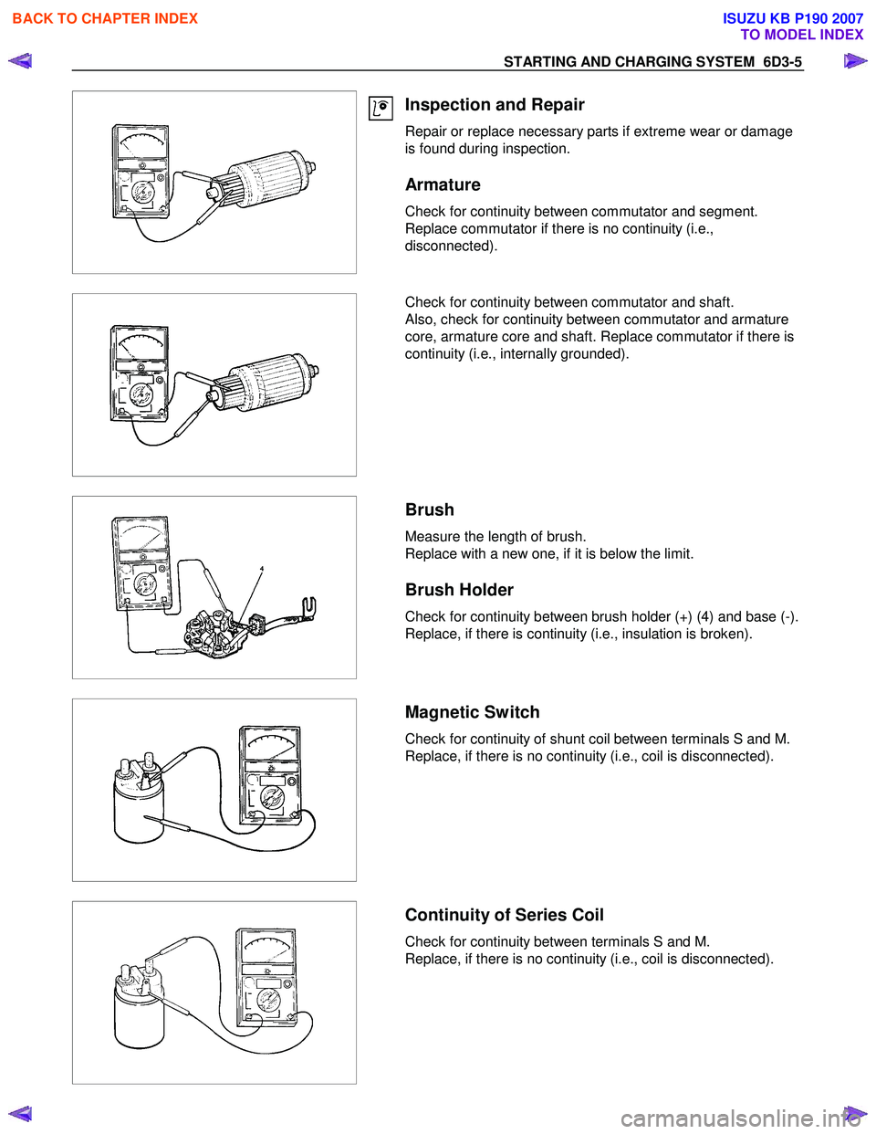
Inspection and Repair
Repair or replace necessary parts if extreme wear or damage
is found during inspection.
Armature
Check for continuity between commutator and segment.
Replace commutator if there is no continuity (i.e.,
disconnected).
Check for continuity between commutator and shaft.
Also, check for continuity between commutator and armature
core, armature core and shaft. Replace commutator if there is
continuity (i.e., internally grounded).
Brush
Measure the length of brush.
Replace with a new one, if it is below the limit.
Brush Holder
Check for continuity between brush holder (+) (4) and base (-).
Replace, if there is continuity (i.e., insulation is broken).
Magnetic Switch
Check for continuity of shunt coil between terminals S and M.
Replace, if there is no continuity (i.e., coil is disconnected).
Continuity of Series Coil
Check for continuity between terminals S and M.
Replace, if there is no continuity (i.e., coil is disconnected).
BACK TO CHAPTER INDEX
TO MODEL INDEX
ISUZU KB P190 2007
Page 2155 of 6020
STARTING AND CHARGING SYSTEM 6D3-7
Charging System
General Description
The charging system is an IC integral regulator charging
system and its main components are connected as shown in
illustration.
The regulator is a solid state type and it is mounted along with
the brush holder assembly inside the generator installed on the
rear end cover.
The generator does not require particular maintenance such as
voltage adjustment. The rectifier connected to the stator coil
has eight diodes to transform AC voltage into DC voltage.
This DC voltage is connected to the output terminal of
generator.
Legend
1 Startor assembly
2 Housing
3 Slipring
4 Screws (2)
5 Regulator
6.Bolt (4) 7 Rectifier assembly
8 Retaining assembly
9 B+ terminal nut and washer
10 Pulley
11 Rotor assembly
12 Ball bearing
2
11
12
2 8
5
4
3 1
11
7
6
10
9
BACK TO CHAPTER INDEX
TO MODEL INDEX
ISUZU KB P190 2007
Page 2162 of 6020
6D3-14 STARTING AND CHARGING SYSTEM
7. To remove the pulley, mount an 8mm Allen key in the vice
with the short end upwards, place a 24mm ring spanner on
the puley nut, position the internal hexagon of the roto
r
shaft onto the Allen ken, loosen the nut and remove the
pulley.
Note: the pulley has an integral boss which locks up against
the bearing,
therefore no thrust collar is provided.
8. Removing the rotor assembly. Remove the four retaining screws from the drive end housing, withdraw the roto
r
complete with the bearing.
Note: the rotor must not be pressed from the drive end housing
using a press as the bearing retaining plate and drive end
housing will be damaged or distorted. Parts removed in this
way must be replaced if the integrity of the generator is to be
maintained.
9. Remove the drive end bearing from the rotor shaft using a
chuck type puler, take care not to distort the fan assembl
y
during this process.
10. Remove the slipring end bearing using the same meghod as in 9.
Clean
Thoroughly clean all components except the rotor and stator
with an approved cleaning agent. Ensure that all traced of oil
and dirt are removed. If an abrasive cleaner is used to remove
scale and paint from the housings take care not to abrade the
bearing and mounting spigot surfaces. The rotor and stator
must be cleaned with compressed air only, the use of solvents
could cause damage to the insulating materials.
Inspection
1. Rectifier assembly
The following test equipment is required.
The recitifier assembly is not repairable and must be replaced
if a faulty diode is detected during inspection.
(a)
Adiode tester where the DC output at the test probes does
not exceed 14 volts or in the case of AC testers 12 volts
RMS. This is to ensue that when inspection rectifiers fitted
with zener power diodes the forward and reverse checks
are completer and are not masked by the diode turning on
due to the zener breakdown voltage.
(b) A zenere diode tester with a DC output in excess of 30 volts, the tester should also incorporate internal current
limiting set to 5 Ma. to prevent high currents during
inspection.
(c) Diodes can be destroyed during service due to high temperature and overload, open circuits are usually a result
of excessive voltage.
BACK TO CHAPTER INDEX
TO MODEL INDEX
ISUZU KB P190 2007