2007 ISUZU KB P190 oil
[x] Cancel search: oilPage 2097 of 6020
ENGINE MECHANICAL (C24SE) 6A-83
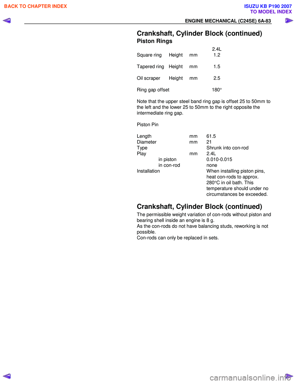
Crankshaft, Cylinder Block (continued)
Piston Rings
2.4L
Square ring Height mm 1.2
Tapered ring Height mm 1.5
Oil scraper Height mm 2.5
Ring gap offset 180 °
Note that the upper steel band ring gap is offset 25 to 50mm to
the left and the lower 25 to 50mm to the right opposite the
intermediate ring gap.
Piston Pin
Length mm 61.5
Diameter mm 21
Type Shrunk into con-rod
Play mm 2.4L
in piston 0.010-0.015
in con-rod none
Installation W hen installing piston pins,
heat con-rods to approx.
280 °C in oil bath. This
temperature should under no
circumstances be exceeded.
Crankshaft, Cylinder Block (continued)
The permissible weight variation of con-rods without piston and
bearing shell inside an engine is 8 g.
As the con-rods do not have balancing studs, reworking is not
possible.
Con-rods can only be replaced in sets.
BACK TO CHAPTER INDEX
TO MODEL INDEX
ISUZU KB P190 2007
Page 2102 of 6020
6A-88 ENGINE MECHANICAL (C24SE)
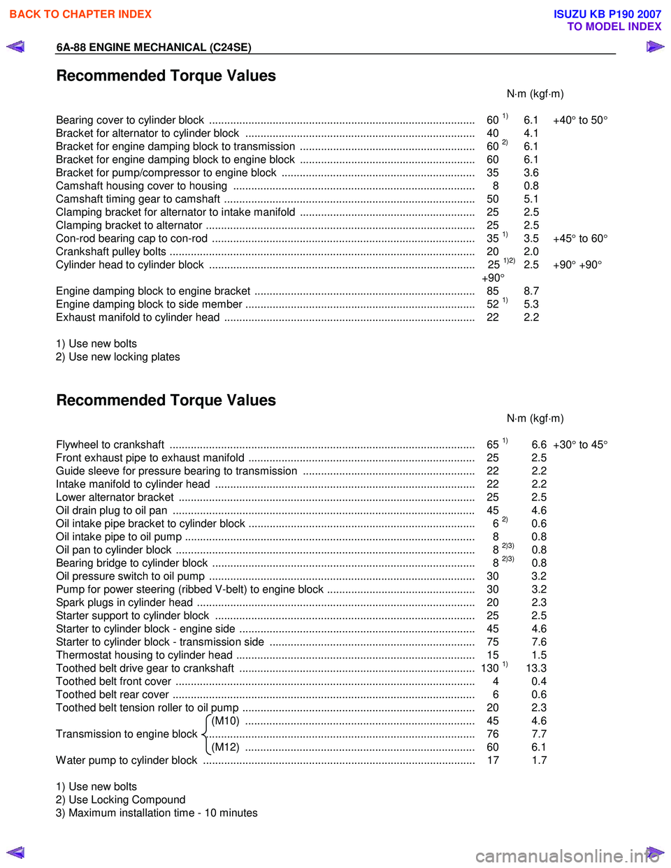
Recommended Torque Values
N⋅m (kgf ⋅m)
Bearing cover to cylinder block ........................................................................................ 60
1) 6.1 +40 ° to 50 °
Bracket for alternator to cylinder block ............................................................................ 40 4.1
Bracket for engine damping block to transmission .......................................................... 60
2) 6.1
Bracket for engine damping block to engine block .......................................................... 60 6.1
Bracket for pump/compressor to engine block ................................................................ 35 3.6
Camshaft housing cover to housing ................................................................................ 8 0.8
Camshaft timing gear to camshaft ................................................................................... 50 5.1
Clamping bracket for alternator to intake manifold .......................................................... 25 2.5
Clamping bracket to alternator ......................................................................................... 25 2.5
Con-rod bearing cap to con-rod ....................................................................................... 35
1) 3.5 +45 ° to 60 °
Crankshaft pulley bolts ..................................................................................................... 2 0 2.0
Cylinder head to cylinder block ........................................................................................ 25
1)2) 2.5 +90 ° +90 °
+90 °
Engine damping block to engine bracket ......................................................................... 85 8.7
Engine damping block to side member ............................................................................ 52
1) 5.3
Exhaust manifold to cylinder head ................................................................................... 22 2.2
1) Use new bolts
2) Use new locking plates
Recommended Torque Values
N⋅m (kgf ⋅m)
Flywheel to crankshaft ..................................................................................................... 65
1) 6.6 +30° to 45 °
Front exhaust pipe to exhaust manifold ........................................................................... 25 2.5
Guide sleeve for pressure bearing to transmission ......................................................... 22 2.2
Intake manifold to cylinder head ...................................................................................... 22 2.2
Lower alternator bracket .................................................................................................. 25 2.5
Oil drain plug to oil pan .................................................................................................... 45 4.6
Oil intake pipe bracket to cylinder block ........................................................................... 6
2) 0.6
Oil intake pipe to oil pump ................................................................................................ 8 0.8
Oil pan to cylinder block ................................................................................................... 8
2)3) 0.8
Bearing bridge to cylinder block ....................................................................................... 8 2)3) 0.8
Oil pressure switch to oil pump ........................................................................................ 30 3.2
Pump for power steering (ribbed V-belt) to engine block ................................................. 30 3.2
Spark plugs in cylinder head ............................................................................................ 20 2. 3
Starter support to cylinder block ...................................................................................... 25 2.5
Starter to cylinder block - engine side .............................................................................. 45 4.6
Starter to cylinder block - transmission side .................................................................... 75 7.6
Thermostat housing to cylinder head ............................................................................... 15 1.5
Toothed belt drive gear to crankshaft .............................................................................. 130
1) 13.3
Toothed belt front cover ................................................................................................... 4 0.4
Toothed belt rear cover .................................................................................................... 6 0.6
Toothed belt tension roller to oil pump ............................................................................. 20 2.3 (M10) ............................................................................ 45 4.6
Transmission to engine block ......................................................................................... 76 7.7 (M12) ............................................................................ 60 6.1
W ater pump to cylinder block .......................................................................................... 17 1.7
1) Use new bolts
2) Use Locking Compound
3) Maximum installation time - 10 minutes
BACK TO CHAPTER INDEX
TO MODEL INDEX
ISUZU KB P190 2007
Page 2106 of 6020
6B-2 ENGINE COOLING
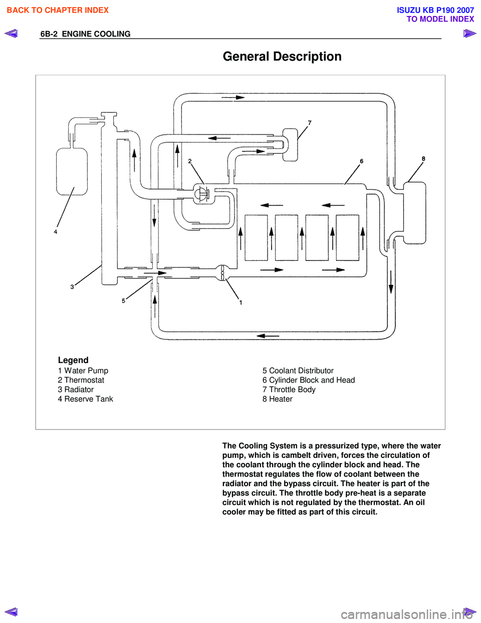
General Description
Legend
1 W ater Pump
2 Thermostat
3 Radiator
4 Reserve Tank 5 Coolant Distributor
6 Cylinder Block and Head
7 Throttle Body
8 Heater
The Cooling System is a pressurized type, where the water
pump, which is cambelt driven, forces the circulation of
the coolant through the cylinder block and head. The
thermostat regulates the flow of coolant between the
radiator and the bypass circuit. The heater is part of the
bypass circuit. The throttle body pre-heat is a separate
circuit which is not regulated by the thermostat. An oil
cooler may be fitted as part of this circuit.
BACK TO CHAPTER INDEX
TO MODEL INDEX
ISUZU KB P190 2007
Page 2109 of 6020
ENGINE COOLING 6B-5
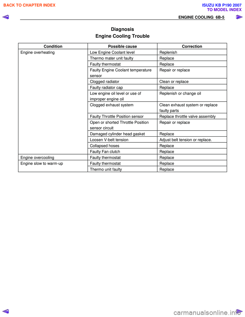
Diagnosis
Engine Cooling Trouble
Condition Possible cause Correction
Engine overheating Low Engine Coolant level Replenish
Thermo mater unit faulty Replace
Faulty thermostat Replace
Faulty Engine Coolant temperature
sensor Repair or replace
Clogged radiator Clean or replace
Faulty radiator cap Replace
Low engine oil level or use of
improper engine oil Replenish or change oil
Clogged exhaust system Clean exhaust system or replace
faulty parts
Faulty Throttle Position sensor Replace throttle valve assembly
Open or shorted Throttle Position
sensor circuit Repair or replace
Damaged cylinder head gasket Replace
Loosen V-belt tension Adjust belt tension or replace.
Collapsed hoses Replace
Faulty Fan clutch Replace
Engine overcooling Faulty thermostat Replace
Engine slow to warm-up Faulty thermostat Replace
Thermo unit faulty Replace
BACK TO CHAPTER INDEX
TO MODEL INDEX
ISUZU KB P190 2007
Page 2110 of 6020
6B-6 ENGINE COOLING
Draining and Refilling Cooling
System
Before draining the cooling system, inspect the system and
perform any necessary service to ensure that it is clean, does
not leak and is in proper working order. The engine coolant
level should be between the "MIN" and "MAX" lines of reserve
tank when the engine is cold. If low, check for leakage and add
engine coolant up to the "MAX" line. There should not be any
excessive deposit of rust or scales around the radiator cap or
radiator filler hole, and the engine coolant should also be free
from oil.
Replace the engine coolant if excessively dirty.
1. Completely drain the cooling system by opening the drain
plug at the bottom of the radiator.
2. Remove the radiator cap.
WARNING: TO AVOID THE DANGER OF BEING BURNED,
DO NOT REMOVE THE CAP WHILE THE ENGINE AND
RADIATOR ARE STILL HOT. SCALDING FLUID AND
STEAM CAN BE BLOWN OUT UNDER PRESSURE.
3. Disconnect all hoses from the engine coolant reserve tank.
Scrub and clean the inside of the reserve tank with soap and water. Flush it well with clean water, then drain it. Install
the reserve tank and hoses.
4. Refill the cooling system with the engine coolant using a solution that is at least 50 percent antifreeze.
5. Fill the radiator to the base of the filler neck.
Fill the engine coolant reserve tank to "MAX" line when the engine is cold.
6. Block the drive wheels and firmly apply the parking brake and place the shift lever in the "NEUTRAL" position.
7. Remove the radiator cap. Start the engine and warm it up at 2,500 - 3,000 rpm for about 30 minutes.
8. W hen the air comes out from the radiator filler neck and the engine coolant level has gone down, replenish with the
engine coolant. Repeat this procedure until the engine
coolant level does not go down. Then stop the engine and
install the radiator cap. Let the engine cool down.
9. After the engine has cooled, replenish with engine coolant up to the "MAX" line of the reserve tank.
10. Start the engine. W ith the engine running at 3,000 rpm, make sure there is no running water sound from the heate
r
core (behind the center console).
11. If the running water sound is heard, repeat steps 8 to 10.
BACK TO CHAPTER INDEX
TO MODEL INDEX
ISUZU KB P190 2007
Page 2121 of 6020
ENGINE FUEL (C24SE) 6C-3
W hen working on the fuel system, there are several things to
keep in mind:
•
Any time the fuel system is being worked on, disconnect the
negative battery cable except for those tests where batter
y
voltage is required.
•
Always keep a dry chemical (Class B) fire extinguisher near
the work area.
• Replace all pipes with the same pipe and fittings that were
removed.
• Clean and inspect "O" rings. Replace if required.
•
Always relieve the line pressure before servicing any fuel
system components.
• Do not attempt repairs on the fuel system until you have
read the instructions and checked the pictures relating to
that repair.
• Adhere to all Notices and Cautions.
All gasoline engines are designed to use only unleaded
gasoline. Unleaded gasoline must be used for proper emission
control system operation.
Its use will also minimize spark plug fouling and extend engine
oil life. Using leaded gasoline can damage the emission control
system and could result in loss of emission warranty coverage.
All cars are equipped with an Evaporative Emission Control
System. The purpose of the system is to minimize the escape
of fuel vapors to the atmosphere.
Service Precaution
CAUTION:
Always use the correct fastener in the proper location.
When you replace a fastener, use ONLY the exact part
number for that application. ISUZU will call out those
fasteners that require a replacement after removal. ISUZU
will also call out the fasteners that require thread lockers
or thread sealant. UNLESS OTHERWISE SPECIFIED, do
not use supplemental coatings (Paints, greases, or othe
r
corrosion inhibitors) on threaded fasteners or fastene
r
joint interfaces. Generally, such coatings adversely affect
the fastener torque and the joint clamping force, and may
damage the fastener. When you install fasteners, use the
correct tightening sequence and specifications. Following
these instructions can help you avoid damage to parts
and systems.
BACK TO CHAPTER INDEX
TO MODEL INDEX
ISUZU KB P190 2007
Page 2128 of 6020

6C-10 ENGINE FUEL (C24SE)
Fuel Tube / Quick – Connector Fittings
Precautions
• Do not light a match or create a flame.
• Keep flames away from your work area to prevent
flammable materials from catching fire.
• Disconnect battery ground cable to prevent
electrical shorts.
• Pre-treat piping system or associated parts from
thermal damage or from spattering when welding
or similar heat-generating work.
Cautions During Work
140R100032
Legend
(1) O-ring
(2) Port
(3) Connector
(4) Plastic Tube
Do not expose the assembly to battery electrolyte or do
not wipe the assembly with a cloth used to wipe off spilt
battery electorolyte.
Piping that has been splattered with battery electrolyte
or battery electrolyte soaked cloth that was wiped on the
piping cannot be used.
Removal
1. Open the fuel cap to relieve the fuel pressure in the
tank.
Use compressed air to remove any dirt on the fuel
quick connect fittings prior to disconnecting the
fittings.
141R100002
W hen disconnecting the fuel pipe, cover the area
with a cloth to prevent fuel from splashing as the
fuel pipe may still have some pressure in it.
2. For removal of the quick connector, hold the quick
connector in one hand, and pull out the connento
r
with the other hand while pressing the square
relieve button of the connector, as illustrated.
140R100037
NOTE: Do not use tools of any kind. Only use bare
hands when disconnecting the connector. Use a
lubricant (light oil) and/or push and pull the connecto
r
until the pipe is disconnected.
Cover the connectors that was removed with a
plastic bag, to prevent dust or rain water from
entering.
BACK TO CHAPTER INDEX
TO MODEL INDEX
ISUZU KB P190 2007
Page 2129 of 6020
ENGINE FUEL (C24SE) 6C-11
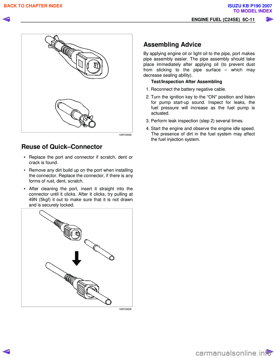
140R100028
Reuse of Quick–Connector
• Replace the port and connector if scratch, dent or
crack is found.
• Remove any dirt build up on the port when installing the connector. Replace the connector, if there is an
y
forms of rust, dent, scratch.
•
After cleaning the port, insert it straight into the
connector until it clicks. After it clicks, try pulling at
49N (5kgf) it out to make sure that it is not drawn
and is securely locked.
140R100036
Assembling Advice
By applying engine oil or light oil to the pipe, port makes
pipe assembly easier. The pipe assembly should take
place immediately after applying oil (to prevent dust
from sticking to the pipe surface – which ma
y
decrease sealing ability).
Test/Inspection After Assembling
1. Reconnect the battery negative cable.
2. Turn the ignition key to the “ON" position and listen
for pump start-up sound. Inspect for leaks, the
fuel pressure will increase as the fuel pump is
actuated.
3. Perform leak inspection (step 2) several times.
4. Start the engine and observe the engine idle speed.
The presence of dirt in the fuel system may affect
the fuel injection system.
BACK TO CHAPTER INDEX
TO MODEL INDEX
ISUZU KB P190 2007