2007 ISUZU KB P190 lock
[x] Cancel search: lockPage 2778 of 6020
Engine Mechanical – V6 Page 6A1–1
Page 6A1–1
Section 6A1
Engine Mechanical – V6
ATTENTION
Before performing any service operation or other procedure described in this Section, refer to 1.1 WARNING,
CAUTION and NOTES for correct workshop practices with regard to safety and/or property damage.
1 General Information ............................................................................................................ ...................8
MY06 Update .................................................................................................................... ......................................8
1.1 WARNING, CAUTION and NOTES .................................................................................................... ...................8
Definition of WARNING, CAUT ION and NOTE Statements ............................................................................. ....8
WARNING defined ................................................................................................................ .............................8
CAUTION defined ................................................................................................................ ..............................8
NOTE defined................................................................................................................... ..................................9
1.2 Engine Components .............................................................................................................. ..............................10
Major Component Assemblies............................................................................................................................ 10
Intake Manifold Assembly ....................................................................................................... ............................11
Engine Front Cover............................................................................................................. .................................12
Camshaft Timing Components ..................................................................................................... ......................13
Camshaft Cove r Assembly........................................................................................................ ..........................14
Cylinder Head Assembly ......................................................................................................... ............................15
Oil Pump ....................................................................................................................... ........................................16
Engine Block Assembly .......................................................................................................... ............................17
Pistons, Rings, Bearing and Connecting Rod ..................................................................................... ..............18
Oil Pan Assembly............................................................................................................... ..................................19
Oil Filter Assembly ............................................................................................................ ..................................20
1.3 Engine Serial Number........................................................................................................... ...............................21
1.4 Engine Construction............................................................................................................ ................................22
Cylinder Block ................................................................................................................. .....................................22
Cylinder Heads ..................................................................................................................................................... 22
Crankshaft ..................................................................................................................... .......................................23
Pistons, Pins and Connecting Rods .............................................................................................. ....................23
Camshaft Driv e System ....................................................................................................................................... 24
1.5 Engine Lubrication System .................................................................................................................................25
Lubrication Description........................................................................................................ ...............................25
1.6 Service Notes .................................................................................................................. .....................................26
Cleanliness and Care........................................................................................................... ................................26
Replacing Engine Gaskets .................................................................................................................................. 26
Re-Using Gaskets and Applying Sealants......................................................................................... ...............26
Separating Co mponents................................................................................................................................... 26
Cleaning Gasket Surfaces ................................................................................................................................ 26
Assembling Components ................................................................................................................................. 26
Use of Room Temperature Vulcanising and Anaerobic Sealer....................................................................... .27
Room Temperature Vu lcanising Sealer............................................................................................ ................27
Anaerobic Sealer ............................................................................................................... ...............................27
Pipe Joint Compound ............................................................................................................ ...........................28
Separating Parts ............................................................................................................... ...................................28
Tools and Equipment ............................................................................................................ ..............................28
Fasteners .............................................................................................................................................................. 29
Clamp Load ..................................................................................................................... .................................29
Torque Angle and Torque to Yield Fastener s................................................................................................... 29
2 Diagnosis ...................................................................................................................... ........................30
2.1 Engine Diagnosis ............................................................................................................... ..................................30
2.2 Symptoms ....................................................................................................................... .....................................31
Strategy Based Diagnosis................................................................................................................................... 31
BACK TO CHAPTER INDEX
TO MODEL INDEX
ISUZU KB P190 2007
Page 2783 of 6020
Engine Mechanical – V6 Page 6A1–6
Page 6A1–6
Reassemble ........................................................................................................................................................ 257
Reinstall .............................................................................................................................................................. 257
4.3 Flexplate Assembly ............................................................................................................. ..............................259
Remove ............................................................................................................................................................... 259
Clean................................................................................................................................................................... 259
Inspect ........................................................................................................................ ........................................260
Reinstall .............................................................................................................................................................. 260
4.4 Crankshaft Rear Seal and Plate Assembly ........................................................................................ ..............262
Remove ............................................................................................................................................................... 262
Reinstall .............................................................................................................................................................. 263
4.5 Pistons, Pins, Rings, Connecting Rods and Big-end Bearings ..................................................................... 265
Remove ............................................................................................................................................................... 265
Disassemble ....................................................................................................................................................... 268
Clean and Inspect .............................................................................................................. ................................269
Piston Cleaning Procedure...................................................................................................... .......................269
Piston Inspection Procedure .................................................................................................... ......................269
Piston Measurement ............................................................................................................. .........................270
Piston Ring Measurement ........................................................................................................ ......................271
Connecting Rod Cleaning Procedure .............................................................................................. ...............272
Connecting Rod Visual Inspection Procedure ..................................................................................... ...........272
Connecting Rod Meas urement Procedure ........................................................................................... ..........272
Reasse mble ........................................................................................................................................................ 274
Piston and Piston Pin ..................................................................................................................................... 274
Piston Ring .................................................................................................................... .................................275
Connecting Rod Bearing ................................................................................................................................ 276
Reinstall .............................................................................................................................................................. 277
Piston Connecting Rod and Connecting Rod Bearing Inst allation .................................................................. 277
Connecting Rod Bearing Clearance Measurement Procedure....................................................................... 278
Connecting Rod Final Assembly Procedure ........................................................................................ ...........279
4.6 Crankshaft and Ma in Bearings ................................................................................................... ......................281
Crankshaft End Play Measurement ................................................................................................ ..................281
Remove ............................................................................................................................................................... 281
Crankshaft Bearing............................................................................................................. ............................283
Clean and Inspect .............................................................................................................. ................................283
Crankshaft and Main Bearing Cleaning ........................................................................................... ...............283
Crankshaft and Main Bear ing Visual Inspection .................................................................................. ...........284
Crankshaft Main B earing Inspection............................................................................................. ..................285
Crankshaft M easurement ......................................................................................................... ......................286
Reinstall .............................................................................................................................................................. 288
Crankshaft Bearing Installation Procedure ...................................................................................... ...............288
Crankshaft Main Bearing Clearance Measurement .................................................................................. ......289
Crankshaft Final Instal lation Procedure........................................................................................ ..................291
4.7 Cylinder Block ................................................................................................................. ...................................293
Disassemble ....................................................................................................................................................... 293
Clean................................................................................................................................................................... 297
Inspect ........................................................................................................................ ........................................297
Visual Inspection .............................................................................................................. ..............................297
Measuring Cylinder Bore Diameter ............................................................................................... .................297
Measuring Cylinder Bore Taper.................................................................................................. ....................298
Measuring Cylinder Bo re Out-of-Round ........................................................................................... ..............298
Deck Flatness Inspection ............................................................................................................................... 298
Reassemble ........................................................................................................................................................ 299
4.8 Thread Repairs ................................................................................................................................................... 303
General Information ............................................................................................................ ...............................303
General Thread Repair .......................................................................................................... ............................304
Main Bearing Cap Bolt Hole Thread Repair ....................................................................................... ..............310
Cylinder Head Bolt Hole Thread Repair .......................................................................................... .................315
4.9 Thread Repair Specifications................................................................................................... .........................322
Left-hand Cylinder Head Camshaft Cover Face .................................................................................... ..........322
Left-hand Cylinder H ead Front Face ............................................................................................. ...................323
BACK TO CHAPTER INDEX
TO MODEL INDEX
ISUZU KB P190 2007
Page 2784 of 6020
Engine Mechanical – V6 Page 6A1–7
Page 6A1–7
Left-hand Cylinder Head Intake Face ............................................................................................ ...................324
Left-hand Cylinder H ead Exhaust Face ........................................................................................... ................325
Left-hand Cylinder H ead Rear Face .............................................................................................. ...................326
Right-hand Cylinder Head Camshaft Cover Face ................................................................................... ........327
Right-hand Cylinder Head Front Face............................................................................................ ..................328
Right-hand Cylinder Head Intake Face ........................................................................................... .................329
Right-hand Cylinder He ad Exhaust Face .......................................................................................... ...............330
Right-hand Cylinder Head Rear Face ............................................................................................. ..................331
Engine Block Front ............................................................................................................................................ 332
Engine Block Left-hand Side .................................................................................................... ........................333
Engine Block Ri ght-hand Side ................................................................................................... .......................334
Engine Block Rear .............................................................................................................. ...............................335
Engine Block Bottom......................................................................................................................................... 336
Engine Block Left-hand Deck Face ............................................................................................... ...................337
Engine Block Righ t-hand Deck Face.............................................................................................. ..................338
Engine Front Cover............................................................................................................. ...............................339
Upper Intake Manifold Top ...................................................................................................... ..........................340
Upper Intake Mani fold Front .................................................................................................... .........................341
Upper Intake Ma nifold Rear..................................................................................................... ..........................342
Lower Intake Ma nifold Top...................................................................................................... ..........................343
Oil Pan Front .................................................................................................................. ....................................344
Oil Pan Rear........................................................................................................................................................ 345
Oil Pan Bottom ................................................................................................................................................... 346
5 Specifications .....................................................................................................................................347
6 Torque Wrench Specifications................................................................................................... .......351
7 Special Tools .................................................................................................................. ....................353
BACK TO CHAPTER INDEX
TO MODEL INDEX
ISUZU KB P190 2007
Page 2785 of 6020
Engine Mechanical – V6 Page 6A1–8
Page 6A1–8
1 General Information
The HFV6 engine features a closed vee, deep skirt die cast aluminium cylinder block with cast iron cylinder liners,
internally balanced crankcase, full length wa ter jackets and six bolt main bearing caps.
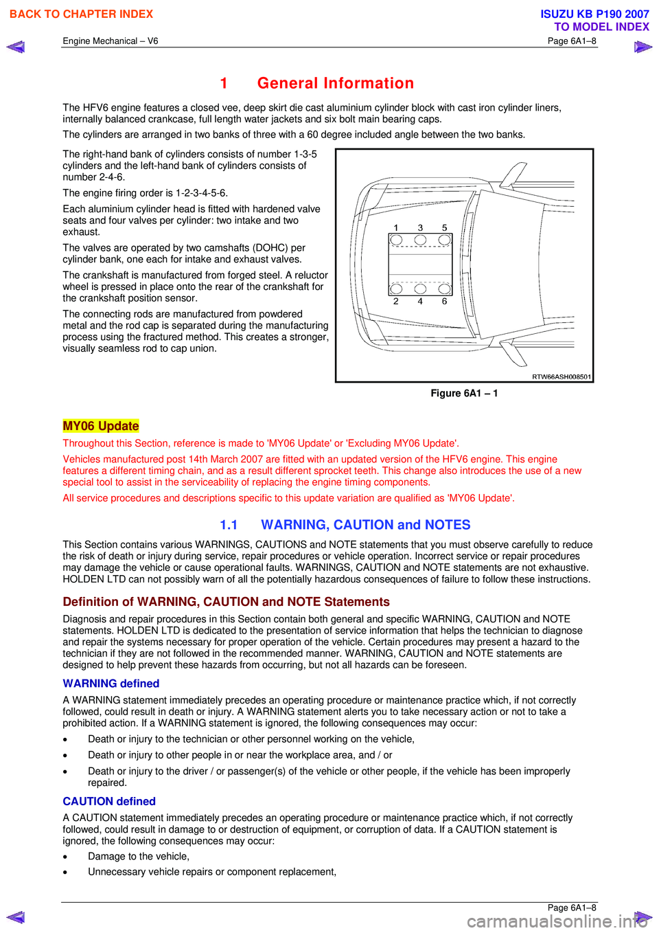
The cylinders are arranged in two banks of three with a 60 degree included angle between the two banks.
The right-hand bank of cylinders consists of number 1-3-5
cylinders and the left-hand bank of cylinders consists of
number 2-4-6.
The engine firing order is 1-2-3-4-5-6.
Each aluminium cylinder head is fitted with hardened valve
seats and four valves per cylinder: two intake and two
exhaust.
The valves are operated by two camshafts (DOHC) per
cylinder bank, one each for intake and exhaust valves.
The crankshaft is manufactured from forged steel. A reluctor
wheel is pressed in place onto the rear of the crankshaft for
the crankshaft position sensor.
The connecting rods are m anufactured from powdered
metal and the rod cap is separ ated during the manufacturing
process using the fractured me thod. This creates a stronger,
visually seamless rod to cap union.
Figure 6A1 – 1
MY06 Update
Throughout this Section, reference is made to 'MY06 Update' or 'Excluding MY06 Update'.
Vehicles manufactured post 14th Marc h 2007 are fitted with an updated version of the HFV6 engine. This engine
features a different timing chain, and as a result different sprocket teeth. This change also introduces the use of a new
special tool to assist in the serviceab ility of replacing the engine timing components.
All service procedures and descriptions specific to this update variation are qualified as 'MY06 Update'.
1.1 WARNING, CAUTION and NOTES
This Section contains various WARNING S, CAUTIONS and NOTE statements that y ou must observe carefully to reduce
the risk of death or injury during servic e, repair procedures or vehicle operation. Incorrect service or repair procedures
may damage the vehicle or cause operat ional faults. WARNINGS, CAUTION and NOTE statements are not exhaustive.
HOLDEN LTD can not possibly warn of a ll the potentially hazardous consequences of failure to follow these instructions.
Definition of WARNING, CAUTION and NOTE Statements
Diagnosis and repair procedures in this Section contain both general and specific WARNING, CAUTION and NOTE
statements. HOLDEN LTD is dedicated to the presentation of service information that helps the technician to diagnose
and repair the systems necessary for proper operation of the vehicle. Certain procedures may present a hazard to the
technician if they are not followed in the reco mmended manner. WARNING, CAUTION and NOTE statements are
designed to help prevent these hazards from o ccurring, but not all hazards can be foreseen.
WARNING defined
A WARNING statement immediately precedes an operating procedure or maint enance practice which, if not correctly
followed, could result in death or injury . A WARNING statement alerts you to ta ke necessary action or not to take a
prohibited action. If a WARNING statement is ignored, the following consequences may occur:
• Death or injury to the technician or other personnel working on the vehicle,
• Death or injury to other people in or near the workplace area, and / or
• Death or injury to the driver / or passenger(s) of the vehicle or other people, if the vehicle has been improperly
repaired.
CAUTION defined
A CAUTION statement immediately prec edes an operating procedure or maintenance practice which, if not correctly
followed, could result in damage to or destruction of equi pment, or corruption of data. If a CAUTION statement is
ignored, the following consequences may occur:
• Damage to the vehicle,
• Unnecessary vehicle repairs or component replacement,
BACK TO CHAPTER INDEX
TO MODEL INDEX
ISUZU KB P190 2007
Page 2794 of 6020
Engine Mechanical – V6 Page 6A1–17
Page 6A1–17
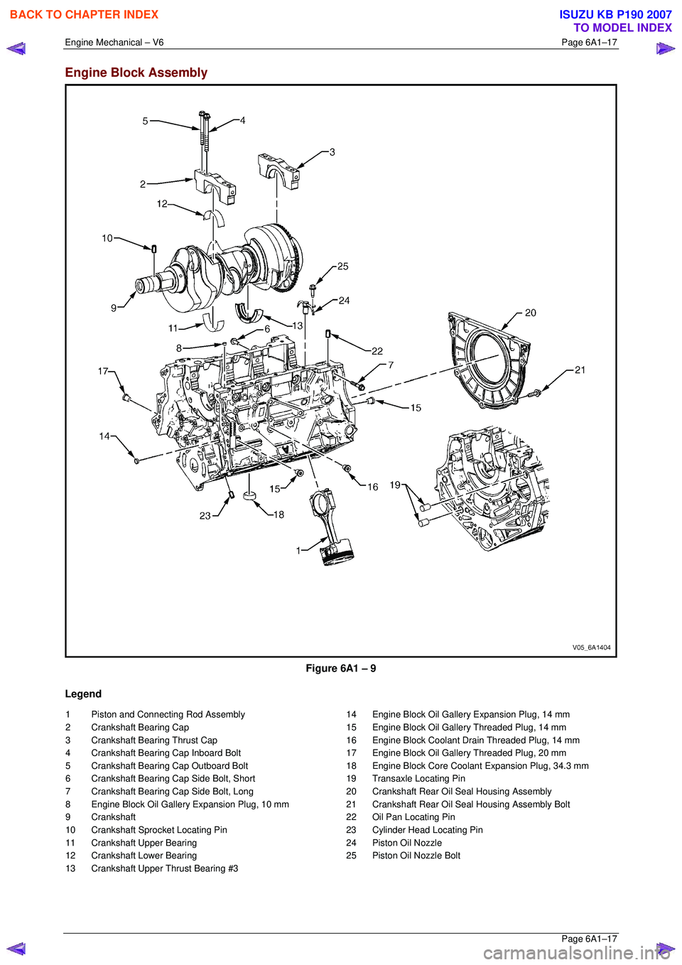
Engine Block Assembly
Figure 6A1 – 9
Legend
1 Piston and Connecting Rod Assembly
2 Crankshaft Bearing Cap
3 Crankshaft Bearing Thrust Cap
4 Crankshaft Bearing Cap Inboard Bolt
5 Crankshaft Bearing Cap Outboard Bolt
6 Crankshaft Bearing Cap Side Bolt, Short
7 Crankshaft Bearing Cap Side Bolt, Long
8 Engine Block Oil Gallery Expansion Plug, 10 mm
9 Crankshaft
10 Crankshaft Sprocket Locating Pin
11 Crankshaft Upper Bearing
12 Crankshaft Lower Bearing
13 Crankshaft Upper Thrust Bearing #3 14 Engine Block Oil Gallery Expansion Plug, 14 mm
15 Engine Block Oil Gallery Threaded Plug, 14 mm
16 Engine Block Coolant Drain Threaded Plug, 14 mm
17 Engine Block Oil Gallery Threaded Plug, 20 mm
18 Engine Block Core Coolant Expansion Plug, 34.3 mm
19 Transaxle Locating Pin
20 Crankshaft Rear Oil Seal Housing Assembly
21 Crankshaft Rear Oil Seal Housing Assembly Bolt
22 Oil Pan Locating Pin
23 Cylinder Head Locating Pin
24 Piston Oil Nozzle
25 Piston Oil Nozzle Bolt
BACK TO CHAPTER INDEX
TO MODEL INDEX
ISUZU KB P190 2007
Page 2798 of 6020
Engine Mechanical – V6 Page 6A1–21
Page 6A1–21
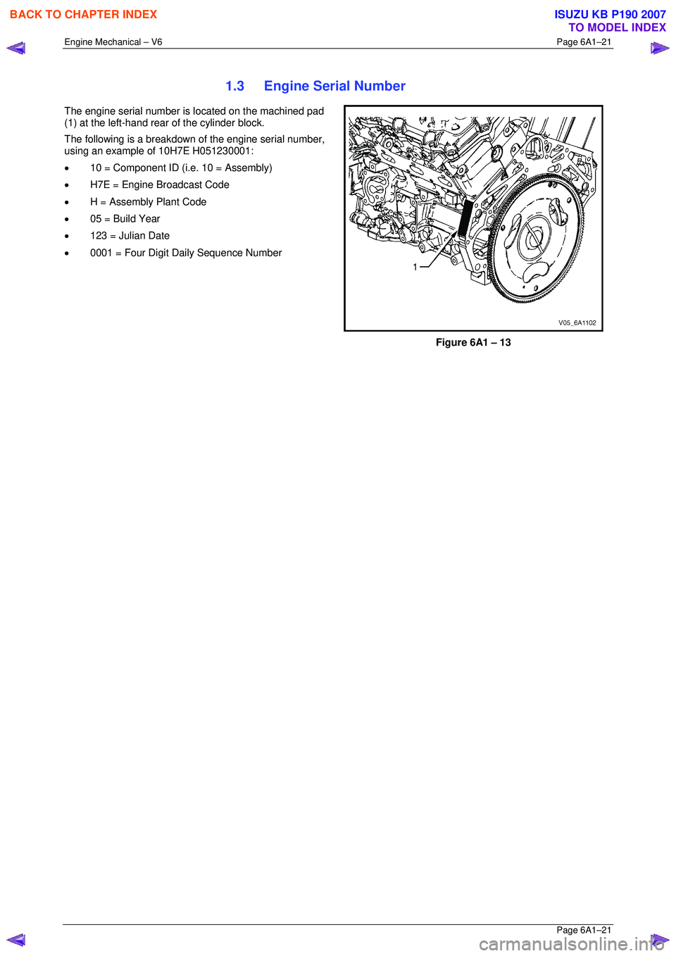
1.3 Engine Serial Number
The engine serial number is located on the machined pad
(1) at the left-hand rear of the cylinder block.
The following is a breakdown of the engine serial number,
using an example of 10H7E H051230001:
• 10 = Component ID (i.e. 10 = Assembly)
• H7E = Engine Broadcast Code
• H = Assembly Plant Code
• 05 = Build Year
• 123 = Julian Date
• 0001 = Four Digit Daily Sequence Number
Figure 6A1 – 13
BACK TO CHAPTER INDEX
TO MODEL INDEX
ISUZU KB P190 2007
Page 2799 of 6020
Engine Mechanical – V6 Page 6A1–22
Page 6A1–22
1.4 Engine Construction
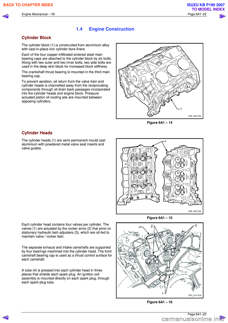
Cylinder Block
The cylinder block (1) is constructed from aluminium alloy
with cast-in-place iron cylinder bore liners.
Each of the four copper-inf iltrated sintered steel main
bearing caps are attached to the cylinder block by six bolts.
Along with two outer and two inner bolts, two side bolts are
used in the deep skirt block fo r increased block stiffness.
The crankshaft thrust bearing is mounted in the third main
bearing cap.
To prevent aeration, oil retu rn from the valve train and
cylinder heads is channelled away from the reciprocating
components through oil drain back passages incorporated
into the cylinder heads and engine block. Pressure
actuated piston oil cooling jets are mounted between
opposing cylinders.
Figure 6A1 – 14
Cylinder Heads
The cylinder heads (1) are semi-permanent mould cast
aluminium with powdered metal valve seat inserts and
valve guides.
Figure 6A1 – 15
Each cylinder head contains four valves per cylinder. The
valves (1) are actuated by the rocker arms (2) that pivot on
stationary hydraulic lash adjuste rs (3), which are oil-fed to
maintain valve / rocker lash.
The separate exhaust and intake camshafts are supported
by four bearings machined into the cylinder head. The front
camshaft bearing cap is used as a thrust control surface for
each camshaft.
A tube (4) is pressed into each cylinder head in three
places that shields each spark plug. An ignition coil
assembly is mounted directly on each spark plug, through
each spark plug tube.
Figure 6A1 – 16
BACK TO CHAPTER INDEX
TO MODEL INDEX
ISUZU KB P190 2007
Page 2801 of 6020
Engine Mechanical – V6 Page 6A1–24
Page 6A1–24
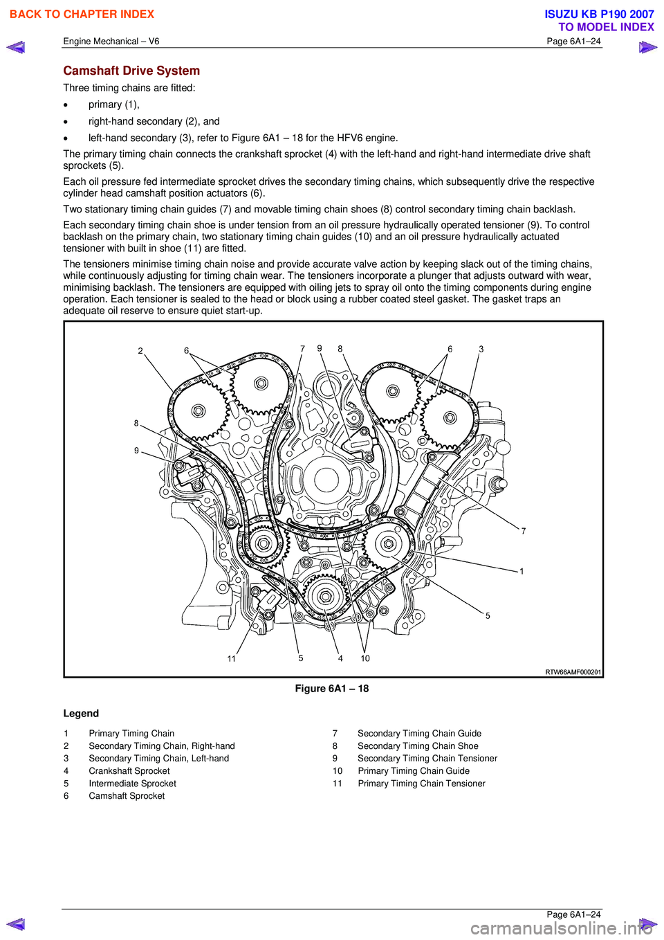
Camshaft Drive System
Three timing chains are fitted:
• primary (1),
• right-hand secondary (2), and
• left-hand secondary (3), refer to Figure 6A1 – 18 for the HFV6 engine.
The primary timing chain connects the crankshaft sprocket (4) with the left-hand and right-hand intermediate drive shaft
sprockets (5).
Each oil pressure fed intermediate sprocket drives the se condary timing chains, which subsequently drive the respective
cylinder head camshaft position actuators (6).
Two stationary timing chain guides (7) and movable timing c hain shoes (8) control secondary timing chain backlash.
Each secondary timing chain shoe is under tension from an oil pressure hydraulically operated tensioner (9). To control
backlash on the primary chain, two st ationary timing chain guides (10) and an oil pressure hydraulically actuated
tensioner with built in shoe (11) are fitted.
The tensioners minimise timing chain noise and provide accura te valve action by keeping slack out of the timing chains,
while continuously adjusting for timing chain wear. The tensioners incorporate a plunger that adjusts outward with wear,
minimising backlash. The tensioners are equipped with oiling jets to spray oil onto the timing components during engine
operation. Each tensioner is sealed to the head or block using a rubber coated steel gasket. The gasket traps an
adequate oil reserve to ens ure quiet start-up.
Figure 6A1 – 18
Legend
1 Primary Timing Chain
2 Secondary Timing Chain, Right-hand
3 Secondary Timing Chain, Left-hand
4 Crankshaft Sprocket
5 Intermediate Sprocket
6 Camshaft Sprocket 7 Secondary Timing Chain Guide
8 Secondary Timing Chain Shoe
9 Secondary Timing Chain Tensioner
10 Primary Timing Chain Guide
11 Primary Timing Chain Tensioner
BACK TO CHAPTER INDEX
TO MODEL INDEX
ISUZU KB P190 2007