2007 ISUZU KB P190 battery
[x] Cancel search: batteryPage 3191 of 6020
Engine Cooling – V6 Engine Page 6B1–56
Reinstall
Installation of the radiator is the reverse of removal procedures, noting the following points:
1 Before installing radiator, inspect core to ensure that there is no foreign matter in core fins. Clean out between core fins with compressed air, blowing from rear to front.
2 If the vehicle is fitted with an automatic transmission, remove plugs from the removed cooling pipe ends and the two quick connect fittings.
3 After wiping cooler line ends and smearing clean automatic transmission fluid over each flared line end, push into the quick connect fitting to engage. As a security check, tug on each line to ensure correct engagement.
4 Check the transmission fluid level. Refer to the following references as required:
• 7C4 Automatic Transmission
• 4L60E On-vehicle Servicing
5 Install the following hoses:
a. Lower radiator hose, securing with the hose clamp.
b. Upper radiator hose, securing with the hose clamp.
6 Install the radiator cooling fan and shroud assembly. Refer to 3.13Cooling Fan and Shroud Assembly in this Section. Ensure that electrical connectors and the transmission cooler lines are seated correctly in the integral
retainer clips before install upper radiator shroud.
7 Refill cooling system. Refer to 3.3 Draining and Filling Cooling System in this Section.
8 Check for coolant leaks. Refer to 3.7 Pressure Testing in this Section.
9 Reconnect battery ground lead. Refer to 8A Electrical Body & Chassis.
10 Check cooling fan operation. Refer to 6C1-2 Engine Management Diagnostics. Also check for correct rotational direction of cooling fan.
BACK TO CHAPTER INDEX
TO MODEL INDEX
ISUZU KB P190 2007
Page 3205 of 6020
Fuel System – V6 Page 6C – 3
1 General Information
Description
Fuel is injected into the engine by separate fuel injectors that are mounted in the intake manifold (common chamber).
Fuel is supplied to the injectors under pressure from the fuel tank through the fuel lines and the fuel rail, which is
attached to the top of the common chamber.
A fuel pressure control valve is installed on the fuel rail to maintain fuel line pressure across the injectors under all
operating conditions. Fuel pressure is maintained by controlling the amount of fuel that is supplied from the fuel tank,
based on the demand of the engine via the engine control module (ECM).
Two interchangeable “O” rings are used on the fuel injector and must be replaced when the injectors are removed.
The Multiport Fuel Injection system utilizes an injection system where the injectors turn on at every crankshaft revolution.
The ECM controls the injector on time so that the correct amount of fuel is metered depending on driving conditions.
The V6 engine is designed to use only unleaded petrol.
Unleaded petrol must be used for correct emission control system operation and its use will also minimize spark plug
fouling and extend engine oil life.
Using leaded petrol can damage the emission control system and could void the vehicle warranty. All vehicles are
equipped with an Evaporative Emission Control System. The purpose of the system is to minimize the escape of fuel
vapours into the atmosphere.
Service Precautions
• Use extreme care when working on the fuel system and follow all safety precautions.
• W hen working on the fuel system, disconnect the battery ground cable except for tests where battery voltage is
required.
• Always keep a dry chemical (class B) fire extinguisher near the work area.
• Relace all fuel lines and fittings with the same type of line and fitting as those removed.
• Clean and inspect “O” rings carefully and replace if required.
• Always depressurize the fuel lines before servicing any fuel system components.
• Do not attempt any repairs on the fuel system until, all warnings and instructions, relating to that repair have been
read and ensure all notices and cautions are adhered to.
• Do not allow any naked frames or sparks near the work area when working on the fuel system.
• If draining of the fuel system is required, this should be done in a well ventilated area.
• Protect the fuel lines and associated parts from thermal damage, spattering when welding.
BACK TO CHAPTER INDEX
TO MODEL INDEX
ISUZU KB P190 2007
Page 3217 of 6020
Fuel System – V6 Page 6C – 15
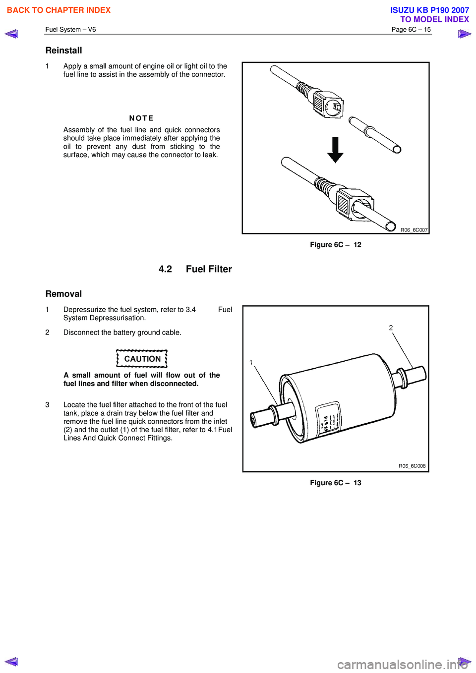
Reinstall
1 Apply a small amount of engine oil or light oil to the
fuel line to assist in the assembly of the connector.
NOTE
Assembly of the fuel line and quick connectors
should take place immediately after applying the
oil to prevent any dust from sticking to the
surface, which may cause the connector to leak.
Figure 6C – 12
4.2 Fuel Filter
Removal
1 Depressurize the fuel system, refer to 3.4 Fuel
System Depressurisation.
2 Disconnect the battery ground cable.
A small amount of fuel will flow out of the
fuel lines and filter when disconnected.
3 Locate the fuel filter attached to the front of the fuel tank, place a drain tray below the fuel filter and
remove the fuel line quick connectors from the inlet
(2) and the outlet (1) of the fuel filter, refer to 4.1 Fuel
Lines And Quick Connect Fittings.
Figure 6C – 13
BACK TO CHAPTER INDEX
TO MODEL INDEX
ISUZU KB P190 2007
Page 3232 of 6020
Fuel System – V6 Page 6C – 30
4.7 Fuel Tank Siphon Procedure
• Fuel vapour remains in the modular fuel
pump and sender assembly and fuel lines
that can be spilled during service
operations. Ensure no naked flames or
other ignition sources are nearby. Ensure
all cellular phones (and transmission
devices that may cause any metal objects
to become unintentional receiving
antennas) are switched off.
• Place a dry chemical (Class B) fire
extinguisher nearby before performing any
on-vehicle service procedures. Failure to
follow these precautions may result in
personal injury.
For an exploded view of fuel tank components, refer Figure 6C – 17.
1 Depressurise the fuel system, refer to 3.4 Fuel System Depressurisation.
2 Reinstall the fuel pump relay, refer to 8A Electrical Body and Chassis.
Disconnecting the battery affects certain
vehicle electronic systems. 1.1 WARNING,
CAUTION and NOTES.
3 Disconnect the negative battery terminal.
4 Remove the fuel filler cap.
NOTE
Lubricate the fuel siphon hose with J36850
TransJel Transmission Assembly Lubricant or
equivalent to aid hose insertion. Use only an
approved lubricant.
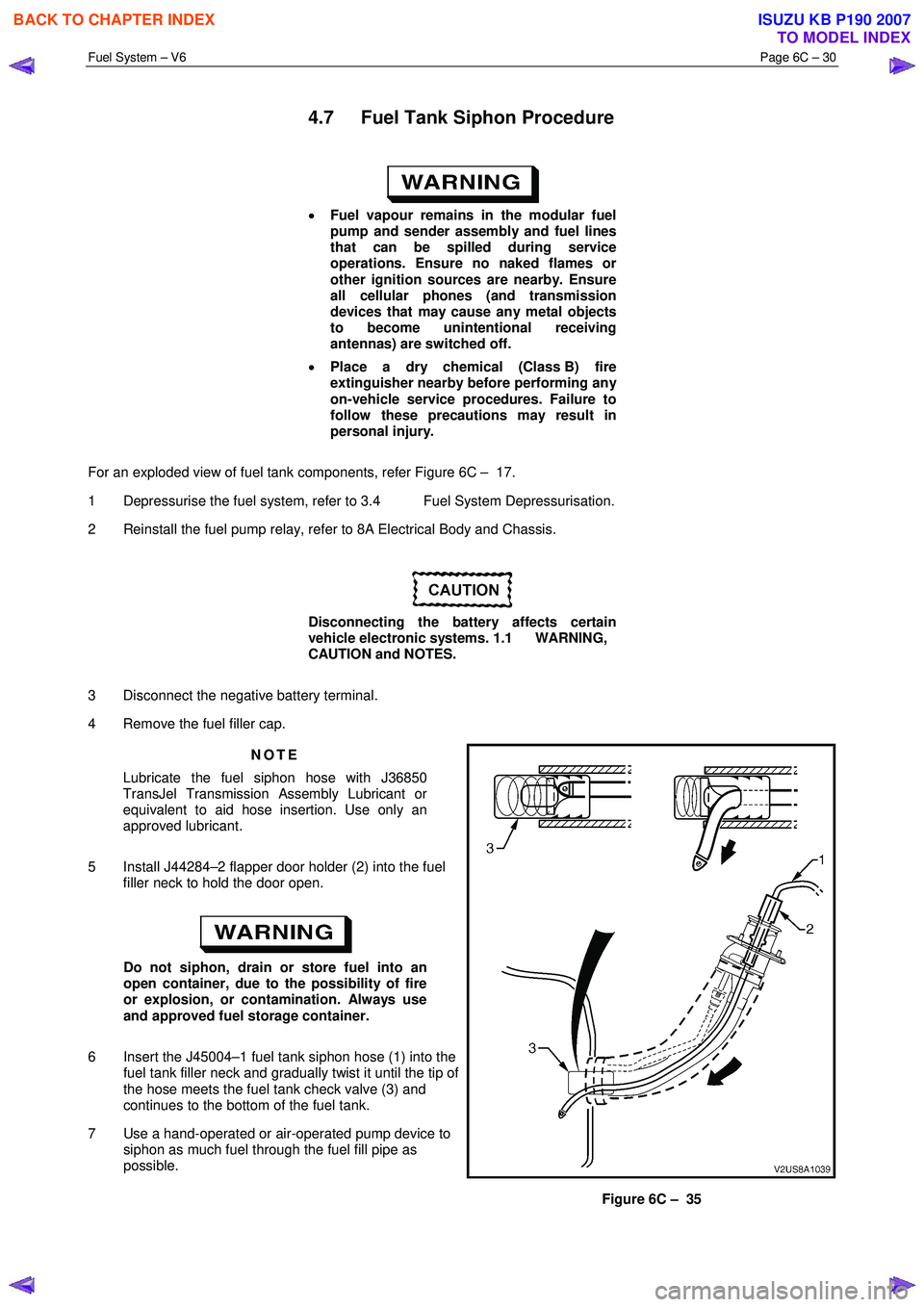
5 Install J44284–2 flapper door holder (2) into the fuel filler neck to hold the door open.
Do not siphon, drain or store fuel into an
open container, due to the possibility of fire
or explosion, or contamination. Always use
and approved fuel storage container.
6 Insert the J45004–1 fuel tank siphon hose (1) into the fuel tank filler neck and gradually twist it until the tip of
the hose meets the fuel tank check valve (3) and
continues to the bottom of the fuel tank.
7 Use a hand-operated or air-operated pump device to siphon as much fuel through the fuel fill pipe as
possible.
Figure 6C – 35
BACK TO CHAPTER INDEX
TO MODEL INDEX
ISUZU KB P190 2007
Page 3243 of 6020
Engine Management – V6 – General Information Page 6C1-1–1
6C1-1 Engine Management – V6
General Information
ATTENTION
Before performing any service operation or other procedure described in this Section, refer to 1.3 Warning
Caution and Notes for correct workshop practices with regard to safety and / or property damage.
1 General Information ............................................................................................................ ...................3
1.1 Introduction ............................................................................................................................................................ 3
1.2 Emission Control ................................................................................................................................................... 3
ADR 79/01 Emissions Standards .......................................................................................................................... 3
1.3 Warning Caution and Notes .................................................................................................................................. 4
Definition of WARNING, CAUTION and NOTE Statements ............................................................................. .... 4
WARNING defined ............................................................................................................................................. 4
CAUTION defined .............................................................................................................................................. 4
NOTE defined..................................................................................................................................................... 4
2 Component Locations ............................................................................................................ ...............5
2.1 Cylinder Numbering............................................................................................................................................... 5
2.2 Engine Compartment............................................................................................................................................. 5
2.3 Engine ..................................................................................................................................................................... 6
2.4 Interior..................................................................................................................................................................... 8
3 System Operation ...................................................................................................................................9
3.1 Fuel Delivery System ............................................................................................................................................. 9
Fuel System Pressure ........................................................................................................... ................................ 9
Fuel Injection System .......................................................................................................................................... 10
Short Term Fuel Trim ....................................................................................................................................... 10
Long Term Fuel Trim ........................................................................................................................................ 10
3.2 Air / Fuel Control System ...................................................................................................... .............................. 11
Starting Mode ....................................................................................................................................................... 11
Run Mode.............................................................................................................................................................. 11
Open Loop Mode................................................................................................................. ............................. 11
Closed Loop Mode ............................................................................................................... ............................ 11
Acceleration Mode .............................................................................................................. ................................. 11
Deceleration Mode ............................................................................................................................................... 11
Fuel Shut-off Mode .............................................................................................................................................. 11
Battery Voltage Correction Mode ................................................................................................ ....................... 12
Limp Mode ............................................................................................................................................................ 12
Engine Protection Mode ......................................................................................................... ............................. 12
Clear Flood Mode ................................................................................................................................................. 12
3.3 Ignition Control System........................................................................................................ ............................... 12
3.4 Starter Motor Operation....................................................................................................................................... 12
3.5 Throttle Actuator Control System ............................................................................................... ....................... 12
Description ........................................................................................................................................................... 12
Throttle Body Relearn Procedure ....................................................................................................................... 14
TAC System Default Actions / Reduce Power Modes................................................................................ ....... 14
Forced Engine Shutdown .................................................................................................................................... 14
3.6 Cruise Control System ........................................................................................................................................ 14
3.7 Brake Torque Management ........................................................................................................ ......................... 15
3.8 Emission Control Systems.................................................................................................................................. 15
Evaporative Emission Control System ............................................................................................ .................. 15
Engine Ventilation System .................................................................................................................................. 16
BACK TO CHAPTER INDEX
TO MODEL INDEX
ISUZU KB P190 2007
Page 3254 of 6020
Engine Management – V6 – General Information Page 6C1-1–12
Battery Voltage Correction Mode
The ECM monitors the battery voltage circuit to ensure the voltage available to the engine management system stays
within the specified range. A low system voltage changes the voltage across the fuel injectors, which affects the fuel
injector flow rate. In addition, a low system voltage fault condition may cause other engine management system
components to malfunction.
The ECM switches to battery voltage correction mode when the ECM detects a low battery voltage fault condition. W hile
in battery voltage correction mode, the ECM performs the following functions to compensate for the low system voltage:
• Increases the injector on-time to maintain the correct amount of fuel being delivered, and
• Increases the idle speed to increase the generator output.
Limp Mode
The programming in the ECM software allows the engine to run in a back-up fuel strategy or limp mode when the ECM
fails to receive signal inputs from critical sensors or when a critical engine management fault condition exists.
The ECM switches to limp mode to enable the vehicle to be driven until service operations can be performed.
Engine Protection Mode
Engine protection mode is engaged to protect engine components from friction damage in the event of an engine over-
temperature condition being detected by the ECM.
W hen the ECM is in engine protection mode, fuel injectors are systematically disabled and re-activated. The injectors
that have been shut down allow the air being drawn into the engine to assist with engine cooling.
Clear Flood Mode
If the engine is flooded with fuel during starting and will not start, the clear flood mode can be manually selected by
depressing the accelerator pedal to wide open throttle (W OT). In this mode, the ECM will completely disable the fuel
injectors, and will maintain this state during engine cranking as long as the ECM detects a W OT condition with engine
speed less than 1,000 rpm.
3.3 Ignition Control System
The electronic ignition system provides a spark to ignite the compressed air / fuel mixture at the correct time. The ECM
maintains correct spark timing and dwell for all engine operating conditions. The ECM calculates the optimum spark
parameters from information received from the various sensors and triggers the appropriate ignition module / coil to fire
the spark plug.
3.4 Starter Motor Operation
The engine control module controls the activation of the start relay in response to inputs from:
• Ignition switch,
• Battery,
• Immobiliser system, and
• Automatic transmission gear selector position / clutch pedal position switch for vehicles with manual transmissions.
3.5 Throttle Actuator Control System
Description
The throttle actuator control (TAC) system is used to improve emissions, fuel economy and driveability. The TAC system
eliminates the mechanical link between the accelerator pedal and the throttle plate and eliminates the need for a cruise
control module and idle air control motor. The TAC system comprises of:
BACK TO CHAPTER INDEX
TO MODEL INDEX
ISUZU KB P190 2007
Page 3255 of 6020
Engine Management – V6 – General Information Page 6C1-1–13
• The accelerator pedal assembly which includes:
− The accelerator pedal,
− The accelerator pedal position (APP) sensor
one, and
− The accelerator pedal position (APP) sensor two.
Figure 6C1-1 – 7
To avoid serious personal injury, never
attempt to rotate the throttle plate manually
whilst the throttle body harness connector is
connected to the throttle body.
• The throttle body assembly which includes:
− the throttle position (TP) sensor one
− the throttle position (TP) sensor two
− the throttle actuator control (TAC) motor, and
− the throttle plate.
• The engine control module (ECM).
Figure 6C1-1 – 8
The ECM monitors the accelerator pedal position through the two APP sensors and processes this information, along
with other system sensor inputs, to command the throttle plate to a certain position.
The throttle plate is controlled by a direct current motor called the throttle actuator control motor. The ECM operates this
motor in the forward or reverse direction by controlling battery voltage and / or ground to two internal drivers. The throttle
plate is held at a rest position of seven percent open using a constant force return spring. This spring holds the throttle
plate to the rest position when there is no current flowing to the actuator motor.
The ECM monitors the throttle plate angle through two TP sensors. Using this information, the ECM can precisely adjust
the throttle plate.
The ECM performs diagnostics that monitor the voltage levels of both APP sensors, both TP sensors and the throttle
actuator control motor circuit. It also monitors the spring return rate. These diagnostics are performed at different times
based on whether the engine is running, not running, or whether the ECM is currently in a throttle body relearn procedure.
Two sensors within the accelerator pedal assembly and throttle body assembly are used to provide redundancy. If a
malfunction is detected, the throttle plate is moved to a pre-determined position.
Every ignition cycle, the ECM performs a quick throttle return spring test to ensure the throttle plate can return to the
seven percent rest position from the zero percent position. This is to ensure the throttle plate can be brought to the rest
position in case of an actuator motor circuit failure.
BACK TO CHAPTER INDEX
TO MODEL INDEX
ISUZU KB P190 2007
Page 3256 of 6020
Engine Management – V6 – General Information Page 6C1-1–14
Throttle Body Relearn Procedure
The ECM stores values that include the lowest possible TP sensor positions (zero percent), the rest positions (seven
percent), and the spring return rate. These values will only be erased or overwritten if the ECM is reprogrammed or if a
throttle body relearn procedure is performed.
NOTE
If the battery has been disconnected, the ECM
performs a throttle body relearn procedure once
the battery has been reconnected and the ignition
turned on.
The ECM performs a throttle body relearn procedure anytime the ignition is turned on and the following conditions have
been met:
• The engine has been off for greater than 29 seconds,
• The engine speed is less than 40 rpm,
• The vehicle speed is 0 km/h,
• The engine coolant temperature (ECT) is 5 – 60°C; if Tech 2 is used to perform the relearn procedure, the ECT is
5 – 100°C,
• The intake air temperature (IAT) is greater than 5 – 60°C; if Tech 2 is used to perform the relearn procedure, the
IAT is 5 – 100°C,
• The APP sensor angle is less than 15 percent, and
• Ignition voltage is greater than 10 V.
The throttle body relearn procedure is performed 29 seconds after the ignition is turned on. The ECM commands the
throttle plate from the rest position (seven percent open) to full closed (zero percent), then to around 10 percent open.
This procedure takes about six – eight seconds. If any faults occur in the TAC system, a DTC sets. At the start of this
procedure, the Tech 2 TAC Learn Counter parameter should display 0, then count up to 11 after the procedure is
completed. If the counter did not start at 0, or if the counter did not end at 11, a fault has occurred and a DTC should set.
TAC System Default Actions / Reduce Power Modes
The ECM switches to the following reduce power modes if the ECM detects a fault condition in the TAC system:
• If an APP sensor circuit fault or TP sensor circuit fault is detected, the ECM limits engine torque so the vehicle
cannot reach speeds of greater than 100 km/h. The ECM remains in this reduce power mode during the entire
ignition cycle, even if the fault is corrected.
• If there is a fault condition with the throttle actuator control circuits, a throttle actuator command vs. actual position
fault, a return spring check fault, or a TP sensor one circuit fault, the ECM limits engine speed to 2500 rpm and
three – six fuel injectors are randomly disabled. At this time the reduce power indicator is commanded on. The
ECM remains in the reduce power mode during the entire ignition cycle even if the fault is corrected.
NOTE
If a TP sensor one or throttle actuator control
circuit fault is present at the time the vehicle is at
idle, with no accelerator pedal angle, the engine
may stall.
Forced Engine Shutdown
A further safety feature which is built into the TAC system is the ECM will initiate an engine shut down if, the ECM’s
internal monitoring functions detects a serious internal fault, the fuel injectors will be turned off.
3.6 Cruise Control System
The cruise control system integrates with the engine control module (ECM) through the powertrain interface module
(PIM), to control the electronic throttle actuator and maintain the vehicle at the speed set by the driver.
BACK TO CHAPTER INDEX
TO MODEL INDEX
ISUZU KB P190 2007