2007 ISUZU KB P190 battery
[x] Cancel search: batteryPage 3438 of 6020
Engine Management – V6 – Diagnostics Page 6C1-2–160
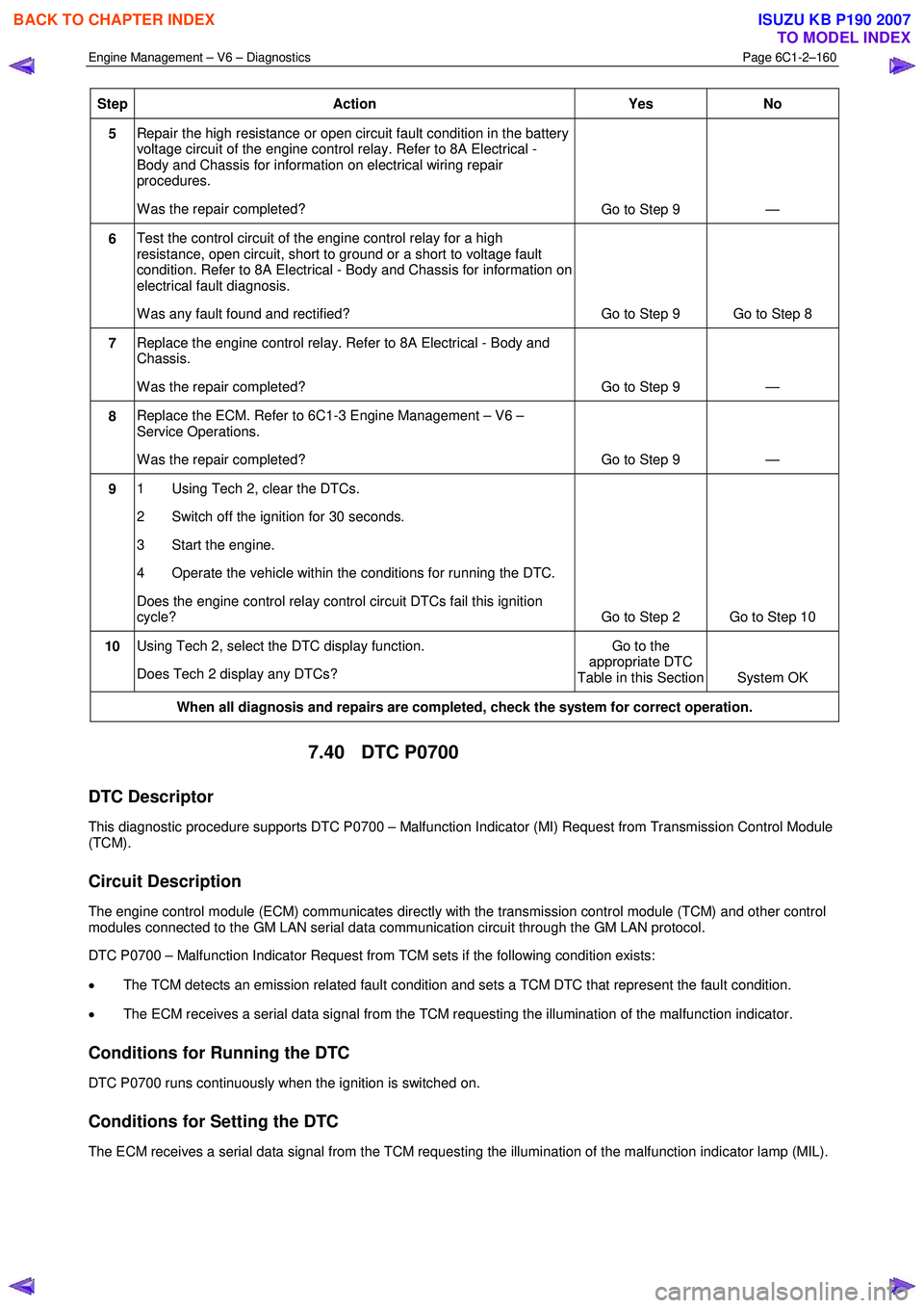
Step Action Yes
No
5 Repair the high resistance or open circuit fault condition in the battery
voltage circuit of the engine control relay. Refer to 8A Electrical -
Body and Chassis for information on electrical wiring repair
procedures.
W as the repair completed? Go to Step 9 —
6 Test the control circuit of the engine control relay for a high
resistance, open circuit, short to ground or a short to voltage fault
condition. Refer to 8A Electrical - Body and Chassis for information on
electrical fault diagnosis.
W as any fault found and rectified? Go to Step 9 Go to Step 8
7 Replace the engine control relay. Refer to 8A Electrical - Body and
Chassis.
W as the repair completed? Go to Step 9 —
8 Replace the ECM. Refer to 6C1-3 Engine Management – V6 –
Service Operations.
W as the repair completed? Go to Step 9 —
9 1 Using Tech 2, clear the DTCs.
2 Switch off the ignition for 30 seconds.
3 Start the engine.
4 Operate the vehicle within the conditions for running the DTC.
Does the engine control relay control circuit DTCs fail this ignition
cycle? Go to Step 2 Go to Step 10
10 Using Tech 2, select the DTC display function.
Does Tech 2 display any DTCs? Go to the
appropriate DTC
Table in this Section System OK
When all diagnosis and repairs are completed, check the system for correct operation.
7.40 DTC P0700
DTC Descriptor
This diagnostic procedure supports DTC P0700 – Malfunction Indicator (MI) Request from Transmission Control Module
(TCM).
Circuit Description
The engine control module (ECM) communicates directly with the transmission control module (TCM) and other control
modules connected to the GM LAN serial data communication circuit through the GM LAN protocol.
DTC P0700 – Malfunction Indicator Request from TCM sets if the following condition exists:
• The TCM detects an emission related fault condition and sets a TCM DTC that represent the fault condition.
• The ECM receives a serial data signal from the TCM requesting the illumination of the malfunction indicator.
Conditions for Running the DTC
DTC P0700 runs continuously when the ignition is switched on.
Conditions for Setting the DTC
The ECM receives a serial data signal from the TCM requesting the illumination of the malfunction indicator lamp (MIL).
BACK TO CHAPTER INDEX
TO MODEL INDEX
ISUZU KB P190 2007
Page 3512 of 6020
Engine Management – V6 – Diagnostics Page 6C1-2–234
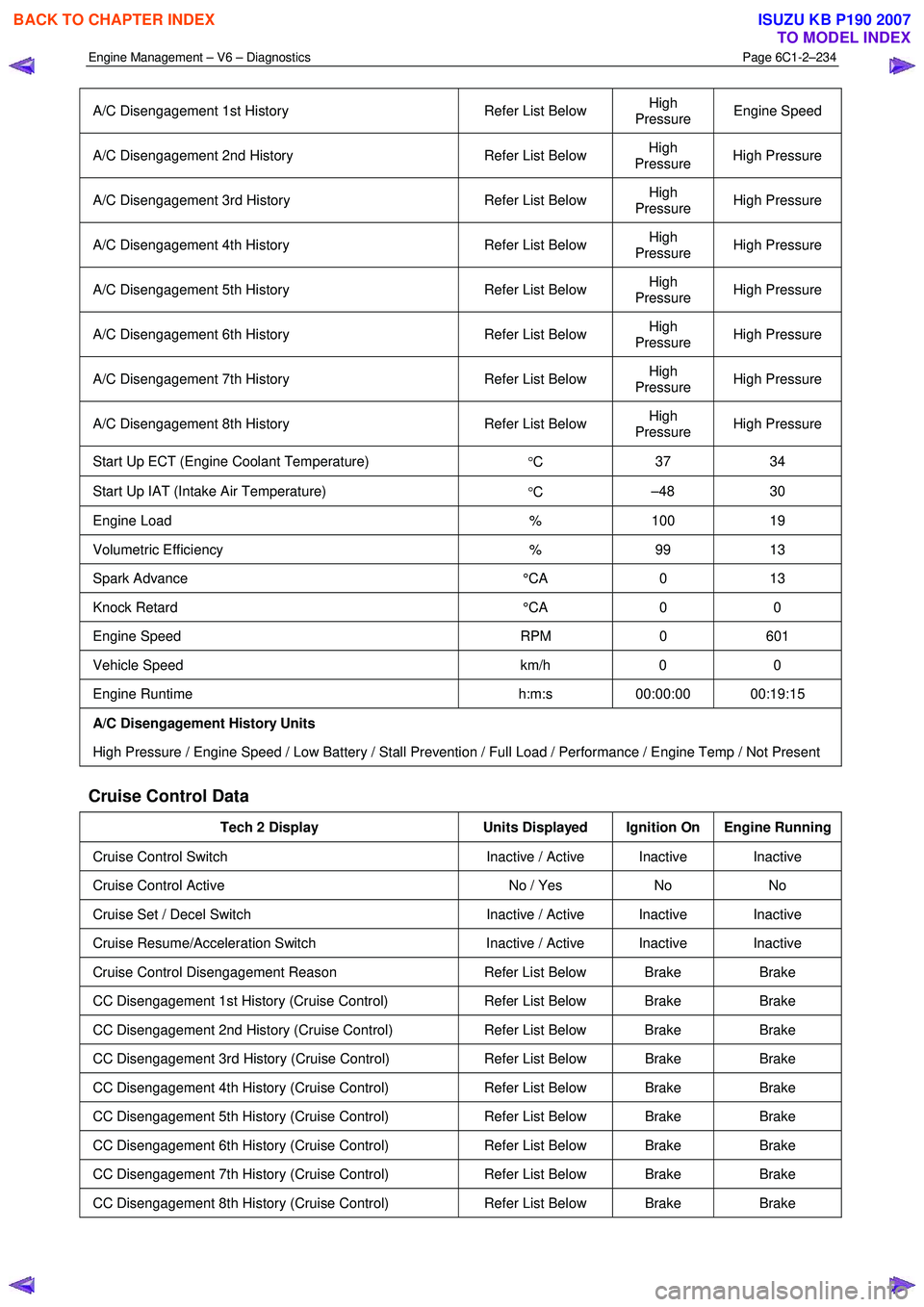
A/C Disengagement 1st History Refer List Below High
Pressure Engine Speed
A/C Disengagement 2nd History
Refer List Below High
Pressure High Pressure
A/C Disengagement 3rd History
Refer List Below High
Pressure High Pressure
A/C Disengagement 4th History
Refer List Below High
Pressure High Pressure
A/C Disengagement 5th History
Refer List Below High
Pressure High Pressure
A/C Disengagement 6th History
Refer List Below High
Pressure High Pressure
A/C Disengagement 7th History
Refer List Below High
Pressure High Pressure
A/C Disengagement 8th History
Refer List Below High
Pressure High Pressure
Start Up ECT (Engine Coolant Temperature)
°C 37 34
Start Up IAT (Intake Air Temperature)
°C –48 30
Engine Load
% 100 19
Volumetric Efficiency % 99 13
Spark Advance °CA 0 13
Knock Retard °CA 0 0
Engine Speed RPM 0 601
Vehicle Speed km/h 0 0
Engine Runtime h:m:s 00:00:00 00:19:15
A/C Disengagement History Units
High Pressure / Engine Speed / Low Battery / Stall Prevention / Full Load / Performance / Engine Temp / Not Present
Cruise Control Data
Tech 2 Display Units Displayed Ignition On Engine Running
Cruise Control Switch Inactive / Active Inactive Inactive
Cruise Control Active No / Yes No No
Cruise Set / Decel Switch Inactive / Active Inactive Inactive
Cruise Resume/Acceleration Switch Inactive / Active Inactive Inactive
Cruise Control Disengagement Reason Refer List Below Brake Brake
CC Disengagement 1st History (Cruise Control) Refer List Below Brake Brake
CC Disengagement 2nd History (Cruise Control) Refer List Below Brake Brake
CC Disengagement 3rd History (Cruise Control) Refer List Below Brake Brake
CC Disengagement 4th History (Cruise Control) Refer List Below Brake Brake
CC Disengagement 5th History (Cruise Control) Refer List Below Brake Brake
CC Disengagement 6th History (Cruise Control) Refer List Below Brake Brake
CC Disengagement 7th History (Cruise Control) Refer List Below Brake Brake
CC Disengagement 8th History (Cruise Control) Refer List Below Brake Brake
BACK TO CHAPTER INDEX
TO MODEL INDEX
ISUZU KB P190 2007
Page 3516 of 6020
Engine Management – V6 – Diagnostics Page 6C1-2–238
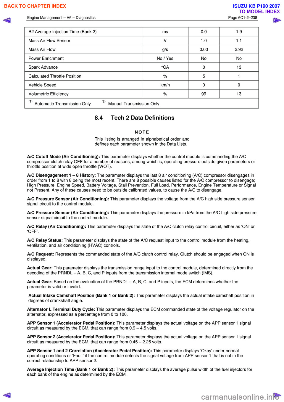
B2 Average Injection Time (Bank 2) ms 0.0 1.9
Mass Air Flow Sensor V 1.0 1.1
Mass Air Flow g/s 0.00 2.92
Power Enrichment No / Yes No No
Spark Advance °CA 0 13
Calculated Throttle Position % 5 1
Vehicle Speed km/h 0 0
Volumetric Efficiency % 99 13
(1) Automatic Transmission Only (2) Manual Transmission Only
8.4 Tech 2 Data Definitions
NOTE
This listing is arranged in alphabetical order and
defines each parameter shown in the Data Lists.
A/C Cutoff Mode (Air Conditioning): This parameter displays whether the control module is commanding the A/C
compressor clutch relay OFF for a number of reasons, among which is; operating pressure outside given parameters or
throttle position at wide open throttle (W OT).
A/C Disengagement 1 – 8 History: The parameter displays the last 8 air conditioning (A/C) compressor disengages in
order from 1 to 8 with 8 being the most recent. There are 8 possible causes listed for the A/C compressor to disengage;
High Pressure, Engine Speed, Battery Voltage, Stall Prevention, Full Load, Performance, Engine Temperature or Signal
not Present. Any of these causes need to be outside calibrated values, to cause the A/C to disengage.
A/C Pressure Sensor (Air Conditioning): This parameter displays the voltage from the A/C high side pressure sensor
signal circuit to the control module.
A/C Pressure Sensor (Air Conditioning): This parameter displays the pressure in kPa from the A/C high side pressure
sensor signal circuit to the control module.
A/C Relay (Air Conditioning): This parameter displays the state of the A/C clutch relay control circuit, either as ‘ON’ or
‘OFF’.
A/C Relay Status: This parameter displays the state of the A/C request input to the control module from the heating,
ventilation, and air conditioning (HVAC) controls.
A/C Request: Represents the commanded state of the A/C clutch control relay. Clutch should be engaged when ON is
displayed.
Actual Gear: This parameter displays the transmission range input to the control module, determined directly from the
decoding of the PRNDL – A, B, C, and P inputs from the transmission internal mode switch (IMS).
Actual Gear: Based on the evaluation of the PRNDL – A, B, C, and P inputs, the ECM determines whether the
parameter is valid or invalid.
Actual Intake Camshaft Position (Bank 1 or Bank 2): This parameter displays the actual intake camshaft position in
degrees of crankshaft angle.
Alternator L Terminal Duty Cycle: This parameter displays the ECM commanded state of the voltage regulator on the
alternator, expressed as a percentage from 0 to 100.
APP Sensor 1 (Accelerator Pedal Position): This parameter displays the actual voltage on the APP sensor 1 signal
circuit as measured by the ECM, that can range from 0.9 – 4.5 volts.
APP Sensor 2 (Accelerator Pedal Position): This parameter displays the actual voltage on the APP sensor 1 signal
circuit as measured by the ECM, that can range from 0.45 – 2.25 volts.
APP Sensor 1 and 2 Correlation (Accelerator Pedal Position): This parameter displays ‘Okay’ under normal
operating conditions or ‘Fault’ if the control module detects the signal voltage from APP sensor 1 that is not in the
correct relationship to APP sensor 2.
Average Injection Time (Bank 1 or Bank 2): This parameter displays the average pulse width of the fuel injectors for
each bank of the engine as determined by the ECM.
BACK TO CHAPTER INDEX
TO MODEL INDEX
ISUZU KB P190 2007
Page 3528 of 6020
Engine Management – V6 – Service Operations Page 6C1-3–4
1 General Information
1.1 General Description
This Section describes the correct service procedures to repair and test components of the V6 engine management
system. Emphasis is placed on the proper procedures and repair of components related to this specific system.
For component description, operation and location, refer to 6C1-1 Engine Management – V6 – General Information.
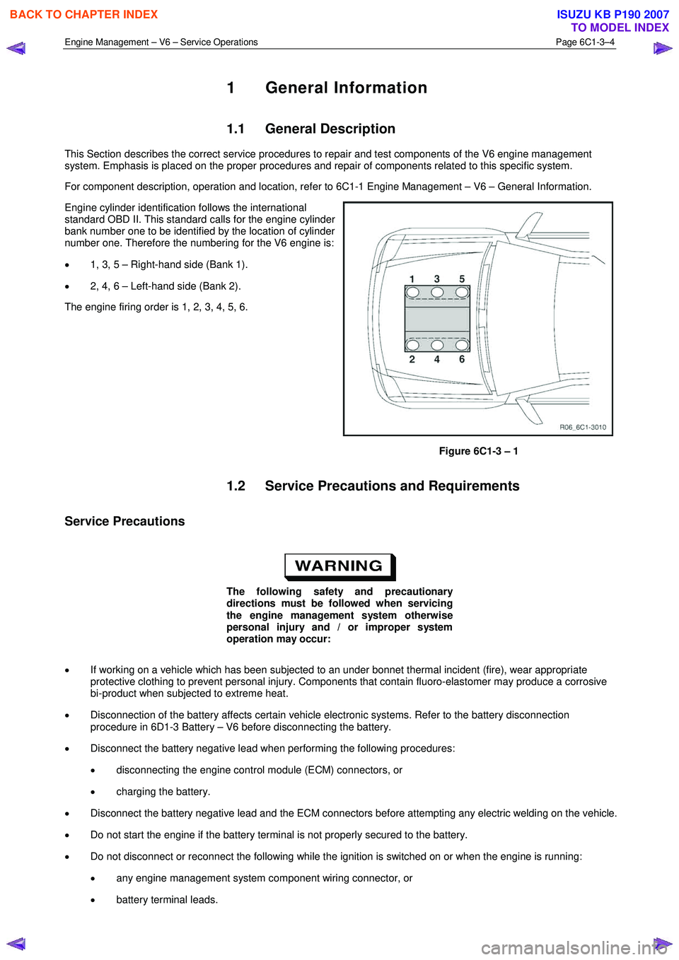
Engine cylinder identification follows the international
standard OBD II. This standard calls for the engine cylinder
bank number one to be identified by the location of cylinder
number one. Therefore the numbering for the V6 engine is:
• 1, 3, 5 – Right-hand side (Bank 1).
• 2, 4, 6 – Left-hand side (Bank 2).
The engine firing order is 1, 2, 3, 4, 5, 6.
Figure 6C1-3 – 1
1.2 Service Precautions and Requirements
Service Precautions
The following safety and precautionary
directions must be followed when servicing
the engine management system otherwise
personal injury and / or improper system
operation may occur:
• If working on a vehicle which has been subjected to an under bonnet thermal incident (fire), wear appropriate
protective clothing to prevent personal injury. Components that contain fluoro-elastomer may produce a corrosive
bi-product when subjected to extreme heat.
• Disconnection of the battery affects certain vehicle electronic systems. Refer to the battery disconnection
procedure in 6D1-3 Battery – V6 before disconnecting the battery.
• Disconnect the battery negative lead when performing the following procedures:
• disconnecting the engine control module (ECM) connectors, or
• charging the battery.
• Disconnect the battery negative lead and the ECM connectors before attempting any electric welding on the vehicle.
• Do not start the engine if the battery terminal is not properly secured to the battery.
• Do not disconnect or reconnect the following while the ignition is switched on or when the engine is running:
• any engine management system component wiring connector, or
• battery terminal leads.
BACK TO CHAPTER INDEX
TO MODEL INDEX
ISUZU KB P190 2007
Page 3529 of 6020
Engine Management – V6 – Service Operations Page 6C1-3–5
• Ensure the correct procedure for disconnecting and connecting engine management system wiring connectors is
always followed.
• Ensure that all wiring connectors are fitted correctly.
• The engine management system wiring connectors are designed to fit only one way; there are indexing tabs and
slots on both halves of the connector. Forcing the connector into place is not necessary if it is being installed with
the correct orientation. Failure to take care to match the indexing tabs and slots correctly can cause damage to the
connector, the module, or other vehicle components or systems.
• Never touch the connector pins of any electronic component, such as an ECM, as electrostatic discharge (ESD)
damage may result.
• W hen steam or pressure cleaning engines, do not direct the cleaning nozzle at engine management system
components.
• Never subject the ECM to temperatures less than -40 ° C and greater than 125 ° C.
• Prior to disconnection or removal of any components associated with the fuel system, clean the area around any
connection points to avoid possible contamination of the fuel system.
• A depressurised fuel system contains fuel in the fuel system and fuel lines that can be spilled during service
operations. To reduce the chance of personal injury, cover the fittings with a shop towel to absorb any fuel spillage
prior to performing the service operation. Once the service operation has been completed, place the towel in an
approved container for disposal.
• To avoid accidental fuel discharge, it is advisable to disconnect the battery and remove the fuel pump relay if the
fuel line between the fuel pump and the fuel rail is to be disconnected / open for an indefinite period.
• Always tighten fasteners to the correct tightening torque, and where indicated in the service procedure, follow the
correct tightening sequence, precautions and recommendations to prevent premature failure of the fastener or
component.
• After removing components, such as the upper or lower intake manifold, front engine pipe, heated oxygen sensor,
etc. always plug any openings to prevent dirt and other contaminants from entering.
• Do not use silicone based assembly lubricants as damage to the heated oxygen sensors may result.
Use of incorrect electrical test equipment
when performing engine management service
procedures could result in incorrect results or
component damage.
• Use only the test equipment specified in the diagnostic tables. Use of other test equipment may either give
incorrect results or damage serviceable components, refer to, 6C1-2 Engine Management – V6 – Diagnostics.
• After completing the required service operations, road test the vehicle to ensure correct engine management
system operation.
Service Requirements
Basic Knowledge Required
A lack of basic understanding of electronics,
electrical wiring circuits and use of electrical
circuit testing tools when performing certain
service procedures could result in incorrect
results or damage to components.
In addition, a general understanding of the engine management system and its component operation is essential to
prevent misdiagnosis and component damage.
BACK TO CHAPTER INDEX
TO MODEL INDEX
ISUZU KB P190 2007
Page 3542 of 6020
Engine Management – V6 – Service Operations Page 6C1-3–18
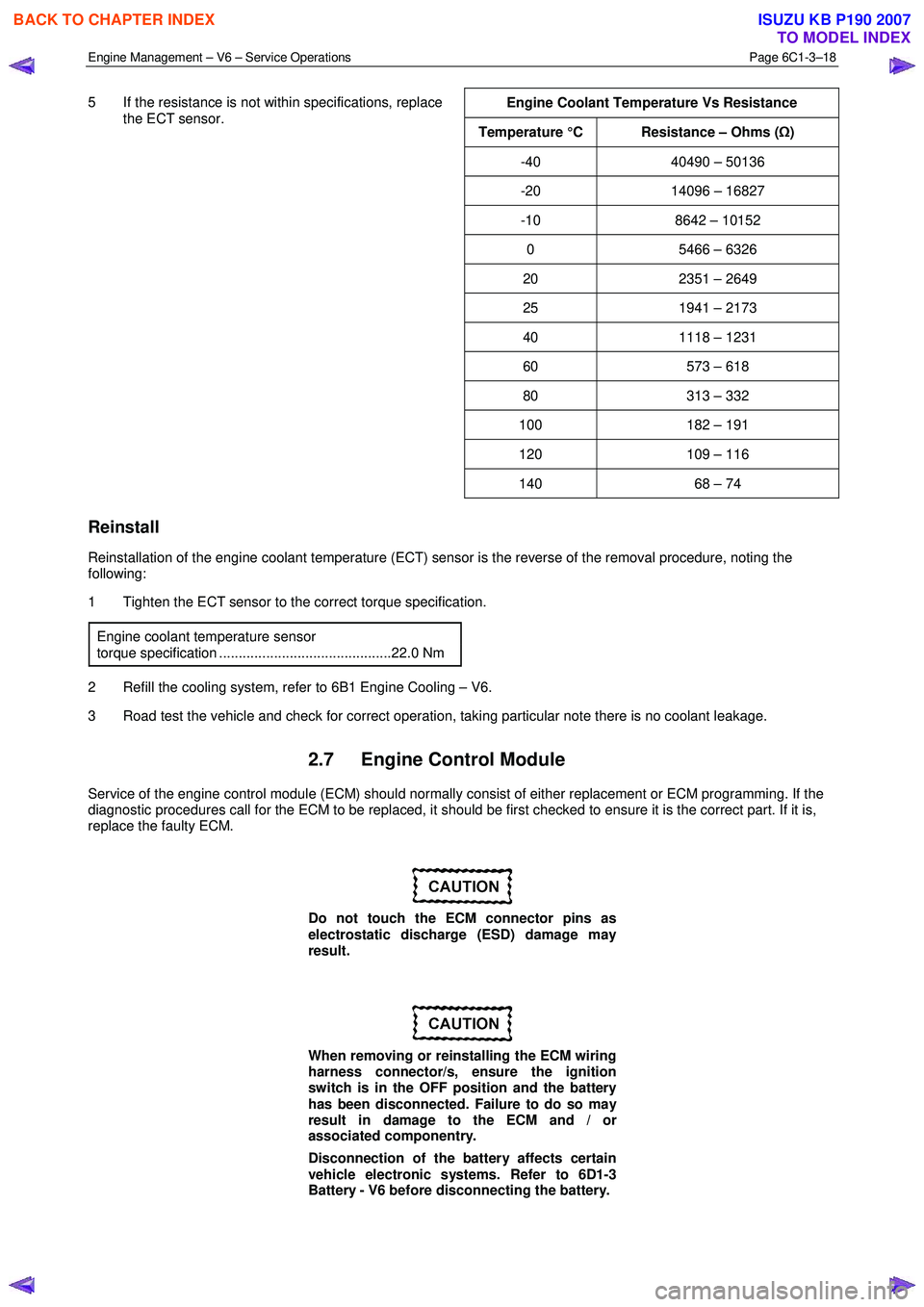
5 If the resistance is not within specifications, replace
the ECT sensor.
Engine Coolant Temperature Vs Resistance
Temperature °C Resistance – Ohms (
Ω)
-40 40490 – 50136
-20 14096 – 16827
-10 8642 – 10152
0 5466 – 6326
20 2351 – 2649
25 1941 – 2173
40 1118 – 1231
60 573 – 618
80 313 – 332
100 182 – 191
120 109 – 116
140 68 – 74
Reinstall
Reinstallation of the engine coolant temperature (ECT) sensor is the reverse of the removal procedure, noting the
following:
1 Tighten the ECT sensor to the correct torque specification.
Engine coolant temperature sensor
torque specification ............................................22.0 Nm
2 Refill the cooling system, refer to 6B1 Engine Cooling – V6.
3 Road test the vehicle and check for correct operation, taking particular note there is no coolant leakage.
2.7 Engine Control Module
Service of the engine control module (ECM) should normally consist of either replacement or ECM programming. If the
diagnostic procedures call for the ECM to be replaced, it should be first checked to ensure it is the correct part. If it is,
replace the faulty ECM.
Do not touch the ECM connector pins as
electrostatic discharge (ESD) damage may
result.
When removing or reinstalling the ECM wiring
harness connector/s, ensure the ignition
switch is in the OFF position and the battery
has been disconnected. Failure to do so may
result in damage to the ECM and / or
associated componentry.
Disconnection of the battery affects certain
vehicle electronic systems. Refer to 6D1-3
Battery - V6 before disconnecting the battery.
BACK TO CHAPTER INDEX
TO MODEL INDEX
ISUZU KB P190 2007
Page 3543 of 6020
Engine Management – V6 – Service Operations Page 6C1-3–19
Remove
If replacing the ECM, it must be reset prior to
removal. Failure to perform this procedure
will result in the inability to test the ECM for
warranty purposes, refer to ECM Reset in this
Section.
1 Turn the ignition switch off.
2 Disconnect the battery.
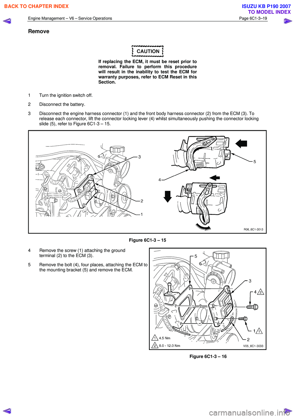
3 Disconnect the engine harness connector (1) and the front body harness connector (2) from the ECM (3). To release each connector, lift the connector locking lever (4) whilst simultaneously pushing the connector locking
slide (5), refer to Figure 6C1-3 – 15.
Figure 6C1-3 – 15
4 Remove the screw (1) attaching the ground terminal (2) to the ECM (3).
5 Remove the bolt (4), four places, attaching the ECM to the mounting bracket (5) and remove the ECM.
Figure 6C1-3 – 16
BACK TO CHAPTER INDEX
TO MODEL INDEX
ISUZU KB P190 2007
Page 3552 of 6020
Engine Management – V6 – Service Operations Page 6C1-3–28
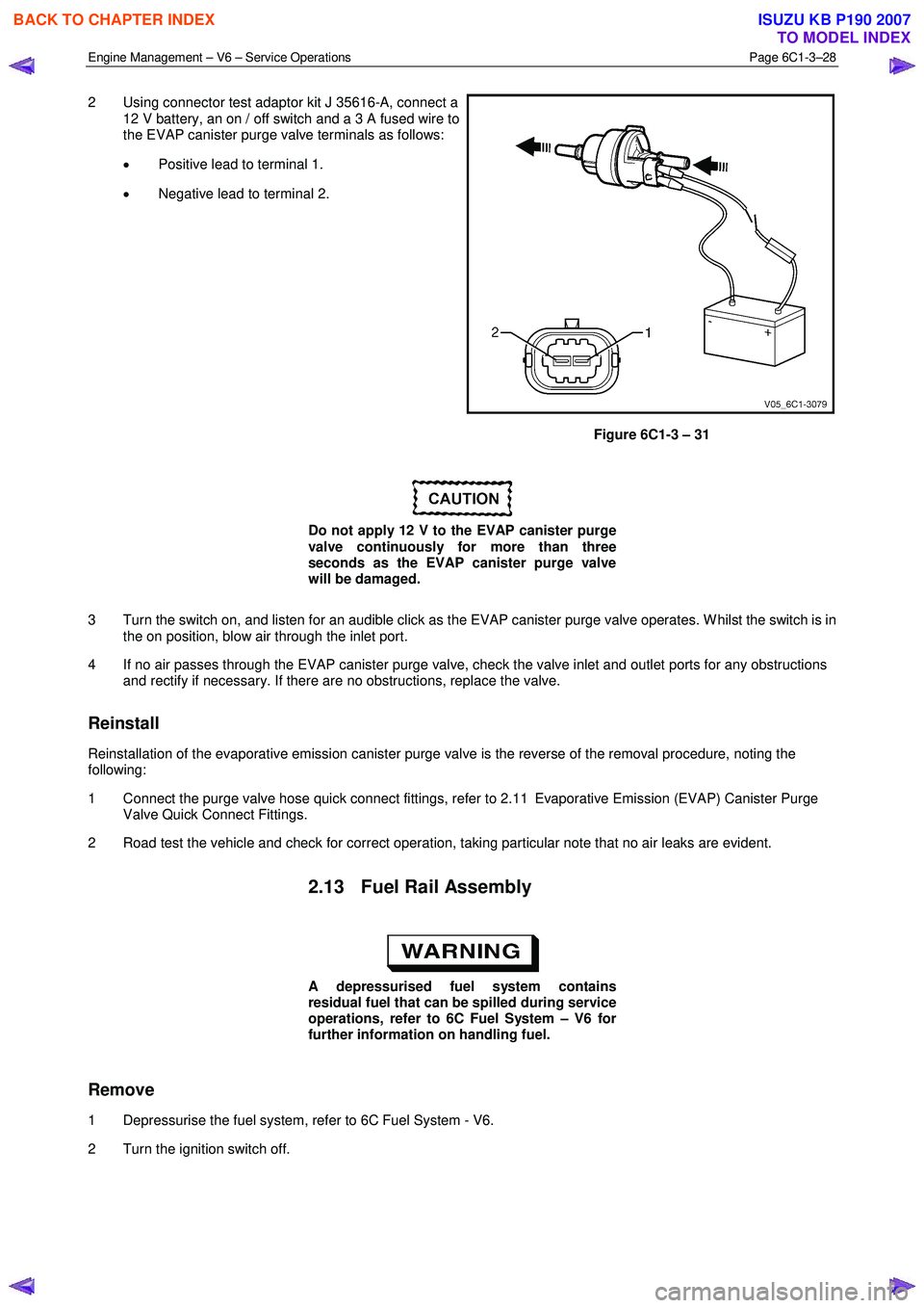
2 Using connector test adaptor kit J 35616-A, connect a
12 V battery, an on / off switch and a 3 A fused wire to
the EVAP canister purge valve terminals as follows:
• Positive lead to terminal 1.
• Negative lead to terminal 2.
Figure 6C1-3 – 31
Do not apply 12 V to the EVAP canister purge
valve continuously for more than three
seconds as the EVAP canister purge valve
will be damaged.
3 Turn the switch on, and listen for an audible click as the EVAP canister purge valve operates. W hilst the switch is in the on position, blow air through the inlet port.
4 If no air passes through the EVAP canister purge valve, check the valve inlet and outlet ports for any obstructions and rectify if necessary. If there are no obstructions, replace the valve.
Reinstall
Reinstallation of the evaporative emission canister purge valve is the reverse of the removal procedure, noting the
following:
1 Connect the purge valve hose quick connect fittings, refer to 2.11 Evaporative Emission (EVAP) Canister Purge Valve Quick Connect Fittings.
2 Road test the vehicle and check for correct operation, taking particular note that no air leaks are evident.
2.13 Fuel Rail Assembly
A depressurised fuel system contains
residual fuel that can be spilled during service
operations, refer to 6C Fuel System – V6 for
further information on handling fuel.
Remove
1 Depressurise the fuel system, refer to 6C Fuel System - V6.
2 Turn the ignition switch off.
BACK TO CHAPTER INDEX
TO MODEL INDEX
ISUZU KB P190 2007